SPYDER MODEL 7 VAV CONTROLLER INSTALLATION INSTRUCTIONS
31-00475-01
18
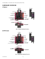
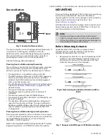
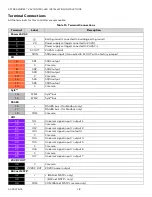
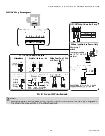
Terminal Connections
All the terminals for this controller are removable.
Table 15 Terminal Connections
Terminal
Label
Description
Power 24 VAC
1
Earth ground (connected to building earth ground)
2
V0
Power supply voltage (connected to 24 V0)
3
~
Power supply voltage (connected to 24 VAC~)
4
AC OUT
24 VAC~ output
5
SRIN
SSR power input ((connected to AC OUT with a factory jumper)
DO
6
SR1
SSR1 output
7
C
Common
8
SR2
SSR2 output
9
SR3
SSR3 output
10
C
Common
11
SR4
SSR4 output
12
SR5
SSR5 output
13
C
Common
Sylk ™
14
WM1
Sylk™ bus
15
WM2
Sylk™ bus
RS485
16
+
RS-485 bus + (for Modbus only)
17
-
RS-485 bus - (for Modbus only)
18
COM
Common
UIO
19
IO1
Universal signal input / output 1
20
C
Common
21
IO2
Universal signal input / output 2
22
IO3
Universal signal input/output 3
23
C
Common
24
IO4
Universal signal input / output 4
25
IO5
Universal signal input / output 5
26
C
Common
27
IO6
Universal signal input / output 6
28
C
Common
29
IO7
Universal signal input / output 7
20 VDC OUT
30
C
Common
31
20 VDC OUT
20 VDC power output
BACnet MSTP
32
+
+ (BACnet MSTP + only)
33
-
- (BACnet MSTP - only)
34
COM
COM (BACnet MSTP common only)

