


SmartPAC 2 with WPC Integration
1126800
SmartPAC 2 Keyboard, Displays
Chapter 3
Page 195
and Operating Modes
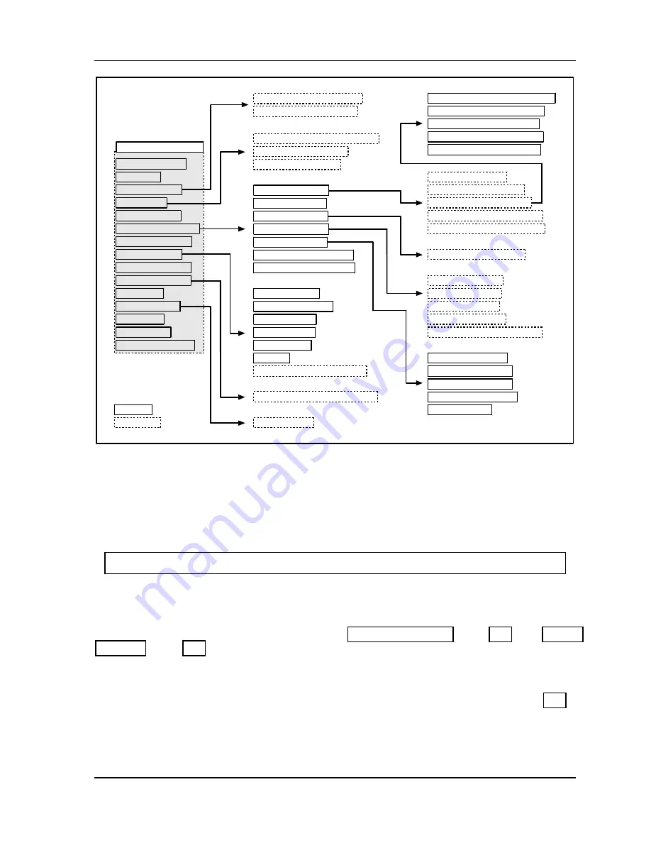
RUN MODE MAIN MENU
BRAKE MONITOR
ENABLE SENSORS
COUNTERS
DIE PROTECTION
CAM SWITCH
TONNAGE/WAVEFORM
PROCESS MONITOR
PRESS CONTROL
TOOL INFORMATION
SHUTGHT/CNTRBAL
ERROR LOG
LOAD NEW TOOL
MESSAGING
DIALOG MENU
TOGGLE HOT KEYS 1
F6
- VIEW SENSOR SUMMARY
F7
- SHOW SENSOR STATUS
F5
- VIEW GLOBAL CAM SUMMARY
F6
- VIEW CAM SUMMARY
F7
- SHOW CAM TIMING
SHOW WAVEFORMS
SHOW “PLAN” VIEW
SHOW BARGRAPHS
ADJUST SETPOINTS
TONNAGE HISTORY
RECALCULATE SETPOINTS
SHOW REVERSE TONNAGE
CURRENT TO STORED WAVEFORM
CURRENT TO HELD WAVEFORM
HELD TO STORED WAVEFORM
CURRENT TO CRITICAL CURVE
SET THE PRESS STROKES/MIN
F2
- HIGH SETPOINT
F3
- LOW SETPOINT
F4
- REP SETPOINT
F5
- SAMPLE PERIOD
F6
- RECALCULATE SETPOINTS
INPUT 1 = LEFT REAR
INPUT 2 = RIGHT REAR
INPUT 3 = LEFT FRONT
INPUT 4 = RIGHT FRONT
TOTAL TONNAGE
F6
- RESCALE THE GRAPH
F7
- SAVE CURRENT SHUT HEIGHT
F5
- LOAD TOOL
menu item
Function Key
F3
- UPDATE WAVEFORMS
F4
- COMPARE WAVEFORMS
F5
- STORE/HOLD WAVEFORMS
F1
- DISPLAY SELECT
F7
- SELECT OR ADD A WINDOW
TOP STOP ANGLE
CONTINUOUS SPEED
SINGLE STROKE
INCHING SPEED
COUNTER BAL.
MAIN AIR
F3
- SHOW OVERRUN ANGLES
Figure 3 - 23. Navigation Example: Run Mode
Press ENTER to go in direction of arrow. Press RESET to return to previous menu.
This illustration includes some optional features; your menus may be different.
Using Cursor Keys to Set Timing
For HELP press the HELP key located at the center of the cursor (arrow) keys.
Follow the instructions in this section to use the cursor keys to set timing for your optional
programmable cam switch and/or sensors. You can set the crankshaft angles at which you
want a cam channel or ready signal to turn ON and OFF. For detailed instructions on using
die protection sensors and cams, see Chapter 5, “DIE PROTECTION,” page 292, and “CAM
SWITCH,” page 302.
Usually you use one ON/OFF cycle for each cam. However, SmartPAC 2 enables you to set
additional ON/OFF cycles for cams. You can set up to four ON/OFF cycles on one cam,
with a maximum of six extra ON/OFF cycles distributed among all the cams. See page 307
for more information on setting multiple ON/OFF cycles.
When you are ready to set timing, there will be a crank angle clock diagram on your screen
(see the next illustration). The
crank angle clock
illustrates the ON and OFF angle settings
Содержание SmartPAC 2
Страница 192: ...1126800 SmartPAC 2 with WPC Integration Page 170 Chapter 2 Installing SmartPAC 2 and WPC ...
Страница 222: ...1126800 SmartPAC 2 with WPC Integration Page 200 Chapter 3 SmartPAC 2 Keyboard Displays and Operating Modes ...
Страница 294: ...1126800 SmartPAC 2 with WPC Integration Page 272 Chapter 4 SmartPAC 2 Initialization Mode ...
Страница 342: ...1126800 SmartPAC 2 with WPC Integration page 320 Chapter 5 SmartPAC 2 Program Mode ...
Страница 404: ...1126800 SmartPAC 2 with WPC Integration Page 382 Chapter 6 SmartPAC 2 Run Mode ...
Страница 448: ...1126800 SmartPAC 2 with WPC Integration Page 426 Chapter 7 SmartPAC 2 Fault Messages ...
Страница 476: ...1126800 SmartPAC 2 with WPC Integration page 454 Appendix C Updating SmartPAC 2 Firmware ...
Страница 478: ...1126800 SmartPAC 2 with WPC Integration page 456 Appendix D SmartView Remote Viewing and E mail Setup ...
Страница 480: ...1126800 SmartPAC 2 with WPC Integration page 458 Appendix E Upgrade from Original SmartPAC to SmartPAC 2 ...
Страница 482: ...1126800 SmartPAC 2 with WPC Integration page 460 Appendix F Replacing SmartPAC 2 PC Board ...
Страница 492: ...1126800 SmartPAC 2 with WPC Integration page 470 Glossary ...