SWIFT® Smart Wireless Integrated Fire Technology Manual —
P/N LS10036-000SK-E:G 4/13/2020
15
Configuration and Programming
WSK-WGI Wireless System Gateway
The gateway provides isolation of short circuits of the SLC in Class A (Style 6) installations. SLC connections are power-limited by the
panel. +24VDC must be power-limited by the source.
2.8 Configuration and Programming
To successfully configure and/or program the gateway:
1.
Create a profile. A profile binds a gateway and the devices in a mesh network together. The profile will contain a mesh ID that is
used when forming the associations. All devices, including the gateway, require a common profile.
2.
Assign a profile using SWIFT Tools. Assign the profile to every device that will be a part of the mesh. This will enable all the
devices that have that profile to form associative links when the mesh is formed.
3.
Form the mesh. The mesh cannot be formed until the profile is assigned to the gateway and to its devices.
Perform the follow steps using SWIFT Tools.
2.8.1 Assign a Profile
To assign a profile to the gateway using SWIFT Tools:
1.
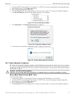
Connect the W-USB device to your laptop. For more information on the W-USB adapter, refer to Section 5, “W-USB Adapter”, on
page 40.
2.
Launch SWIFT Tools. Refer to Appendix A for more information.
3.
From the Home Screen, select the
Create Mesh Network
function.
4.
Create
a new profile or
Import
an existing profile as required.
5.
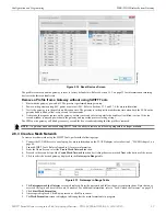
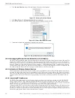
Select and open the profile to be assigned to the gateway from the Name drop-down box in the Profile section.
6.
Power on the gateway within approximately 20 feet of the laptop running SWIFT Tools.
7.
Place the devices with batteries installed within 20 feet of the laptop, with a minimum of 3 feet between each device. If the devices
were inadvertently installed in the building prior to assigning them profiles, either remove them to bring them near the laptop or
bring the laptop near each of the installed devices in order to assign them the profile.
+
+
-
-
+
-
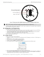
Figure 2.7 Wiring Connections: WSK-WGI Powered by an External, Reg24VDC Source
SLC in from FACP/device
Ex24VDC Power
SLC out to next device (Class B)
or SLC return to FACP (Class A)
2.
6.w
m
f
NOTE:
It is recommended to use the same wire gauge if there are multiple connections to the same terminal.
Figure 2.8 Selecting a Profile
assig
npro
fil
e
_
se
le
ct.jp
g


