background image

97

MAN0530 Issue 10 - 11/09 

Searchline Excel

2104M0506

Show Config

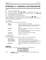
This option displays the configuration parameters the user can set in the same way as for the


Show Gas 

option. The configurable settings a

nd values are shown in the following table:

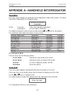
Configuration Parameters

  Display Text 

Min Value  Max Value  Step Size 

Default Values

Protocol Address


Digital


Address


255 

0

Time to Block


Block


Warn


Time


5s 

600s 

5s 

30

Time to Fault


Block


Fault


Time


0s 

600s 

5s 

120

Max Response


Maximum


T90


1s 

60s 

1s 

60

Analogue Style


Analogue


Mode


         Alarm or Continuous  

C

Inhibit Current


Inhibit


mA


0mA 

3mA 

0.05mA 

2.0

Block Current


Blocked


mA


0mA 

4mA 

0.05mA 

2.5

Low Signal Current 

Low


Signal


mA


0mA 

4mA 

0.05mA 

3.0

Low Signal Level 

Low


Signal


%


0% 

90% 

1% 

33%

Alarm Threshold


Alarm


Threshold


10% 

100% 

1% 

20%

Report fault due to blockage  

RPRT


Blocked


Fault

              Enable or Disable  

E


show install

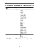
This  option  displays  the  installation  configuration  parameters  in  the  same  way  as  for  the


Show Gas 

option. The configurable settings and values are shown below:

Installation Configuration 

Display Text   

Description 


Parameters

System Type


System


Type


Short Range 


Medium Range 


Long Range 


Duct Mount

Path Length


Path


Length


5m min.  

200m max. 

1m step 


0.5m min. 

5m max. 

0.1m step

A.5.6  Chg Mode

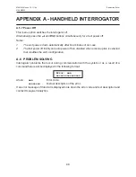
This menu option toggles the operating mode of the interrogator between 

Excel

Optima 

and 

Optima Plus

 to match the gas detector it is attached to. When invoked the mode is displayed 

in the identification banner (the same as the one displayed when the unit is switched on) for 

three seconds as follows:


   Z - SHC1 aaaaaa 


  Interrogator 4V0 

where: 

aaaaaa 

The type of gas detector that the interrogator is currently set to, i.e. 

Excel

,


OPTIMA 

or 

OPTIMA PLUS

.

APPENDIX A - HANDHELD INTERROGATOR

Содержание Searchline Excel

Страница 1: ...Searchline Excel Infrared Gas Detectors Technical Handbook ...

Страница 2: ...ectrical interference For electrical installation design considerations refer to Section 3 6 Operators must be fully aware of the action to be taken if the gas concentration exceeds an alarm level 7 Dismantling or repair of equipment should be carried out in the safe area only 8 Test gases may be toxic and or combustible Refer to Material Safety Sheets for appropriate warnings 9 Do not drill holes...

Страница 3: ...er should contact Honeywell Analytics Limited for advice 3 Effect of explosive atmosphere on materials Searchline Excel is made from materials which exhibit good resistance to corrosive and solvative substances The Exd enclosures are made from 316 stainless steel and the explosion protected windows are made from toughened soda lime glass Honeywell Analytics are not aware of any significant effects...

Страница 4: ... 24 3 6 Installation procedure 27 3 7 Alignment and commissioning 33 3 8 System Controller calibration 48 3 9 Installation Checks Tests 49 4 MAINTENANCE 55 4 1 Inspection and Cleaning 55 4 2 Functional Testing Plastic Test Filters 55 4 3 Calibration Check using the Gassing Cell 57 4 4 Display Gas Reading 58 4 5 Alignment Telescope 59 4 6 Operational Maintenance FM 59 5 Problem Solving 61 6 SPECIFI...

Страница 5: ...roduction 81 A 2 Overview 81 A 3 Connection to System 82 A 4 Basic User Tasks 83 A 5 Menus 84 A 6 Problem Solving 98 A 7 specification 99 APPENDIX B GLOSSARY 101 B 1 Terminology 101 B 2 Measurement Units 101 B 3 Abbreviations 102 APPENDIX C ACCESSORIES SPARE PARTS 103 C 1 System Units 103 C 2 General 104 ...

Страница 6: ...visible and Eye safe Searchline Excel is designed for use in the most demanding environments applications and provides a sensitive fast and reliable response The sophisticated open path technology provides immunity to sunlight and minimises the effects of environmental factors such as rain fog ice snow and condensation The Transmitter and Receiver units incorporate heated optics designed to minimi...

Страница 7: ...practice that could result in severe injury or death to personnel Caution Indicates hazardous or unsafe practice which could result in minor injury to personnel or product or property damage Note Provides useful helpful additional information If more information beyond the scope of this technical handbook is required please contact Honeywell Analytics Associated Documents Searchline Excel Open Pat...

Страница 8: ...d a Receiver This separate Transmitter Receiver configuration provides the most reliable basis for open path gas detection 2 OVERVIEW DVC100 M MK2 or DX100 M or other junction box Mounting plate Mounting bracket Pivot block Receiver Flexible conduit Monitored path 5 200 m Honeywell Analytics Junction Box 00780 A 0100 or other junction box Transmitter ...

Страница 9: ...itter produces an intense collimated infrared beam which is produced by a Xenon arc flashlamp The flashlamp s infrared output is collimated using mirrors which enables a more uniform beam no chromatic aberrations to be produced and hence reduces alignment sensitivity In order to prevent annoying visible flashes the visible emissions from the flashlamp are blocked by a filter The Transmitter s flas...

Страница 10: ...ments to enable hydrocarbon gases in the beam path to be detected Infrared radiation is collected by a single silicon lens which is common to both the sample and reference measurement channels This radiation is divided by a beamsplitter and fed to two filtered detectors sample and reference The sample detector input is filtered at wavelengths where strong infrared absorption is exhibited by the ta...

Страница 11: ...ing and output state The primary output of the Receiver is a signal in the range 4 20mA and is available as either source or sink options For most applications the output is calibrated for a range of 0 to 5 LEL m See Appendix B for the explanation of LEL m and other terms The Receiver also features an RS485 output which is used to communicate with the associated SHC1 Handheld Interrogator The SHC1...

Страница 12: ...e Made from stainless steel Fully adjustable for alignment Coarse and fine settings in both horizontal and vertical planes Adjustment range Vertical 45o Horizontal 90o Alignment details are given in Chapter 3 2 OVERVIEW Clamp nut Mounting bracket adjusting screw 2 off Adjustment clamp lock screw 2 off Clamp nut Pivot block adjusting screw Adjustment clamp lock screw 2 off ...

Страница 13: ...nstallation design authority reads all of this chapter and considers how the information and recommendations provided can be applied to their installation s If you have any queries concerning your installation design contact Honeywell Analytics or your local agents Honeywell Analytics is committed to ensuring that customers achieve reliable operation of their Searchline Excel Gas Detectors For thi...

Страница 14: ...ntribute significantly to the overall reliability and availability When locating units attempt to avoid areas where they may be adversely affected by the following Vibration Angular vibration of the structure to which Excel units are attached should be kept to less than 0 5 Where possible avoid locations where high levels of vibration will be directly induced into the mounting structure If close p...

Страница 15: ...s a chance that during or after an earthquake the units of an Excel gas detector will become misaligned with respect to each other Provided that the Excel units do not suffer from direct mechanical impact damage during an earthquake they should remain undamaged by such events Anti vibration mounts are unlikely to be of any benefit and are not recommended After an earthquake it is recommended that ...

Страница 16: ...l areas d Splash and spray e g from moving equipment cooling towers etc e Parking loading cranes vehicle temporary stops e g bus stops road junctions etc f Vegetation e g shrubs bushes branches etc if currently clear movement due to weather and future growth or planting must be considered Note Where c and d cannot be avoided consider indicating the beam by marking the walkway or road with paint No...

Страница 17: ... 3m the supporting structure shown is recommended Note The pipe can be filled with concrete to provide extra robustness if necessary 3 2 5 Orientation Searchline Excel is solar immune and therefore there is no need to take account of the sun s movement when considering orientation When positioning the units do not install them with the optical axis at an angle greater than 45o to the horizontal Th...

Страница 18: ... the low noise instrument earth Star earthing arrangements minimise earth current crosstalk d The shields of the field cabling should not be connected such that earth loops are produced or in a manner that will result in the shields carrying large currents from heavy plant or equipment e Ideally the field cable shield should be connected to the unit s green yellow GND wire providing a single conti...

Страница 19: ...ficient cross sectional area to ensure that the minimum supply voltage applied to the gas detector is 18V at a current of 420mA This corresponds to a maximum round loop impedance of 14 ohms for a nominal 24V system supply n Receivers should not be installed in close proximity to the antennae of high powered radio radar and satellite communication equipment The following diagrams show typical earth...

Страница 20: ... B TB1 5 Modbus Drain CABLE SCREEN SAFETY PROTECTIVE GROUND Where the DX100 M is not bonded to a local safety protective earth then an external safety protective earth needs to be made as shown GREEN YELLOW EARTH Same potential as Excel body and conduit WHITE 4 20mA TB2 3 CONTROL CABINET CONNECTIONS CABLE SCREEN CABLE SCREEN INSTRUMENT CLEAN EARTH STAR POINT Modbus B TB1 5 Modbus A TB1 6 Modbus Dr...

Страница 21: ...4 20mA TB2 3 BLACK 0V TB2 5 CABLE SCREEN CABLE SCREEN RS485 B Blue Terminal 8 RS485 A Orange Terminal 7 4 20mA White Terminal 6 0V Black Terminal 4 24VDC Red Terminal 2 Earth Terminal 3 INSTALLATION AND OPERATION 3 3 5 Remote Installations For remote or difficult to access installations the DVC100 M MK2 or DX100 M can be positioned in a convenient location by using an intervening junction box e g ...

Страница 22: ...NCTION BOX mounted in a convenient and accessible position CABLE SCREEN GREEN YELLOW EARTH BLUE B TB1 3 RED 24V TB2 1 BLACK 0V TB2 5 WHITE 4 20mA TB2 3 SAFETY PROTECTIVE GROUND Where the DX 100 M is not bonded to a local safety protective earth then an external safety protective earth needs to be made as shown CABLE SCREEN CONTROL CABINET CONNECTIONS 4 20mA OUT TB2 3 0V TB2 6 24V TB2 2 CABLE SCREE...

Страница 23: ...disabled Notes 1 Control room supply voltage assumed to be 24V 2 Standard configuration of the Transmitter is with turbo heating enabled Terminal sizes DVC100 M MK2 0 5mm2 4mm2 20AWG 12AWG DX100 M 0 5mm2 4mm2 20AWG 12AWG Honeywell Analytics Junction Box 00780 A 0100 0 5mm2 6mm2 20AWG 10AWG 3 4 2 Power Supply Connections Turbo heating Disabled When connected as shown in section 3 3 4 Transmitter Co...

Страница 24: ...of the following items Where alternative component sizes are given the size depends on the version of unit i e mid long range version or short range version 1 x Receiver Unit 1 x Transmitter Unit 3 INSTALLATION AND OPERATION The earth bonding arrangement must ensure that the maximum peak voltage between the unit case earth and any field cable conductor is less than 350V Voltages in excess of this ...

Страница 25: ...unting Brackets with grub screws 2 x Pivot Blocks 4 x Adjustment Clamps with grub screws with grub screws 4 x Nuts 4 x Washers M12 or M20 6 x Mounting Bracket 8 x Junction box Mounting Bolts Fixing Bolts M10 or M12 2 x Isolation Kits 4 x Spring Washers 3 Installation and Operation ...

Страница 26: ... 1 UN IT DI ME NS IO NS W idt h 5 5 1 in 1 40 mm He igh t 5 90 in 1 50 mm De pth 5 98 in 1 52 mm He igh t wi th se ns or 10 63 in 2 70 mm 11 13 in 2 82 mm wi th O se ns or fitt ed 5 5 1 in 1 40 mm He igh t 5 90 in 1 50 mm De pth 5 98 in 1 52 mm He igh t wi th se ns or 10 63 in 2 70 mm 11 13 in 2 82 mm wi th O se ns or fitt 2 2 3 1 UN IT DI ME NS IO NS W idt h 5 5 1 in 1 40 mm He igh t 5 90 in 1 50...

Страница 27: ... the Receiver and the Transmitter 1 Ensure that the gas detector equipment supplied is compatible with the required application i e short medium or long range 2 Fit the mounting bracket and isolation kit to the mounting plate for the unit as shown 3 Fit the mounting plate to the supporting structure The plate can be fitted in one of the following ways a With bolts directly to a flat surface b With...

Страница 28: ...entity Quantity Size Used For A 8 7 5mm Dual 2 pipe or pole mounting flat surface mounting B 8 9 5mm Single 6 pole flat surface mounting Dual 2 5 ID pipe C 4 M6 tapped 00780 A 0100 junction box mounting 3 Installation and Operation Always mount plate this way up 60x45 2 POSNS 6mm thick stainless steel plate A D1 D D1 D E C C F F D G G G G C C E E E J J J H H H A B B B B B B B B A A A A A A 224 15 ...

Страница 29: ...illark Akron junction box mounting G 4 M6 tapped Sun heat shade mounting H 3 M8 tapped Short range Transmitter and all Receiver brackets J 3 M10 tapped Medium Long range Transmitter mounting bracket The following drawings show typical mountings Mounting Plate Fixed to Flat Surface Mounting Plate Fixed to Single Pipe Pole 3 Installation and Operation M8 mounting bolt 4 off not supplied using B hole...

Страница 30: ... the adjustment clamp s grubscrews until they just grip the unthreaded part of the stud 6 Fit the pivot block to the mounting bracket using a clamp nut and washer M12 or M20 The correct orientation for the pivot blocks and mounting brackets is as follows Do not fully tighten the nut Refer to 3 73 3 Installation and Operation Clamp nut and washer 2 5in U bolt 4 off not supplied using A holes Mounti...

Страница 31: ...of the unit s mounting stud 9 Fit the unit to the pivot block using a clamp nut and washer M12 or M20 Do not fully tighten the nut Refer to 3 73 At this point position the units on their mountings so that their optical windows face each other as shown Ensure that the adjustment clamp s stub lever is approximately centrally positioned between the pivot block s grub screws Adjust the screws if requi...

Страница 32: ...he units are to be installed with junction boxes other than DVC DX100 M types ensure that the boxes have a M20 cable gland entries for ATEX IECEx units or 3 4 NPT for UL and CSA b terminals for five wires and an earth 2 Remove the M20 blanking plugs if fitted and attach the Searchline Excel Transmitter and Receiver cables to their junction box Fit the locking rings if supplied before terminating t...

Страница 33: ...ated The Handheld Interrogator is then attached to the Receiver to finally commission the equipment and depending on the type of Receiver may need to be used to assist in fine tuning the alignment The procedure can be performed by a single technician Each gas detector unit features a mounting assembly that allow both coarse and fine mechanical adjustment in the horizontal and vertical directions a...

Страница 34: ...ional SHC Protection Device see Appendix C Accessories Spare Parts see Note 8 Appropriate plastic test filters see Chapter 5 section 5 1 2 3mm hex Allen key 19mm spanner with additional 24mm spanner for mid long range gas detectors Notes 1 Ideally carry out the alignment procedure on a clear day 2 Get familiar with the workings of the adjustable parts of the gas detector before proceeding with the...

Страница 35: ...ews should need to be tightened Further tightening later on will affect the fine adjustment and should be avoided Note The unit can still be moved by the adjustment screws 3 7 4 Accurate Alignment The procedure for accurately aligning the Transmitter and Receiver units is the same Before making any adjustments consult the following table to ensure that the correct type of telescope is used with th...

Страница 36: ...y attached to a datum mount that features a latching mechanism It can be used with either the Trident or non Trident types of Excel units When used with the non Trident Excel the alignment may also need to be fine tuned and then verified using the SHC1 Handheld Interrogator The latches are used to lock the whole assembly onto the body of the Excel unit Before securing the latches the telescope can...

Страница 37: ...ure the latches as indicated by arrow 3 A horizontal viewing position is the easiest to interpret Now align the units by continuing with step 5 Note Take care when undoing the latches to remove the alignment telescope not to touch the springs 3 Installation and Operation Excel unit Cowl Telescope viewfinder Alignment telescope Datum mount Mirror assembly Mounting latch assembly Latch 2 off ...

Страница 38: ...e datum mount the telescope can be rotated to a convenient viewing position To remove the telescope assembly reverse the following mounting procedure a Align the telescope s two datum mount bayonet slots with the two locating pins on the cowl of the unit as shown b Push the telescope datum mount fully home onto the two pins on the cowl c Without disturbing the datum mount use one hand to rotate th...

Страница 39: ...sion springs After attaching the telescope assembly align the units by continuing with step 5 5 Align the Excel unit using the two sets of assembly adjustment screws so that the cross hairs viewed through the alignment telescope are centred on the window of the other Excel unit View the image with the eye placed approximately 3 inches from the viewfinder 3 Installation and Operation Approximately ...

Страница 40: ...n correctly adjusted tighten both adjustment screws simultaneously Ensure there is minimum movement whilst locking the assembly 8 Check alignment and repeat steps 5 to 7 as necessary 9 Remove the telescope assembly from the unit by reversing the fitting instructions 10 Carry out the final commissioning procedures described in the next sub section 3 Installation and Operation Off axis view Clamp nu...

Страница 41: ...n with the installed Excel gas detector Set the gas detector real time clock Complete the alignment process Finish up Connecting the Interrogator Connect the SHC1 Handheld Interrogator to the gas detector in one of the following ways via a HoneywellAnalytics DVC100 M MK2 or DX100 M Junction Box connect the Interrogator directly to the junction box via its IS socket e g ESC Calibrator Type SHC1 3 I...

Страница 42: ...ng the protection device 1 Isolate all power supplies 2 Remove the cover of the junction box 3 Hard wire the flying lead of the SHC Protection Device to the communications link terminals in the box as shown 4 Connect the Interrogator to the IS connector on the end of the SHC Protection Device Powering Up 1 Apply power to the Excel Transmitter and Receiver units 2 Press and hold the Enter key on th...

Страница 43: ...he Interrogator mode between Excel Optima Plus and Optima The start up message is updated and displayed again for 3 seconds then the unit displays the Main menu which is the top level of its Interrogator s menu style interface as follows Main Display The first line of the display shows the current level in the menu tree and the second line displays a sub menu title action or data Setting the Real ...

Страница 44: ...d and the new month setting is then displayed 11 Repeat the procedure to set the month and year 12 When complete press Enter on the keypad to return to the Calibrate menu Notes 1 The time and date will not be updated unless both are entered and accepted without error 2 Pressing ESC on the keypad at any time aborts the current setting immediately and returns to the previous setting or menu option C...

Страница 45: ...inimum and maximum path length entry options for each gas detector are System Type Minimum Range m Maximum Range m Step Size m Short Range 5 40 1 Medium Range 20 120 1 Long Range 120 200 1 Duct Mount 0 5 5 0 1 9 When finished press Enter on the keypad A self test routine is started and the display shows the following message Self Test Please Wait When the test is successfully finished the followin...

Страница 46: ...s on the type of alignment telescope and mounting initially used to set up the Excel gas detector Bayonet style Trident type telescope assembly If this type of alignment telescope was used with a Trident type Excel gas detector there is no need to further optimise the alignment using the SHC1 Handheld Interrogator When the SIG and TGT bar graphs are displayed on the SHC1 screen SIG will always be ...

Страница 47: ... alignment by placing a hex Allen key in the pair of grub screws which control adjustment in a particular plane and simultaneously rotating them in opposite directions h Repeat this for the other pair of grub screws i Press Enter and the signal levels are checked With the SIG level is greater than the TGT level the signal check should pass and the screen should display the following message Signal...

Страница 48: ...own automatically after five minutes of non use 2 Fast power off and auto power off are disabled when any menu option is selected that modifies the unit s configuration 3 Disconnect the Interrogator from the gas detector reversing the process described at the beginning of section 3 7 5 3 8 System Controller calibration This procedure is used to set up the system controller using the Searchline Exc...

Страница 49: ...leased The fixed output is released and the gas detector returns to normal operation 12 Turn off the Interrogator and disconnect it from the gas detector 3 9 Installation Checks Tests The following information is for the guidance of personnel carrying out installation checks tests on Searchline Excel In general it should be noted that Searchline Excel should only be installed by fully trained pers...

Страница 50: ...E RX MOD STATE TX CERTIFICATION CHECK TEST RECIEVER CHECK TEST TRANSMITTER Mount Rigidity Mount Rigidity Vibration Vibration Excess Heat Excess Heat Supply Voltage Supply Voltage Earthing Earthing RFI EMC RFI EMC Contaminants Contaminants BEAM OBSTRUCTIONS BLOCKS cont TEST FILTER Response Pass Fail 4 20mA LOOP INTEGRITY Pass Fail Untested FAULT WARNING LOG Clear Faults Warnings cont INSTALLATION S...

Страница 51: ...cation of the units e g ATEX UL CSA FM IECEx Mount Rigidity Check that the units have been mounted securely to the supporting structure Check that the supporting structure is sufficiently rigid to maintain alignment in the anticipated operating conditions A maximum angular movement of 0 5o is allowable As an approximate guideline a sufficiently rigid mount supporting structure will only move a few...

Страница 52: ...nit has been isolated from local metalwork earths and is connected to a clean instrument earth enter Instrument earth See section 3 3 Electrical Connections RFI EMC Assess the installation cabling and its close surrounds for known potential sources of excessive RF Electromagnetic Interference Such sources could include radio radar transmission antennae high voltage switch gear large electrical gen...

Страница 53: ... etc If there is a realistic possibility that they could cause a significant problem enter a brief description e g Personnel in corridor Loading bay vehicles Test Filter After completing the installation procedure enter the DISPLAY mode and test the gas detector response with a plastic test filter Enter the nominal value of the test filter the unit s displayed response and mark the Pass or Fail bo...

Страница 54: ...laring an installation unsatisfactory could include excessive movement vibration of unit s mounting received signal levels too low supply voltage too low 4 20mA loop integrity faults unclearable active faults any prevailing or probable condition which is known to unacceptably reduce reliability or availability If Installation is Unsatisfactory Reasons Briefly state the principal reasons why the in...

Страница 55: ...lect DISPLAY from the Calibration menu 3 Clean any dust or dirt from the Searchline Excel windows using soapy water and a soft cloth 4 Using the SHC1 Handheld Interrogator release the Searchline Excel signal output The output can be released by pressing ESC followed by on the keyboard 5 Using the SHC1 Handheld Interrogator re zero the unit See Appendix A for details about how to use the Interrogat...

Страница 56: ...1 4 LEL m E 1 5 2 8 LEL m 6 If this is the first time that the unit has been tested with this particular test filter record the gas reading that is produced This reading should be used to verify correct operation in the future 7 If this is not the first time that the unit has been tested with this particular filter note the gas reading it produces and compare it to the original value recorded for ...

Страница 57: ...me as the test gas used during the factory calibration of the Searchline Excel unit and ideally the concentration should be between 2 and 5 LEL m and never below 1 LEL m Note Where a different test gas is used the typical value for cross sensitivity is not sufficiently precise to enable valid calibration checks to be performed using the Gassing Cell however response tests can be easily performed w...

Страница 58: ...output is as indicated in the above table 5 fsd 5 Remove the gassing cell 6 Re zero Searchline Excel Note Pentane cannot be used with the gassing cell At normal temperatures these substances do not vapourise sufficiently to give a useful signal in the short path of the gassing cell 4 4 Display Gas Reading This procedure displays details about the current gas gas table Carry out the following proce...

Страница 59: ...it from the gas detector 4 5 Alignment Telescope To clean the telescope lens mirror 1 Moisten the surface of the lens mirror by breathing on it 2 Using a soft tissue or lens cloth lightly wipe the lens mirror dry with a minimum number of strokes The wiping material may be slightly dampened with a lens cleaning fluid as sold in any camera store 4 6 Operational Maintenance FM As required as a criter...

Страница 60: ... beam path Record the response to the test filter and verify that the response is within the tolerance for stability and repeatability Following the procedure described in section 5 1 3 test the unit s response to high V V gas in a gassing cell Verify that the response is within the tolerance for stability and repeatability 4 MAINTENANCE ...

Страница 61: ...ssues refer to the DX100 Series Termination Units Technical Handbook If after following the recommendations in this section the problem persists please make available the following information before contacting Honeywell Analytics Installation Check Sheet See Chapter 3 Any error message Displayed on the Handheld Interrogator screen Any error code Displayed on the Handheld Interrogator screen Fault...

Страница 62: ...any obstruction if present Transmitter or Receiver 1 Connect SHC1 Interrogator to unit and check signal misaligned levels 2 Ifsignallevelsarelow usethetelescopeandSHC1 Interrogator to optimise Receiver alignment 3 If signal levels remain low after re aligning Receiver check the Transmitter alignment using the telescope 4 Re zero the unit after alignment See Appendix A 5 3 4 Output is 3mA Heavy con...

Страница 63: ...it correctly The Supply voltage at unit should be between 18V and 32V Interrogator battery low Check the Interrogator battery and replace if low See Appendix A Section A 4 3 Interrogator The installation has failed to 1 Check that the signal levels reaching the Installation meet the acceptable criteria Receiver are greater than 0 7 and less than 2 0 Failed message of the Instrument Assisted 2 Chec...

Страница 64: ...ic test filters See section 5 1 2 1 Check that the response to the test filters is within the limits stated in this handbook See section 5 1 2 2 Check that the value being used for response testing corresponds correctly to the target gas that the unit has been calibrated for Receiver misaligned 1 Use the telescope and Interrogator to optimise Receiver alignment 2 Re zero unit Contamination of wind...

Страница 65: ... along with its warranty Such equipment should be removed from service in potentially explosive atmospheres 2 Investigate the cause of the excessive temperature excursion and take steps to prevent recurrence e g fit sunshade or heat shield or relocate detector etc Diagnostics Incorrect supply voltage 1 Check that the 24V supply voltage is report reaching unit reaching the unit Supply Fault it shou...

Страница 66: ...to 65 C 40 F to 150 F Humidity All 0 99 RH Non condensing Pressure All 91 5kPa 105 5kPa 915 1055mBar non compensated Repeatability 0 4LELm 0 4LELm 0 4LELm Temperature 0 2LEL m zero 0 2LEL m zero 0 2LEL m zero 10 LEL LEL m zero Drift 40 C to 65 C 0 5LEL m 3LEL m 0 5LEL m 3LEL m 0 5LEL m 3LEL m 15 LEL LEL m 60 LEL Warm up Time All less than 5 minutes operational Less than 1 hour fully stabilised Pow...

Страница 67: ...drocarbon gases individually or in a mixture in the range 0 5 LEL m Methane CH4 Ethane C2 H6 Propane C3 H8 Butane C4 H10 Pentane C5 H12 Ethylene C2 H4 Propylene C3 H6 Butadiene C4 H6 Searchline Excel Raw Gas Response Before Linearity Correction Cross sensitivity to other gases Relative Response LEL m Methanol Ethane Propane Butane Methane Ethylene Hexane Ethanol Propylene Butadiene Pentane ...

Страница 68: ...2299X Open Path Short Range Transmitter and Receivers IECEx BAS 09 0100X Open Path Long Range Mid Range Transmitters IECEx BAS 09 0101X UL Class 1 Groups B C D Class 1 Zone 1 AEx d IIB Hydrogen Amb 40o C to 65o C File No E91044 CSA FM Class 1 Div 1 groups B C D T5 and Class I Div 1 groups B C D T5 Exd IIC T5 Amb 40 to 65o C Tamb 40 to 65o C File No LR 48148 38 The Searchline Excel system has been ...

Страница 69: ... Later units will be 1 2 NPT 7 2 2 Receiver Details Open Path 7 CERTIFICATION Receiver Ex d IIC T5 40 to 65 C Ex d IIC T6 40 to 40 C II 2G V max 32V 1 2 NPT gland Flexible Conduit 900mm long see table of Conduit Technical Characteristics M20 gland Ex e customer supply Certified M25 blank fitted M20 gland Ex e Ex d IECEx d IECEx d Certified Certified M20 blank fitted IS Cable Length 15m max DVC100 ...

Страница 70: ...an 24kV Insulation Resistance More than 100M ohms Connector Pull off Classification FRG04 Heavy Conductor Crush Classification FRG04 Heavy Flame Propagation Flame dies in less than 30 seconds after ignition source is removed Approvals Bureau Veritas 7 2 4 Certification Labels Product name and part number Unit type Explosion protection mark and equipment group and category Certified ambient tempera...

Страница 71: ...ATIONS FIXED SOCKET I S OUTPUT TO CALIBRATOR FACTORY FITTED HANDHELD CALIBRATOR TYPE SCH 1 Baseefa03ATEX0073 IECEx BAS 09 0120 NOTES 1 APPARATUS WHICH IS UNSPECIFIED EXCEPT THAT IT MUST NOT BE SUPPLIED FROM NOR CONTAIN IN NORMAL OR ABNORMAL CONDITIONS A SOURCE OF POTENTIAL WITH RESPECT TO EARTH IN EXCESS OF 250V rms OR 250V d c 2 INSTALL IN COMPLIANCE WITH IEC 60079 14 3 ENTRIES ANY SUITABLY APPRO...

Страница 72: ...72 MAN0530 Issue 10 11 09 Searchline Excel 2104M0506 7 CERTIFICATION 7 2 5 System Diagram ...

Страница 73: ... 65 C Conduit seal required see OEM J B details 7 3 2 Receivers Open Path UL approved M20 0 5in NPT adaptor Note Later units 1 2 NPT threaded without adaptor IS Cable Length 15m max Flexible conduit customer supplied must conform with the relevant US installation codes of practice see Control Drawing 2104E0045 Receiver Class I Div 1 Groups B C D Class I Zone 1 AEx d IIB H2 Tamb 40 to 65 C DX100 DX...

Страница 74: ...74 MAN0530 Issue 10 11 09 Searchline Excel 2104M0506 7 CERTIFICATION 7 3 3 System Diagram With DX100 Termination Unit ...

Страница 75: ...OR ABNORMAL CONDITIONS A SOURCE OF POTENTIAL WITH RESPECT TO EARTH IN EXCESS OF 250V rms OR 250V d c 2 WIRING FROM THE HANDHELD CALIBRATOR SHC1 TO THE TERMINATION UNIT DX100 IS NOT TO EXCEED 15 METRES MAX 3 INSTALL EQUIPMENT INCLUDING FIELD WIRING IN ACCORDANCE WITH ARTICLES OF THE NATIONAL ELECTRICAL CODE FOR DIVISION 1HAZARDOUS LOCATIONS SENSOR ENTRY CONDUIT CONNECTION REQUIRED WITH SEAL NON HAZ...

Страница 76: ...box CSA Receiver Class 1 Div 1 Groups B C D T5 Exd 11C T5 Tamb 40 to 65o C DX100 DX100 M CSA FM Termination Unit Class I Div 1 Groups B C D Tamb 40 to 65o C SHC1 Handheld Interrogator CSA FM Class 1 Div 1 Groups B C D Tamb 40 to 65o C FM Receiver Class 1 Div 1 Groups B C D 40 to 65o C CSA approved M20 0 5in NPT adaptor Note Later units 1 2 NPT threaded without adaptor Flexible conduit customer sup...

Страница 77: ...tomer supplied 7 CERTIFICATION CSA Receiver Class 1 Div 1 Groups B C D Class 1 Zone 1 AEx d IIB H2 Tamb 40 to 65o C DX100 DX100 M CSA FM Termination Unit Class I Div 1 Groups B C D Tamb 25 to 40o C SHC1 Handheld Interrogator CSA FM Class 1 Div 1 Groups B C D Tamb 50 to 40o C FM Receiver Class 1 Div 1 Groups B C D 40 to 65o C UL approved M20 0 5in NPT adaptor Note Later units 1 2 NPT threaded witho...

Страница 78: ...78 MAN0530 Issue 10 11 09 Searchline Excel 2104M0506 7 CERTIFICATION CSA FM Certification Label Standard Transmitter Standard Receiver Long Range Transmitter ...

Страница 79: ...79 MAN0530 Issue 10 11 09 Searchline Excel 2104M0506 7 CERTIFICATION ...

Страница 80: ...80 MAN0530 Issue 10 11 09 Searchline Excel 2104M0506 7 CERTIFICATION With DX100 M Termination Unit ...

Страница 81: ...r to the Excel systems basic user tasks including switching on off and changing the battery a detailed description of the menus which the interrogator provides problem solving information if trouble occurs when using the interrogator Details of how to use the interrogator for different tasks with the system are given Chapter 3 and Chapter 4 of this handbook A 2 Overview The interrogator consists o...

Страница 82: ...ad buttons are used to provide operator input in response to messages shown on the display This includes menu option selections and changing parameter values The four buttons are Up Move to the previous menu option list item or increase a displayed data value Down Move to the next menu option list item or decrease a displayed data value ESC Escape Quit the current menu level or operation and retur...

Страница 83: ... initial message is displayed This changes the mode and re displays the message Switching Off 1 Select the Power Off option from the Main Menu Alternatively press the and esc buttons simultaneously for a fast power off Notes 1 The unit powers down automatically after five minutes of non use 2 The fast power off facility and auto power off are disabled when a menu option is selected that modifies t...

Страница 84: ...sition Re use protective sleeve 5 Carefully replace the front half of the Interrogator back into the rear cover ensuring the flexible connector lies flat 6 Using a 2 5mm allen hexagonal key tighten the four screws on the rear cover of the Interrogator A 5 Menus The interrogator top level menu structure and menu choices are as follows All menu options are implemented by pressing the keypad key The ...

Страница 85: ...cientsorshowtheinstrument status Diagnose Inspect the fault and warning logs perform a self test or perform a soft reset Config Read the configuration parameters of the unit update the user configuration parameters Chg Mode Toggle the operating mode of the interrogator Power Off Switch the interrogator off A 5 2 Display Menu This sub menu displays gas and other unit readings It has the following o...

Страница 86: ...gnal magnitude for the reference channel Dynamic Reserve Shows the acceptable drop in signal level before beam block occurs as a percentage of the current signal level The display is in the following format Dynamic Reserve xxx xx where xxx xx The acceptable drop in signal level before beam block measured as a percentage of the current signal level S W Version Displays the system software version a...

Страница 87: ...ore the selected sub menu operation is started the following message is displayed for at least three seconds Inhibiting 4 20 Please Wait The analogue output is inhibited and the chosen sub menu operation proceeds After the sub menu operation is completed or aborted by pressing the ESC key the following message is displayed Press Enter To Release 4 20 Press to release the 4 20 receiver output and t...

Страница 88: ...one of the following Display Text System Type Short Range 40m range system Medium Range 120m range system Long Range 200m range system Duct Mount 0 5 5m range system Note It is not possible to change the system type This is set during calibration and configuration of the unit at the factory Path Length The following message is displayed Path Length nnnn where nnnn The path length in metres The fol...

Страница 89: ...ive of alignment is to maximise the SIG level Maximised SIG corresponds to optimal alignment 2 The Instrument Assisted Alignment IAA system only allows Excel to be initialised if the SIG level is greater than or equal to the TGT level when Enter is pressed 3 The smallest TGT signal level that is initially set will be equivalent to 70 0 700 of the signal expected for the installation s path length ...

Страница 90: ...ely 10 seconds During this time the TGT level will move up towards the current SIG level b Whilst watching the SIG level closely make a small mechanical adjustment in either the horizontal or vertical alignment and note whether the SIG level goes up or down c If the SIG level goes up make another small mechanical adjustment in the same direction as before d If the SIG level goes down change the di...

Страница 91: ...ion lets you set the system s time and date The initial display after SET Time is chosen is in the following format Time HH MM hh mm where hh Hours mm Minutes When first displayed only the current hour is shown All settings are adjusted by means of the and keys on the keypad After setting the hour the minutes are displayed After the time has been entered then the same process is used to set the da...

Страница 92: ...ee seconds Zero Calibrated Force mA This option allows the system s analogue output signal to be adjusted to a fixed level e g when setting up a system controller The following message is displayed O P current mA mmmmm where mmmmm Current to output This is adjusted using the and keys over the range 1mA to 21mA in steps of 0 1mA After adjustment the output is forced to the set level and the followi...

Страница 93: ...ation Analogue Output Uncalibrated Calibrated Det Temp Comp T Compensation Uncalibrated Calibrated Det Sens Comp Det Sensitivity Uncalibrated Calibrated Installation Installation Required Complete Valid Date Time Date and Time Estimated Set Loop Test Analogue Check Failed Passed A 5 4 Diagnose Menu This sub menu has the following options Active Faults Display the active faults in the system Active...

Страница 94: ...active warnings in the system They are displayed in the same way as described for Active Faults except that a W is displayed instead of F on the first line of the display Display Text Fault Description Meaning Alarm ERR_EXCEL_LOG_ALARM The Excel log has become damaged Bad Temperature ERR_EXCEL_TEMPERATURE_LIMIT Unit has been operated at a temperature outside its specified and certified range Basel...

Страница 95: ...played for three seconds when the process is completed Unit Reset A 5 5 Config Menu This sub menu lets you check the configuration parameters of the unit and update the user configuration parameters It has the following options Show Gas Show the gas related configuration parameters Show Config Show the user related configuration parameters Show Install Show the installation related configuration p...

Страница 96: ...tane UEGm 12 Hexane UEGm 20 Methane 21 Ethane 22 Propane 23 Butane 24 Pentane 25 Hexane 26 Ethylene 27 Propylene 28 Butadiene 29 Ethanol 30 Methanol 31 Methane UEGm 32 Ethane UEGm 33 Propane UEGm 34 Butane UEGm 35 Pentane UEGm 36 Hexane UEGm 37 Ethylene UEGm 38 Propylene UEGm 39 Butadiene UEGm 40 Ethanol UEGm 41 Methanol UEGm Gas Units Gas Units LELm PPMm UEGm or VVm LEL Cross Duct only Effective ...

Страница 97: ...reshold 10 100 1 20 Report fault due to blockage RPRT Blocked Fault Enable or Disable E Show Install This option displays the installation configuration parameters in the same way as for the Show Gas option The configurable settings and values are shown below Installation Configuration Display Text Description Parameters System Type System Type Short Range Medium Range Long Range Duct Mount Path L...

Страница 98: ...ower off are disabled when a menu option is selected that modifies the unit s configuration A 6 Problem Solving Interrogator problems that occur during communication with the system or as a result of a command failure will be displayed in the following format Error eee ssssssssssssssss where eee Error code ssssssss Textual description of the error If an error message of this kind is displayed note...

Страница 99: ...60079 0 2004 Ed 4 and IEC60079 11 Ed 5 ATEX Baseefa03ATEX0073 IECEx BAS 09 0120 II 2G Ex ia IIC T4 T4 amb 40 C to 40 C OPERATING TEMPERATURE RANGE 0 C to 40 C DMT evaluated 25 C to 55 C STORAGE TEMPERATURE RANGE 10 C to 40 C OPERATING HUMIDITY 0 to 99 RH DIMENSIONS Long 190mm Depth 40mm Width 80mm WEIGHT 0 5kg MATERIAL Stainless Steel ANSI 316 APPENDIX A HANDHELD INTERROGATOR ...

Страница 100: ...VC100M MK2 SPECIFICATION CERTIFICATION ATEX IECEx EN60079 0 EN60079 7 EN60079 11 EN61241 18 IEC60079 0 2004 Ed 4 IEC60079 11 2006 Ed 5 IEC60079 18 2004 Ed 2 AND IEC60079 7 2001 Ed 3 EEx ia IIC T6 amb 40 C to 65 C OPERATING TEMPERATURE RANGE 40 C to 65 C DMT evaluated 25 C to 55 C STORAGE TEMPERATURE 10 C to 40 C OPERATING HUMIDITY 0 to 99 RH DMT evaluated 5 to 90 RH DIMENSIONS Long 160mm Depth 90m...

Страница 101: ...terrogator device The process will not allow the Excel system to initialise unless the alignment of the Receiver and Transmitter is correct and the signal strength is correct IS Intrinsically safe apparatus in which the circuits themselves are incapable of causing ignition of a flammable gas Lower Explosive Limit LEL The volume of flammable gas or vapour in air below which an explosive gas atmosph...

Страница 102: ...vailing or changing wind directions and can provide early warning of a dilute gas cloud when point detectors may not register any gas presence B 3 Abbreviations ATEX European Hazadous Area Approval CSA Canadian Standards Association DSP Digital Signal Processor EMC Electro Magnetic Compatibility IAA Instrument Assisted Alignment IECEx International Hazadous Area Approval IP Ingress Protection IR I...

Страница 103: ...100M and Junction Box Current Sink 02104 N 6012 Short range system 5m to 40m CSA complete TXR and RXR system fully wired with flexible conduit SS316 mounting plates brackets DX100M and Junction Box Current Source 02104 N 6042 Short range system 5m to 40m CSA complete TXR and RXR system fully wired with flexible conduit SS316 mounting plates brackets DX100M and Junction Box Current Sink Searchline ...

Страница 104: ...d RXR system fully wired with flexible conduit SS316 mounting plates and brackets DX100M Junction Box Current Source 02104 N 6062 Long range system 120m to 200m CSA complete TXR and RXR system fully wired with flexible conduit SS316 mounting plates and brackets DX100M Junction Box Current Sink Alternate Calibrations Excel calibration gas table Additional costs for non standard calibrations 2104D50...

Страница 105: ...100M XP Termination Unit UL with MODBUS capability Installation Accessories 2104D0295 Sun Heat Shade Deluge Cover 210 190 045 Killark Junction Box excludes terminals 2992A0071 Conduit Assembly for Excel UL certified 0230 0069 Stainless Steel enclosure NEMA 4X 3 4 NPT UL 02104 N 9880 Upgrade to Nickel Plated Glands Gas Test Equipment 2104N2999 Excel Test filters kit Manual 2104B2326 Gassing Cell Sp...

Страница 106: ... UL 2104B3201 Short Range Transmitter CSA 2104B3211 Medium Range Transmitter CSA 2104B3221 Long Range Transmitter CSA 2104B3301 Short Range Receiver Source CSA 2104B3302 Short Range Receiver Sink CSA 2104B3311 Medium Range Receiver Source CSA 2104B3312 Medium Range Receiver Sink CSA 2104B3321 Long Range Receiver Source CSA 2104B3322 Long Range Receiver Sink CSA Manuals Hard Copy Note Electronic co...

Страница 107: ...ng the details below UK Office Keison Products P O Box 2124 Chelmsford Essex CM1 3UP England Tel 44 0 330 088 0560 Fax 44 0 1245 808399 Email sales keison co uk Please note Product designs and specifications are subject to change without notice The user is responsible for determining the suitability of this product ...

Отзывы: