Honeywell SC2000 Скачать руководство пользователя страница 1


WARNING

The operator of this instrument is advised that if equipment is 
used in a manner not specified in this manual, the protection 
provided by the equipment may be impaired.

Failure to comply with these instructions could result in 
death or serious injury.


WARNING

PERSONAL INJURY

DO NOT use these devices as safety or emergency stop 
devices, or in any other application where failure of the 
product could result in personal injury. 

Failure to comply with these instructions could result in 
death or serious injury.


CAUTION

Only qualified, service-trained personnel who are aware of the 
hazards involved should remove the cover from the instrument 
or connect external wiring to the instrument.

Installation Instructions

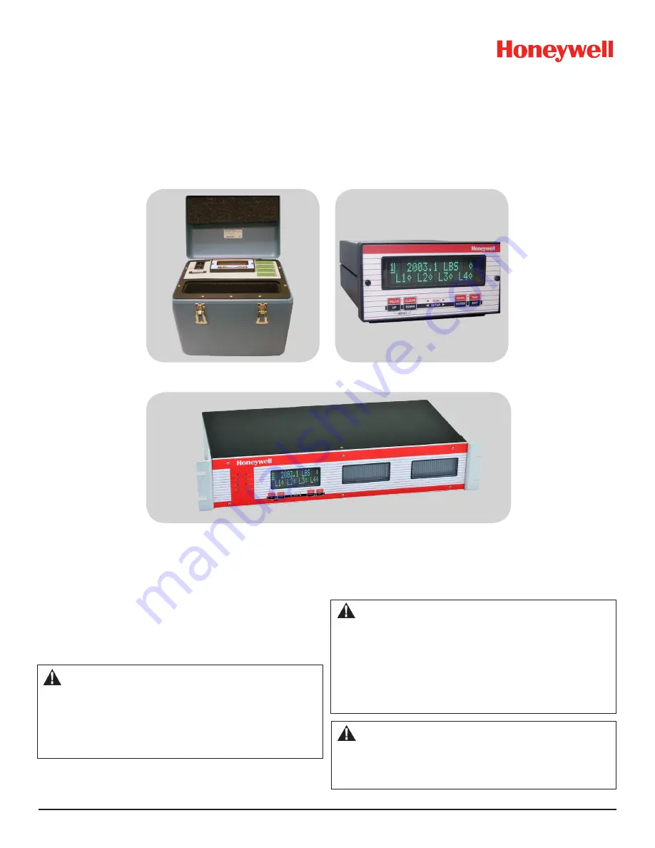
Models SC2000, SC2001, SC3004

Signal Conditioning Self-Calibrating Digital Indicators

Test and Measurement

Rev. G

008-0608-00

SC2001

SC2000

SC3004

Содержание SC2000

Страница 1: ... stop devices or in any other application where failure of the product could result in personal injury Failure to comply with these instructions could result in death or serious injury CAUTION Only qualified service trained personnel who are aware of the hazards involved should remove the cover from the instrument or connect external wiring to the instrument Installation Instructions Models SC2000...

Страница 2: ...xiting the SETUP Menu mode 7 3 5 3 Moving Through SETUP Menus 8 3 5 4 Exiting the SETUP Menu mode 8 Chapter 4 Chassis Models 9 4 1 Introduction 9 4 2 Specifications 9 4 3 Model SC2000 10 4 3 1 External Arrangement 10 4 3 2 Rear Panel 11 4 3 3 Panel Mounting 11 4 3 4 Rack Mounting 11 4 3 5 Bench Mounting 11 4 3 6 Case Removal 11 4 3 7 Internal Arrangement 12 4 3 8 Cleaning 12 4 3 9 Vehicle Power Op...

Страница 3: ...28 10 5 Channel Menu 29 10 5 1 OPERATION Sub Menu 29 10 5 2 DISPLAY SETUP Sub Menu 29 10 5 3 AUXn FUNCTION Menu Items 30 10 5 4 CALIBRATION TYPE Menu Item 31 10 5 5 CALIBRATION DATA Sub Menu 32 10 5 6 CALIBRATE Menu Item 33 10 5 7 DAC SETUP Sub Menu 34 10 5 8 SIGNATURE MODULE Sub Menu 35 10 5 9 DIAGNOSTICS Sub Menu 36 10 6 Analog Output Configuration 36 10 6 1 Identifying the Output Type 36 10 6 2...

Страница 4: ...l Installed 65 13 1 2 Second Channel Installed 65 13 1 3 Third Channel Installed 65 13 1 4 Fourth Channel Installed 65 13 2 Wiring 65 13 3 Setup Procedure 65 13 4 Specifications 65 13 5 Channel Menu 66 13 5 1 DIAGNOSTICS Sub Menu 66 Chapter 14 DAC Output Channel 66 14 1 Features 66 14 2 Wiring 66 14 3 Setup Procedure 67 14 4 Specifications 67 14 5 Channel Menu 67 14 5 1 DAC SETUP Sub Menu 67 14 5 ...

Страница 5: ...ransducer Connection to Strain Gage Input Channel 27 Figure 10 2 Shunt Calibration Resistor Location 33 Figure 10 3 Digital to Analog Output Jumper Locations 37 Figure 11 2 Digital to Analog Output Jumper Locations 46 Figure 12 1 Bi polar Voltage Amp Connection to High Level Input Channel 49 Figure 12 2 3 wire Voltage Amp Connection to High Level Input Channel 50 Figure 12 3 3 wire Voltage Amp w S...

Страница 6: ...put Channel Pin Connections 66 Table 18 1 SETUP Menu 77 Table 18 2 System Menu 78 Table 18 3 LIMIT Menu 79 Table 18 4 SERIAL COMMUNICATIONS Menu 79 Table 18 5 DISPLAY Menu for Models SC2000 SC2001 79 Table 18 6 Display Menu for Model SC3004 79 Table 18 7 Strain Gage Input Channel Menu 80 Table 18 7 Strain Gage Input Channel Menu continued 81 Table 18 8 ac ac LVDT Input Channel Menu 82 Table 18 8 a...

Страница 7: ...s SC2000 SC2001 and SC3004 Further information about customer specific programming and setup will be explained on the Customer Information Sheet that is provided with every instrument 1 1 2 Conventions This manual uses the following conventions to present informa tion TEXT IN BRACKETS The label of a front panel button DISPLAY Text that appears on the display such as error messages or menu items In...

Страница 8: ...teen with versatile setup Automatic setup calibration and scaling of strain gage sen sors through the use of Signature Calibration Field selectable digital low pass filtering damping on each Input channel Up to 50 000 part resolution Field selectable five six or seven digit 9 999 999 maxi mum display RS 232 communications standard RS 485 optional Local or remote setup using the RS 232 or RS 485 po...

Страница 9: ...a area unalterable by the customer can be copied back into the User Calibration Data 1 4 3 Information Stored The following information is stored inside transducers equipped with Signature Calibration Full scale mV V The full scale millivolt per volt mV V rating of the transducer when its full load is applied also called calibration factor Shunt Cal mV V The millivolt per volt output of the transd...

Страница 10: ... to the On position The instrument enters its INITIALIZE mode that lasts a few sec onds per channel As each channel in the instrument is initial ized the transducer s serial number may be seen on the display if the transducer has a Signature Calibration Module in it NOTICE If the channel s display flashes APPLY 00000 or some other load value the instrument has detected a transducer other than the ...

Страница 11: ...ers to Their Channels You can skip this step if You are using a transducer equipped with Signature Calibra tion or The transducer and instrument were purchased together and set up by Honeywell Otherwise you must choose a calibration method e g Shunt Calibration mV V Calibration or Known Load Calibration ap propriate for your application and use the SETUP menu for that channel to calibrate the chan...

Страница 12: ...xample a Strain Gage amplifier channel will use the format below 1p 00000 PSIG where Channel number 1 is the channel number Value type The next character indicates the nature of the following value A blank character indicates the tracking value The instrument is tracking the signal continuously updating the display in response to the signal from the trans ducer A p character indicates the peak val...

Страница 13: ...ts Models SC2000 SC2001 A symbol on the right side of a channel s display indicates tare is off for that channel a symbol indicates tare is on If the lower line of the display is configured with the DISPLAY MENU LOWER MODE menu item as LIMIT 01 04 then the lower line will monitor the status of Limits 1 2 3 and 4 A symbol indicates a limit is deactivated a symbol indicates a limit is activated For ...

Страница 14: ...through available menus sub menus or menu items ENTER Select a menu sub menu or menu item EXIT If changing a setting abandons changes to a menu item otherwise leaves the SETUP mode To change the setting of a menu item Press ENTER to display the current setting which is pre ceded by the character Press UP or DOWN until you see the setting you want To abandon changes press EXIT To accept the new set...

Страница 15: ... 2 Specifications Model SC2000 Model SC2001 Model SC3004 GENERAL Physical channels 1 to 4 1 to 4 1 to 14 Virtual channels 8 8 8 Case material Aluminum Aluminum Aluminum PHYSICAL Form factor 3 8 DIN suitcase 2U rack Mounting bench panel or rack portable rack DISPLAY characters line 16 16 20 lines display 2 2 4 displays 1 1 1 2 or 3 Display type Vacuum Fluorescent Vacuum Fluorescent Vacuum Fluoresce...

Страница 16: ...of the ac powered SC2000 is given below Figure 4 1 External Arrangement of ac powered SC2000 8 6 2 8 2 6 5 6 5 3 12 PIN CHANNEL 25 PIN SYSTEM IEC POWER ENTRY VACUUM FLUORESCENT DISPLAY 16 CHARACTER DUAL LINE 66mm 71mm 218mm 135mm 142mm CONNECTOR CONNECTOR MODULE CABLE SHIELD CONNECTION SCREW SC SERIES 0123456789ABCDEF 0123456789ABCDEF VALUE UP CLEAR DOWN TARE EXIT ENTER CHAN ...

Страница 17: ...g a single SC2000 into a 19 2U rack It includes the Panel Mounting Jacks described above as well as the 19 rack panel 4 3 5 Bench Mounting If bench mounting the instrument you may want the optional car rying handle bench stand order code AA926 4 3 6 Case Removal WARNING Disconnect the power cord and all cables from the instrument before attempting to remove the case Failure to comply with these in...

Страница 18: ...he Hardware Input Output Channel Boards plug into the remaining four slots of the SensoBus Backplane Board 4 3 8 Cleaning Turn off the instrument and unplug all connectors Use a soft cloth or tissue and a mild cleaner Do not use liquid or aerosol cleaners Do not allow any cleaner inside the instrument 4 3 9 Vehicle Power Option Model SC2000 instruments are available with a vehicle power op tion fo...

Страница 19: ...red SC2001 is given below Figure 4 4 External Arrangement of AC powered Model SC2001 11 5 29 2cm 13 25 33 7cm 9 2 23 3cm UP DOWN ENTER EXIT 0123456789ABCDEF 0123456789ABCDEF VALUE SC SERIES CLEAR CHAN TARE STORAGE COMPARTMENT 11 0 L x 2 5 W x 8 5 D 28 0cm L x 6 3cm W x 21 6cm D 12 PIN CHANNEL CONNECTORS MODULE IEC POWER ENTRY 16 CHARACTER DUAL LINE VACUUM FLUORESCENT DISPLAY 25 PIN SYSTEM CONNECTO...

Страница 20: ...el SC2000 Case Removal on page 11 4 4 5 Internal Arrangement See the Model SC2000 Internal Arrangement on page 12 4 4 6 Cleaning Turn off the instrument and unplug all connectors Use a soft cloth or tissue and a mild cleaner Do not use liquid or aerosol cleaners Do not allow any cleaner inside the instrument 4 4 7 Vehicle Power Option The Model SC2001 is available with a vehicle power option for o...

Страница 21: ...HIJ 0123456789ABCDEFGHIJ 0123456789ABCDEFGHIJ 0123456789ABCDEFGHIJ 4X 250 2X 125 CABLE SHIELD CONNECTION SCREWS QTY 4 FAN MOUNTING SCREWS DO NOT REMOVE MADE IN USA 17 18 125 19 4X 875 2X 1 75 3 5 9 125 8 875 4 5 2 Rear Panel The pinout for the 25 pin System connector is provided later in this chapter The pinouts for the individual channels are located in the chapter for that channel 4 5 3 Panel Mo...

Страница 22: ...ve the black case cover from the instrument Step 5 Remove eight Phillips screws from the rear panel including the two cable shield connection screws NOTE Do not remove the four screws which secure the cooling fan to the rear panel Step 6 Remove the rear panel 4 5 6 Rear Panel The pinout for the 25 pin System connector is provided later in this chapter 4 5 7 Internal Arrangement User installable pr...

Страница 23: ... Function Input 2 Clear Peak Valley Limits Input 19 10 FUNC 1 Function Input 1 Tare Off for all channels Input 19 11 FUNC 0 Function Input 0 Input 19 12 RS 485 TB RS 485 Transmit B Output 7 13 RS 485 TA RS 485 Transmit A Output 7 14 L1 Limit 1 Output Open Collector Output 19 15 L2 Limit 2 Output Open Collector Output 19 16 L3 Limit 3 Output Open Collector Output 19 17 L4 Limit 4 Output Open Collec...

Страница 24: ...e them as you would a dry relay contact with the following restrictions The voltage applied must be dc The polarity of the dc voltage must be observed Maximum voltage 50 Vdc Maximum power 2 0 W When Limits 1 2 3 or 4 are activated the corresponding open collector Limit Output pin on the System connector will be con nected to the DGND Digital Ground pin However a SensoCode program running on a Math...

Страница 25: ...vice all of the channels In the RUN mode the chassis reads each channel s track peak and valley value sequentially After each channel has been serviced the limits are processed The value displayed is obtained from the last execution of the RUN mode prior to entering the SETUP menu mode If you enter the SETUP mode immediately after power up the display will read NOT AVAILABLE 6 2 4 INSTALL CHANNEL ...

Страница 26: ...d by the address jumpers being set incorrectly or if the card is not physically inside the chassis Virtual Channel Installation Procedure Use the following procedure to install a Virtual Channel 1 Enter the SETUP menu mode then select SYSTEM MENU INSTALL CHANNEL The instrument will then present a menu of card types available for installation 2 Select the card type of the card you wish to install A...

Страница 27: ...ssions only one device should respond to a particular message Therefore every device on the loop must have a unique address If you have an instrument with more than one channel transmis sion must be addressed to the appropriate channel within the instrument 7 3 2 Parameters All SC instruments use no parity 8 data bits and 1 stop bits N 8 1 for serial communications Baud rates available are 300 600...

Страница 28: ...tely transmits the message ADDRESS nn TEST where nn is the two character address of the instrument Then the message MESSAGE SENT is shown on the display This helps detect wiring or other problems with serial communications from the instrument to the computer or PLC 7 4 7 LEAVE MENU Menu Item When the menu item is displayed press ENTER to leave this menu Press EXIT to return to the RUN mode ...

Страница 29: ... menu item is set to CHANNEL To change whether the channel s track peak or valley data value is displayed on power up use the channel s OPERATION POWER ON SOURCE menu item 8 2 3 LOWER MODE Menu Item Determines what is displayed on the lower line The choices are BLANK means that nothing is displayed LIMIT 01 04 means that the status of Limit 1 Limit 2 Limit 3 and Limit 4 are displayed as described ...

Страница 30: ...tions occur If the display is monitoring the channel of this Relay Output channel the display will indicate the status of these limits On a Model SC3004 the front panel light for the limit will illuminate The relay for the limit on this Relay Output channel will acti vate A Relay Output channel can be installed for Limits 9 10 11 and 12 When these limits are activated the following actions occur I...

Страница 31: ...specifies when to activate the limit relative to the set point and return point The options for this menu item are SIGNAL SETPOINT means the limit will activate when the signal is higher than the set point SIGNAL SETPOINT means the limit will activate when the signal is lower than the set point SIGNAL INSIDE means the limit will activate when the signal is in between the set point and the return p...

Страница 32: ...cepts millivolt signals from strain gage transducers These millivolt signals are digitized converted into engineering units and placed into the track peak and valley data values of the channel Setup and calibration of the channel can be made manually through the SETUP mode or automatically if the trans ducers are equipped with Signature Calibration See What is Signature Calibration on page 3 The a...

Страница 33: ... activate 10 12 bottom AUX2 Auxiliary Function 2 connect to pin 10 to activate 10 The Analog Output and Analog Return pins are electrically iso lated from all other pins on the instrument The maximum recommended cable length to a Signature Module is 100 feet 30m NOTICE If you are not using remote sensing of excitation jumper Sense to Excitation and Sense to Excitation If nothing is connected to Se...

Страница 34: ...b menu Step 4 Perform the calibration Otherwise use the CALIBRATE menu item to start the calibra tion process You will be prompted to apply loads to the transducer as required 10 4 Specifications TRANSDUCER INPUT Transducer type full bridge strain gage Excitation voltage 5 Vdc or 10 Vdc short circuit pro tected with sensing Transducer full scale output 0 5 to 11 0 mV V 5V excitation 0 5 to 5 5 mV ...

Страница 35: ...ions Frequency Response Step Re sponse ms typical Resolution counts not including min 10 overrange underrange capability 002 HERTZ FAST 40 50000 002 HERTZ 440 50000 008 HERTZ 110 25000 016 HERTZ 55 20000 032 HERTZ 28 10000 050 HERTZ 16 5000 100 HERTZ 8 5000 250 HERTZ 3 2000 500 HERTZ 2 2000 800 HERTZ 2 2000 POWER ON SOURCE Menu Item This menu selects which value is displayed by the channel when fi...

Страница 36: ...te Display averaging does not affect the channel s analog output or its peak valley detection which will proceed at the speed selected by the OPERATION FREQ RESPONSE menu item The choices are ON means that the display will update four times each sec ond The channel s values will be averaged for 1 4 second then displayed OFF means that the channel s display will update as quickly as possible 10 5 3...

Страница 37: ... SHUNT CAL means Shunt Calibration First you are prompted to apply the load entered in the ZERO SCALE VAL UE register Next the instrument inserts a known precision resistor into the transducer circuit which causes a predict able apparent signal The instrument then takes a reading and adjusts itself using the SHUNT CAL VALUE register TYPE MV V CAL means Millivolt per Volt Calibration First you are ...

Страница 38: ...s which is usually zero This menu item may be automatically updated by a transducer s Signature Module It is available only with the Shunt Calibration and mV V Calibration types SHUNT CAL VALUE Menu Item The shunt calibration value must be calculated by using informa tion found on the transducer s Certificate of Calibration and the following formula SHUNT CAL VALUE Shunt calibration output Full sc...

Страница 39: ... of the transduc er s full scale capacity KNOWN POINT 2 5 point 2 of 5 usually 25 of the transduc er s full scale capacity KNOWN POINT 3 5 point 3 of 5 usually 50 of the transduc er s full scale capacity KNOWN POINT 4 5 point 4 of 5 usually 75 of the transduc er s full scale capacity KNOWN POINT 5 5 point 5 of 5 usually 100 of the trans ducer s full scale capacity NOTICE To insure both correct ope...

Страница 40: ...ucer press ENTER Upon completion the display will indicate DONE and the instrument will return to the RUN mode If the CALIBRATION TYPE is 5 Point Known Load Calibration The display will read DOING 5POINT CAL and prompt you to APPLY 00000 UNIT where 00000 and UNIT are previously entered as KNOWN POINT 1 5 and DISPLAY UNITS When you have applied this load to the transducer press ENTER The display wi...

Страница 41: ...cally updated by a transducer s Signature Module If the UPDATE DAC SETUP menu item is OFF a transducer s Signature Module will not change this menu item 10 5 8 SIGNATURE MODULE Sub Menu UPDATE SIG MOD Menu Item Updates the information stored in the transducer s Signature Module with any new settings that is entered into the instrument with the SETUP menus The settings that will be updated are FULL...

Страница 42: ...ta obtained from either the Sig nature Module or a 3 Point or 5 Point Known Load Calibra tion to affect a channel s scaled values This is the recom mended option OFF will not allow linearization data to effect the channel s scaled values This is useful when diagnosing problems in a calibration procedure DISABLE CHANNEL Menu Item The options for this menu item are ON will bypass the INITIALIZE and ...

Страница 43: ...still see this message the Excitation EXC or Excitation EXC pins may be shorted to the Signal SIG or Signal SIG pins If you remove all load from the transducer and you get a numeric reading the transducer may have a high zero offset Use the channel s SETUP menu and set DIAGNOSTICS DISPLAY ADC to ON in the RUN mode this will allow the VALUE button to dis play raw A D readings as a percentage of its...

Страница 44: ...cept the presently applied load as 0 In situations where one can t apply 0 load to an absolute pressure transducer or a load cell with a pre load you can change the CALIBRATION DATA ZERO SCALE VALUE menu item from 0 to a load that can be applied For example 14 7 PSIA or the known pre load on the load cell Use the CALIBRATE menu item to perform a Known Load Cali bration with this new transducer Aux...

Страница 45: ...ovided NOTICE To use a dc dc LVDT with an SC instrument use a High Level Input channel instead of an ac ac LVDT Input channel 11 2 Wiring Connect your transducer to an ac ac LVDT Input channel by wiring it to the 12 pin connector of that channel The Customer In formation Sheet that shipped with the instrument describes which cards are installed in each channel The pin out for this connector is sho...

Страница 46: ...Once this point has been determined the transducer is physically clamped into position See Electrical Null and Transducer Mounting on page 45 Step 5 Perform the calibration Using the CALIBRATE menu item starts the calibration pro cess You will be prompted to apply displacements to the transducer as required 11 4 Specifications TRANSDUCER INPUT Transducer type full bridge AC AC LVDT Excitation Volt...

Страница 47: ...5000 100 HERTZ 8 5000 250 HERTZ 3 2000 500 HERTZ 2 2000 800 HERTZ 2 2000 NOTICE Your particular LVDT may have a lower frequency response than the ac ac LVDT Input channel POWER ON SOURCE Menu Item This menu selects which value is displayed by the channel when first entering the RUN mode The choices are TRACK means the live tracking value of the channel PEAK means the highest value of the channel V...

Страница 48: ...tem The choices for this menu item are TYPE 2 POINT CAL means 2 Point Known Displacement Calibration You are prompted to apply the displacements to the transducer that were entered in the KNOWN POINT 1 2 and KNOWN POINT 2 2 registers This technique assumes that the transducer is linear throughout the entire stroke so the usual displacements used are zero scale and full scale TYPE 3 POINT CAL means...

Страница 49: ...nown Displacement Point 1 2 You may need to swap the Signal and Signal wires on the 12 pin channel connector to accomplish this 11 5 6 CALIBRATE Menu Item This menu item performs a calibration according to what was en tered in the CALIBRATION TYPE and CALIBRATION DATA menu items NOTICE Before performing a calibration the transducer must be connected to the instrument the must be selected see Menu ...

Страница 50: ...s tracking value the Analog Output will have the frequency response speci fied by the channel s FREQ RESPONSE menu item Otherwise the Analog Output will operate more slowly DAC SOURCE Menu Item This designates the data source of the channel monitored by the analog output Each channel has three data sources the live tracking value TRACK its highest value PEAK and its lowest value VALLEY The options...

Страница 51: ... 11 6 Electrical Null and Transducer Mounting 11 6 1 Overview The mechanical travel of an LVDT transducer is not the same as its usable measuring range All LVDTs exhibit some non linearity near the ends of its armature s mechanical travel To insure that the LVDT will be used in its linear measuring range its electri cal null point must be determined This electrical null point is the armature posit...

Страница 52: ...gure below 11 7 2 Channel Menu Items The Analog Output can be driven by any channel s track peak or valley value See the Channel Menu section earlier in this chapter for a com plete listing of SETUP menu items available on the DAC SETUP sub menu 11 7 3 Output Selection Jumpers located on the channel s circuit board determine what outputs are generated when the value selected to drive the Ana log O...

Страница 53: ... or cur rent that the channel is equipped with see Identifying the Output Type on page 46 Use the DIAGNOSTICS DAC FULL SCALE and DIAGNOSTICS DAC ZERO SCALE menu items to force the Analog Output to a known output Then adjust your readout device panel meter PLC or data acquisition system to match Check the output selection jumpers see Output Selection on page 46 Auxiliary Function Pins Not Operating...

Страница 54: ...ed in CALIBRATION TYPE Menu Item on page 59 Two rear panel control inputs can be field configured for such functions as remote tare disabling peak valley detection and clearing the peak valley values A voltage or current digital to analog output is also provided 12 2 Wiring 12 2 1 Channel Connector Connect the amplified transducer in line amplifier or dc dc LVDT to a High Level Input channel by wi...

Страница 55: ...el Input Channel NOTICE See Low Voltage dc dc LVDTs on page 55 for information on wiring Model DLB DLE and DLF low voltage dc dc LVDTs The High Level Input channel s Configuration Jumpers must be set as follows for proper operation See Excitation and Signal Jumpers on page 56 Excitation supply 15 Vdc Excitation supply 15 Vdc Signal type voltage Signal reference single ended 1 2 3 4 5 6 7 8 9 10 11...

Страница 56: ...t as follows for proper operation See Excitation and Signal Jumpers on page 56 Excitation supply 28 Vdc Excitation supply GND Signal type voltage Signal reference differential Figure 12 2 3 wire Voltage Amp Connection to High Level Input Channel 1 2 3 4 5 6 7 8 9 10 11 12 EXCITATION SHUNT CAL 1 SHUNT CAL 2 EXCITATION SIGNAL SIGNAL ANALOG OUTPUT ANALOG OUTPUT N C DGND AUX1 AUX2 DESIGNATION PIN CABL...

Страница 57: ...See Excitation and Signal Jumpers on page 56 Excitation supply 28 Vdc Excitation supply GND Signal type voltage Signal reference differential Figure 12 3 3 wire Voltage Amp w Single Wire Shunt Cal Connection to High Level Input Channel 1 2 3 4 5 6 7 8 9 10 11 12 EXCITATION SHUNT CAL 1 SHUNT CAL 2 EXCITATION SIGNAL SIGNAL ANALOG OUTPUT ANALOG OUTPUT N C DGND AUX1 AUX2 DESIGNATION PIN CABLE SHIELD C...

Страница 58: ...ws for proper operation See Excitation and Signal Jumpers on page 56 Excitation supply 28 Vdc Excitation supply GND Signal type current Signal reference single ended 1 2 3 4 5 6 7 8 9 10 11 12 EXCITATION SHUNT CAL 1 SHUNT CAL 2 EXCITATION SIGNAL SIGNAL ANALOG OUTPUT ANALOG OUTPUT N C DGND AUX1 AUX2 DESIGNATION PIN CABLE SHIELD CONNECTION SCREW SUPPLY SHUNT CAL 1 OUTPUT OUTPUT IN LINE AMPLIFIER CAB...

Страница 59: ...annel s Configuration Jumpers must be set as follows for proper operation See Excitation and Signal Jumpers on page 56 Excitation supply 28 Vdc Excitation supply GND Signal type current Signal reference single ended Figure 12 5 2 wire Current Amp w Buffered Shunt Cal Connection to High Level Input Channel 1 2 3 4 5 6 7 8 9 10 11 12 EXCITATION SHUNT CAL 1 SHUNT CAL 2 EXCITATION SIGNAL SIGNAL ANALOG...

Страница 60: ...3d internal amplifier single wire shunt cal The High Level Input channel s Configuration Jumpers must be set as follows for proper operation See Excitation and Signal Jumpers on page 56 Excitation supply 28 Vdc Excitation supply GND Signal type current Signal reference single ended Figure 12 6 2 wire Current Amp w Single Wire Shunt Cal Connection to High Level Input Channel 1 2 3 4 5 6 7 8 9 10 11...

Страница 61: ... See Excitation and Signal Jumpers on page 56 Excitation supply 12 Vdc Excitation supply GND Signal type voltage Signal reference single ended Figure 12 7 Low Voltage dc dc LVDT Connection to High Level Input Channel 1 2 3 4 5 6 7 8 9 10 11 12 EXCITATION SHUNT CAL 1 SHUNT CAL 2 EXCITATION SIGNAL SIGNAL ANALOG OUTPUT ANALOG OUTPUT N C DGND AUX1 AUX2 DESIGNATION PIN CABLE SHIELD CONNECTION SCREW UNR...

Страница 62: ...ns may result in product damage 12 4 Calibration Procedure If you are not familiar with operating the instrument in the SETUP menu mode see SETUP Menu mode on page 7 A listing of all menu items is given in Setup Menu Reference on page 77 Step 1 Wire the transducer to the channel s connector See Wiring on page 48 for details Step 2 Set the Excitation and Signal jumpers appropriate for the transduce...

Страница 63: ...same as input when driven by the same channel s tracking data 1 Total excitation current of all channels must not exceed 120 mA for Models SC2000 or SC2001 and 310 mA for Model SC3004 12 6 Channel Menu Each High Level Input channel is configured and calibrated via its channel menu Detailed instructions on operating the instru ment in the SETUP Menu mode can be found in SETUP Menu mode on page 7 A ...

Страница 64: ...ata values are displayed by the channel and transmitted via serial communications DISPLAY DIGITS Menu Item Selects the number of digits displayed by the channel The choices are 5 DIGIT BIPOLAR displays both positive and negative num bers with five full digits 99999 6 DIGIT UNIPLOAR displays positive numbers with six full digits 999999 and negative numbers with five full digits 99999 7 DIGIT UNIPOL...

Страница 65: ...ns that the peak and valley values will not be updated HIGH LOW CLEAR means that the peak and valley values are reset TARE ON activates the channel s Tare function resets it to zero TARE OFF deactivates the channel s Tare function As the Auxiliary Function pins are not isolated it is recommended that a push button switch or relay is used to connect these pins to the Digital Ground pin 12 6 4 CALIB...

Страница 66: ...pe affects what menu items ap pear in the CALIBRATION DATA sub menu 12 6 5 CALIBRATION DATA Sub Menu This enters the values that will be used by the instrument when it calibrates itself to the transducer The menu items that are displayed will change according to what the CALIBRATION TYPE is set for FULL SCALE VOLT or FULL SCALE CURR Menu Item The nominal transducer amplifier output when its full s...

Страница 67: ...ample the load applied at Known Load Point 2 2 must cause the transducer to produce a more positive voltage or current than at Known Load Point 1 2 These menu items are only available with the Known Load Cali bration types 12 6 6 CALIBRATE Menu Item This menu item performs a calibration according to what was en tered in the CALIBRATION TYPE and CALIBRATION DATA menu items NOTICE Before performing ...

Страница 68: ... the UP button and ENTER to select RETURN POINTS YES you may now apply the same loads again but in reverse order This will allow the instrument to measure and partially eliminate any hysteresis that may be present in the transducer After the loads have been applied again the display will indicate DONE and the instrument will return to the RUN mode 12 6 7 DAC SETUP Sub Menu This sub menu contains f...

Страница 69: ...affect a channel s scaled values This is the recom mended option OFF will not allow linearization data to effect the channel s scaled values This is useful when diagnosing problems in a calibration procedure DISABLE CHANNEL Menu Item The options for this menu item are ON will bypass the INITIALIZE and RUN modes of the chan nel The track peak and valley values of the channel are forced to 0 OFF wil...

Страница 70: ... get a numeric reading the transducer may have a high zero offset Use the Figure 12 9 Digital to Analog Output Jumper Locations channel s SETUP menu and set DIAGNOSTICS DISPLAY ADC to ON in the RUN mode this will allow the VALUE button to dis play raw A D readings as a percentage of its full scale If the raw A D readings display more than 10 when there is no load on the transducer the transducer h...

Страница 71: ... show the status of these limits In the SYSTEM CONFIGURATION sub menu channels of this type are identified as LIMIT 13 16 13 2 Wiring The pin out for the Relay Output channel s 12 pin connector is shown in the following table Table 13 1 Relay Output Channel Pin Connections Pin Label Function Ref Pin 1 top RELAY1 NC Relay 1 normally closed 2 2 RELAY1 C Relay 1 common 3 RELAY1 NO Relay 1 normally op...

Страница 72: ...is menu item are ON will turn the relay on OFF will turn the relay off Chapter 14 DAC Output Channel 14 1 Features The DAC Output channel uses a digital to analog converter to generate a voltage or current from any channel s track peak or valley value This type of channel is often used to provide a Math ematics Virtual channel with an analog output 14 2 Wiring Connect your readout instrument to a ...

Страница 73: ...enu Reference on page 77 14 5 1 DAC SETUP Sub Menu This sub menu contains four items that controls the analog output of the channel DAC CHANNEL Menu Item This chooses which channel will drive the Digital to Analog Con verter DAC output DAC SOURCE Menu Item This designates the data source of the channel monitored by the analog output Each channel has three data sources the live tracking value TRACK...

Страница 74: ...nn TYPE menu item where nn is the number of the channel If the channel s type is VOLTAGE DAC it has a voltage output If the channel s type is CURRENT DAC it has a current output Examining the channel s circuit board as shown in the figure below 14 6 2 Channel Menu Items The Analog Output can be driven by any channel s track peak or valley value See the Channel Menu section earlier in this chapter ...

Страница 75: ...NOSTICS DAC FULL SCALE and DIAGNOSTICS DAC ZERO SCALE menu items to force the Analog Output to a known output Then adjust your readout device panel meter PLC or data acquisition system to match Check the output selection jumpers see Output Selection on page 68 Check the DAC SETUP DAC ZERO SCALE and DAC SETUP DAC FULL SCALE menu items Sensitivity to EMI RFI To obtain maximum immunity to electromagn...

Страница 76: ...7 A diagram of all menus is located in Setup Menu Reference on page 77 LEFT CHANNEL Menu Item This specifies the channel that is displayed on the left half of the split display LEFT SOURCE Menu Item This lets you designate the data source of the channel moni tored by the left half of the split display Each channel has three data sources the live tracking value TRACK its highest value PEAK and its ...

Страница 77: ...mode see SETUP Menu mode on page 7 A listing of all menu item is given in Setup Menu Reference on page 77 Step 1 Examine the Supplemental Instructions Supplemental Instructions contain important information about what each Mathematics Channel does and what Func tion Inputs and or Limit Output pins of the System connector are used Step 2 Wire to the pins on the System connector See System Connector...

Страница 78: ...DISPLAY UNITS Menu Item Specifies the four character label that is displayed to the right of the channel s values This menu item doesn t change the mathe matical scaling of the channel s values that is determined by the CALIBRATION DATA FULL SCALE VALUE menu item When a character position is flashing press the UP or DOWN button to change the character Press ENTER to advance to the next character D...

Страница 79: ... 21 BLOWN STACK The instrument s software stack has overflowed Restart the instrument If this error per sists contact our Service department with the information found in the SYSTEM MENU SOFTWARE REV menu item Error 22 TYPE NOT FOUND The instrument has not been programmed to understand the type of channel Contact our Service department with the information found in the SYSTEM MENU SOFTWARE REV men...

Страница 80: ...d If this is a High Level Input Channel make certain that the Shunt Cal 1 and Shunt Cal 2 pins are connected to the correct pins of the transducer amplifier Error 43 BAD IDENT CRC A checksum failure has occurred when reading a channel s EEPROM Restart the instru ment Error 44 BAD FUNCTION The instrument has requested that the channel perform a function that it is not capable of Restart the instrum...

Страница 81: ...hat you have followed the procedure described in Electrical Null and Transducer Mounting on page 45 Error 62 SLAVE NAK The channel s microprocessor is responding to a message but it did not acknowledge it correctly Restart the instrument Error 67 LOADS NOT CLOSE During a 5 Point Known Load calibration you would typically apply loads at 0 25 50 75 and 100 of the transducer s full scale and optional...

Страница 82: ...4 BAD VALUE A Mathematics Virtual channel has attempted to get a value from a channel not installed in the instrument Error 85 UNREACHABLE GOTO The destination step of a Go to Instruction is beyond the end of the SensoCode pro gram The SensoCode program loaded in the Mathematics Virtual channel is invalid Error 87 GOTO NOT JUMP The SensoCode program contains a Go to Instruction that has not been c...

Страница 83: ...type CHANNEL 14 MENU menu varies according to channel type CHANNEL 15 MENU menu varies according to channel type CHANNEL 16 MENU menu varies according to channel type CHANNEL 17 MENU menu varies according to channel type CHANNEL 18 MENU menu varies according to channel type CHANNEL 19 MENU menu varies according to channel type CHANNEL 20 MENU menu varies according to channel type CHANNEL 21 MENU m...

Страница 84: ...EL 14 TYPE CHANNEL 15 TYPE CHANNEL 16 TYPE CHANNEL 17 TYPE CHANNEL 18 TYPE CHANNEL 19 TYPE CHANNEL 20 TYPE CHANNEL 21 TYPE CHANNEL 22 TYPE CHANNEL 23 TYPE LEAVE SUB MENU DIAGNOSTICS OUTPUT 1 PIN 14 ON page 19 OFF OUTPUT 2 PIN 15 ON OFF OUTPUT 3 PIN 16 ON OFF OUTPUT 4 PIN 17 ON OFF INPUT TEST page 19 SCAN TIME page 19 LEAVE SUB MENU INSTALL CHANNEL 65 STRAIN GAGE V page 19 66 STRAIN GAGE I 67 HIGH ...

Страница 85: ...E SIGNAL SETPOINT page 25 SIGNAL SETPOINT SIGNAL INSIDE SIGNAL OUTSIDE LIMIT LATCHING ON page 26 OFF LIMIT CHANNEL page 26 LIMIT SOURCE TRACK page 26 PEAK VALLEY LEAVE MENU DISPLAY MENU POWERON CHANNEL page 23 LEAVE MENU DISPLAY MENU UPPER CHANNEL page 23 LOWER CHANNEL page 23 LOWER MODE BLANK page 23 LIMITS 01 04 CHANNEL DISPLAY DISABLE ON page 23 OFF LEAVE MENU Table 7 13 SERIAL COMMUNICATIONS M...

Страница 86: ...age 29 PEAK VALLEY LEAVE SUB MENU DISPLAY SETUP DISPLAY DIGITS 5 DIGIT BIPOLAR page 29 6 DIGIT UNIPOLAR 7 DIGIT UNIPOLAR DISPLAY DECPT 99999 page 29 9999 9 999 99 99 999 9 9999 99999 DISPLAY COUNTBY 00001 page 30 00002 00005 00010 00020 00050 00100 00200 DISPLAY UNITS page 30 DISPLAY AVERAGE ON page 30 OFF LEAVE SUB MENU AUX1 FUNCTION DISABLED page 30 TRACK HOLD HIGH LOW HOLD HIGH LOW CLEAR TARE O...

Страница 87: ...VALUE KNOWN LOAD POINT 1 5 KNOWN LOAD POINT 2 5 KNOWN LOAD POINT 3 5 KNOWN LOAD POINT 4 5 KNOWN LOAD POINT 5 5 LEAVE SUB MENU CALIBRATE page 33 DAC SETUP DAC CHANNEL page 34 DAC SOURCE TRACK PEAK VALLEY DAC ZERO SCALE DAC FULL SCALE LEAVE SUB MENU SIGNATURE MODULE UPDATE SIG MOD NO page 35 YES DEFAULT SIG MOD NO YES UPDATE DAC SETUP NO YES LEAVE SUB MENU DIAGNOSTICS DAC FULL SCALE page 36 DAC ZERO...

Страница 88: ... 41 PEAK VALLEY LEAVE SUB MENU DISPLAY SETUP DISPLAY DIGITS 5 DIGIT BIPOLAR page 41 6 DIGIT UNIPOLAR 7 DIGIT UNIPOLAR DISPLAY DECPT 99999 page 41 9999 9 999 99 99 999 9 9999 99999 DISPLAY COUNTBY 00001 page 41 00002 00005 00010 00020 00050 00100 00200 DISPLAY UNITS page 42 DISPLAY AVERAGE ON page 42 OFF LEAVE SUB MENU AUX1 FUNCTION DISABLED page 42 TRACK HOLD HIGH LOW HOLD HIGH LOW CLEAR TARE ON T...

Страница 89: ...age 42 KNOWN LOAD POINT 1 5 KNOWN LOAD POINT 2 5 KNOWN LOAD POINT 3 5 KNOWN LOAD POINT 4 5 KNOWN LOAD POINT 5 5 LEAVE SUB MENU CALIBRATE page 43 DAC SETUP DAC CHANNEL page 44 DAC SOURCE TRACK PEAK VALLEY DAC ZERO SCALE DAC FULL SCALE LEAVE SUB MENU DIAGNOSTICS DAC FULL SCALE page 44 DAC ZERO SCALE VERSION INFO DISPLAY ADC ON OFF LINEARIZATION ON OFF LEAVE SUB MENU LEAVE MENU ...

Страница 90: ...e 58 PEAK VALLEY LEAVE SUB MENU DISPLAY SETUP DISPLAY DIGITS 5 DIGIT BIPOLAR page 58 6 DIGIT UNIPOLAR 7 DIGIT UNIPOLAR DISPLAY DECPT 99999 page 58 9999 9 999 99 99 999 9 9999 99999 DISPLAY COUNTBY 00001 page 58 00002 00005 00010 00020 00050 00100 00200 DISPLAY UNITS page 58 DISPLAY AVERAGE ON page 59 OFF LEAVE SUB MENU AUX1 FUNCTION DISABLED page 59 TRACK HOLD HIGH LOW HOLD HIGH LOW CLEAR TARE ON ...

Страница 91: ...libration type ZERO SCALE VALUE SHUNT CAL VALUE KNOWN LOAD POINT 1 5 KNOWN LOAD POINT 2 5 KNOWN LOAD POINT 3 5 KNOWN LOAD POINT 4 5 KNOWN LOAD POINT 5 5 LEAVE SUB MENU CALIBRATE page 61 DAC SETUP DAC CHANNEL page 62 DAC SOURCE TRACK PEAK VALLEY DAC ZERO SCALE DAC FULL SCALE LEAVE SUB MENU DIAGNOSTICS DAC FULL SCALE page 63 DAC ZERO SCALE VERSION INFO DISPLAY ADC ON OFF LINEARIZATION ON OFF DISABLE...

Страница 92: ...1 ON page 66 OFF RELAY 2 ON page 66 OFF RELAY 3 ON page 66 OFF RELAY 4 ON page 66 OFF LEAVE SUB MENU LEAVE MENU CHANNEL xx MENU DAC SETUP DAC CHANNEL page 67 DAC SOURCE TRACK PEAK VALLEY DAC ZERO SCALE DAC FULL SCALE LEAVE SUB MENU DIAGNOSTICS DAC FULL SCALE page 68 DAC ZERO SCALE LEAVE SUB MENU LEAVE MENU CHANNEL xx MENU LEFT CHANNEL page 70 LEFT SOURCE TRACK page 70 PEAK VALLEY RIGHT CHANNEL pag...

Страница 93: ... 71 VIEW COMMANDS COMMAND 0 page 72 COMMAND 1 COMMAND 2 COMMAND 3 COMMAND 4 COMMAND 5 COMMAND 6 COMMAND 7 LEAVE SUB MENU DISPLAY SETUP DISPLAY DIGITS 5 DIGIT BIPOLAR page 72 6 DIGIT UNIPOLAR 7 DIGIT UNIPOLAR DISPLAY DECPT 99999 page 72 9999 9 999 99 99 999 9 9999 99999 DISPLAY COUNTBY 00001 page 72 00002 00005 00010 00020 00050 00100 00200 DISPLAY UNITS page 72 DISPLAY AVERAGE ON page 72 OFF LEAVE...

Страница 94: ...ide 2 Communications Protocol 21 CONFIGURATION Sub Menu 19 Connecting Transducerl 4 Customer Information Sheet 2 D DAC Output Channel 66 86 DAC SETUP AC AC LVDT Input 44 DAC SETUP DAC Output Channel 67 DAC SETUP High Level Input 62 DAC SETUP Strain Gage Input 34 DEFAULT CHANNEL Menu Item 20 DELETE CHANNEL Menu Item 20 DIAGNOSTICS Sub Menu 19 DIAGNOSTICS AC AC LVDT Input 44 DIAGNOSTICS DAC Output C...

Страница 95: ... 57 OPERATION Strain Gage Input 29 Output Selection 36 46 63 Output Selection DAC Output Channel 68 Output Type 36 46 63 Output Type DAC Output Channel 68 P POWER ON CHANNEL Menu Item 23 POWER ON SOURCE Mathematics Virtual Channel 72 Problems and Solutions 37 47 64 69 R Relay Output Channel 65 86 Required Parts and Information 4 RS 232 vs RS 485 21 RUN Mode Display 6 RUN Mode 6 S SC Series Channel...

Страница 96: ...a particular purpose In no event shall Honeywell be liable for consequential special or indirect damages While we provide application assistance personally through our literature and the Honeywell web site it is up to the customer to determine the suitability of the product in the application Specifications may change without notice The information we supply is believed to be accurate and reliable...

Отзывы: