background image

10

Related Documents

This document is a necessary prerequisite for understanding the Honeywell Rapid Eye™ 
Multi-Media LT DVR. For more information, please refer to the documents listed in the table 
below (included on the Documentation CD that came with your Rapid Eye LT unit). Find the 
latest versions of these documents on the Honeywell Video website (see 

www.honeywellvideo.com/products/recorders/

).

Typographical Conventions

This document uses the following typographical conventions:

Document title

Description

Rapid Eye™ Multi-Media Digital 
Video Recorder System 
Administrator Guide

This guide is written for system administrators of Rapid Eye Multi-Media 
DVRs. This guide covers setting up and managing single and multiple DVR 
systems, both locally and remotely.

Rapid Eye™ Multi-Media Digital 
Video Recorder Remote View 
Operator Guide

This guide is written for remote operators of Rapid Eye Multi-Media DVRs. 
This guide covers using the View application to view live and recorded 
video, search for recorded motion, event, and alarm video, make video 
clips, and set up site tours.

Rapid Eye™ Multi-Media Digital 
Video Recorder System Common 
Operator Guide

Written for the security operator who uses the software for daily 
surveillance tasks, including live monitoring of events and alarms, and 
after-the-fact event searching.

Rapid Eye™ Multi-Media LT Quick 
Start Guide

This guide is a quick reference for setting up a new Honeywell Rapid Eye 
DVR system.

Font

What it represents

Example

Helvetica

Keys on the keyboard

Press 

Ctrl+C

Lucida

Values of editable fields that are mentioned in the body text of 
the document for reference purposes, but do not need to be 
entered as part of a procedure

The 

Time from

 field can be set to 

Hours:Minute:Seconds

.

Text strings displayed on the screen
Syntax

The message 

Unauthorized 

displays.

(object) entered

Swiss721 
BT Bold

Words or characters that you must type. The word “enter” is 
used if you must type text and then press the 

Enter

 or 

Return


key.

Enter the 

password

.

Menu titles and other items you select

Double-click 

Open

 from the 

File

 menu.

Buttons you click to perform actions

Click 

Exit

 to close the program.

Italic

Placeholders: words that vary depending on the situation

user name

Cross-reference to external source

Refer to the 

System Administrator Guide

.

Cross-reference within document

See 

Chapter 2, Installation

.

Содержание Rapid Eye LT

Страница 1: ...Document 800 07766V1 Rev A 02 11 Installation Guide Rapid Eye LT Digital Video Recorder ...

Страница 2: ......

Страница 3: ...Installation Guide ...

Страница 4: ...isions A 11 10 New document based on 800 02607V3 rev A for Rapid Eye Multi Media V9 V1 Rev A 02 11 Revision of 800 07766 Rev A No major content changes Changes include PAL RE LT units no longer supporting the internal modem 4 ...

Страница 5: ...hapter 3 Quick Test for Remote Video describes a quick test to confirm that all the Rapid Eye hardware and software is working properly Chapter 4 Audio identifies procedures to check for audio interference and to monitor and record audio data Chapter 5 Site Hardware shows how to add hardware to a Multi Media LT DVR and then use the software to configure the hardware Appendix A Frequently Asked Que...

Страница 6: ...s and to maintain your warranty FCC Compliance Statement Information to the User This equipment has been tested and found to comply with the limits for a Class A digital device Pursuant to Part 15 of the FCC Rules these limits are designed to provide reasonable protection against harmful interference in a commercial environment This equipment generates uses and can radiate radio frequency energy a...

Страница 7: ...OTICE This equipment meets telecommunications network protective operational and safety requirements as prescribed in the appropriate Terminal Equipment Technical Requirements document s This is confirmed by marking the equipment with the Industry Canada certification number The Department does not guarantee the equipment will operate to the user s satisfaction Before installing this equipment use...

Страница 8: ...ety of ITE EN61000 3 2 2006 A2 2009 Power line Harmonics EN61000 3 3 2008 Flicker Specification Summary Specification Description Operating Environment Temperature 40 F to 104 F 5 C to 40 C EN 50130 5 Environmental Class 1 Power 100 240 V 50 60 Hz auto ranging Heat dissipation 410 BTU hr Interface Cable requirement Cables included with the unit are listed in Table 2 1 on page 23 Other connectors B...

Страница 9: ...r Be sure to have the model number serial number and the nature of the problem available for the technical service representative Prior authorization must be obtained for all returns exchanges or credits Items shipped to Honeywell without a clearly identified Return Merchandise Authorization RMA number may be refused Local video output Television monitor for public display VGA monitor for operatio...

Страница 10: ...s Rapid Eye Multi Media Digital Video Recorder System Common Operator Guide Written for the security operator who uses the software for daily surveillance tasks including live monitoring of events and alarms and after the fact event searching Rapid Eye Multi Media LT Quick Start Guide This guide is a quick reference for setting up a new Honeywell Rapid Eye DVR system Font What it represents Exampl...

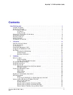
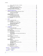
Страница 11: ...tor 22 Background Information 22 2 Installation 23 Before You Begin 23 Unpack Everything 23 Overview of the Installation Procedure 24 Recording the Installation Details 25 Rear Panel Connections 25 Connecting a Camera 26 Rapid Dome or Rapid Dome Gold Dome Systems 27 Securing a Camera 27 Powering the Multi Media LT DVR 27 Powering Up 28 Powering Down 28 Unit Recovery 29 Rapid Eye LT Unit Installati...

Страница 12: ...ng Audio Offsite 47 Monitoring and Recording Audio 48 Enabling Talking to a Site 48 Onsite Audio Using LocalView 48 Disabling Audio for LocalView 48 5 Site Hardware 49 Securing a Multi Media LT DVR 49 Connectors for Serial Communications 50 Hardware Options 51 Public Display Monitor 51 Using LocalView for Public Display 52 Connecting a PTZ Dome 52 ACUIX Camera 52 Many PTZ Domes on One Serial Commu...

Страница 13: ...tions 65 Rubber Feet and the Orientation of Unit Installations 65 Installing Rubber Feet for a Vertical Installation 66 Appendix D Site Information Checklists 67 Organization 67 Site Definition 67 Communications to DVR 68 Communications from DVR to Alarm Station 69 Audio 69 Video Camera Configuration 70 Sensor Hardware 70 Control Outputs 71 Serial Ports 71 Point of Sale POS Hardware 72 Index 73 ...

Страница 14: ...14 Contents ...

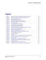
Страница 15: ...ection North American Units Only 35 Figure 3 1 Desktop Icon for the Admin Application 39 Figure 3 2 Running a Maintenance Session 40 Figure 3 3 Select a Site on the Sites Tab then Click Live 41 Figure 3 4 DVR Base IP Ports Remote Connection and Alarm Station 44 Figure 4 1 Audio Input to Multi Media LT DVR 45 Figure 4 2 Connecting Speakers 46 Figure 4 3 Audio Tab 47 Figure 5 1 Pin Order on Ports 1 ...

Страница 16: ...16 Figures ...

Страница 17: ...R Modem 36 Table 2 4 Media Options for Video Clips 37 Table 3 1 Default Transmission Control Protocol TCP Ports 43 Table 5 1 Wiring an RS 232 Cable for Serial Use 50 Table 5 2 Wiring an RJ45 Cable for Serial Use 50 Table 5 3 PTZ Drivers for Controllers and Domes 53 Table 5 4 Sensor Hardware 56 Table A 1 Installation FAQs 61 Table B 1 Recommended Maximum Length of Coaxial Cable 63 Table B 2 Coaxial...

Страница 18: ...18 Tables ...

Страница 19: ...dia LT DVR Note Experienced installers may wish to go directly to Chapter 2 Installation and or Chapter 5 Site Hardware LocalView and View Software A Multi Media LT DVR can be operated Without a personal computer PC Connect a VGA monitor and mouse directly to the DVR to use LocalView onsite With a PC for remote access using Admin and View software For more information see Chapter 2 Installation No...

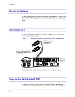
Страница 20: ...ing a Dial Up Connection in the Field on page 36 Powering the Multi Media LT DVR Honeywell recommends that you apply power to the Multi Media LT DVR through an uninterruptible power supply UPS For more information see Powering Up on page 28 SERIAL PORT 2 SERIAL PORT 1 VGA TELCO USB USB LAN IN OUT NOT USED 1 2 3 4 5 6 7 8 SPOT MONITOR VIDEO INPUTS COMMON SYS FAIL SYS GOOD FAULT RELAY 28V 3A MAX 1 G...

Страница 21: ...perating the DVR Remotely If you plan to perform a quick connection after the installation to connect remotely to Rapid Eye LT DVRs you should refer to the Rapid Eye Multi Media Digital Video Recorder System Administrator Guide and the Rapid Eye Multi Media Digital Video Recorder System Common Operator Guide for the necessary procedures Note After installing the Rapid Eye software documentation ab...

Страница 22: ...imator as needed and click Apply Options to obtain an estimate of your system s storage capacity See the Rapid Eye Multi Media Digital Video Recorder System Administrator Guide for more information on the storage estimator Background Information Caution Effective video feeds are a major component of any CCTV system Planning for camera position distance from subject angle and lighting can be as cri...

Страница 23: ...ceive will depend on your unique system requirements Your kit can include Table 2 1 Contents of Rapid Eye Hardware Kit 100 02557 Itema Part Power Cord North America only P8137 Network CAT5 cable RJ45 connections 2 m length K9530 Modem cable RJ11 North America only CB00173 Terminal block plug for FAULT RELAY 4 positions 3 5 mm K9531 4 3 Terminal block plugs for ALARM inputs and CONTROL outputs 8 po...

Страница 24: ...splay the RMA on the shipping carton 6 Return the packaged DVR to the location specified by your supplier Overview of the Installation Procedure After unpacking the DVR 1 Determine the best place to install and the ideal orientation of the Multi Media LT unit horizontal or vertical The unit is shipped ready to install in a horizontal position See Appendix C Horizontal and Vertical Unit Installatio...

Страница 25: ... PORT 3 SERIAL PORT 4 1 G G G G 2 3 4 5 G G G G 6 7 8 ALARM INPUTS ON OFF POWER 115 230V 50 60 Hz 5 3A Video inputs and outputs for cameras LT units can have 4 or 8 inputs outputs Spot monitor video output Power switch Alarm and control connectors Communication ports Serial ports 3 and 4 Serial ports 1 and 2 Table 2 2 Rear Panel Connectors Connector label Description VIDEO INPUTS BNC connectors fo...

Страница 26: ...2 4 volts maximum low level of 0 4 volts CONTROL OUTPUTS Screw terminal connectors for output and ground connection Control I O must be referenced to the ground of the Multi Media LT DVR Interface with devices such as lights sirens locks and so on TTL type The outputs do not directly drive devices they control relays that do so SERIAL PORT 1 4 Ports 1 2 RS232 Ports 3 4 RS485 POWER SWITCH Use the p...

Страница 27: ...VRs can auto range 100 240 V 50 60 Hz Caution This equipment shall be connected to a grounded earthed outlet Do NOT remove or defeat the ground pin of the 3 prong electrical plug For many cameras in a permanent installation you can use a power supply such as an HPTV2404UL 4 cameras or HPTV2416UL 16 cameras A Multi Media LT DVR should be connected to a dedicated ground circuit The outlet and breake...

Страница 28: ...he Multi Media LT DVR Note Honeywell recommends that you power the cameras before powering the Multi Media LT DVR Powering Down 1 Press the power switch on the back panel of the DVR 2 Unplug the Multi Media LT DVR from the uninterruptible power supply UPS or wall outlet Caution The power cord is the disconnect device Remove the appliance coupler connector to disconnect the equipment SERIAL PORT 2 ...

Страница 29: ...mpromised Caution If the unit is installed in a closed or multi unit rack assembly the operating ambient temperature of the rack environment may be greater than room ambient Therefore consideration should be given to installing the equipment in an environment compatible with the maximum ambient temperature Tma specified by the manufacturer The following guidelines must be followed when installing ...

Страница 30: ...sible condensation when moving units between rooms with extreme temperature changes Setting Up LocalView A PC mouse included and PC monitor not included are needed when using LocalView to operate a Rapid Eye Multi Media LT DVR LocalView is available while the DVR is running Exhaust and intake vents on the unit and enclosure should line up for proper air circulation The temperature at the unit inta...

Страница 31: ...B Mouse and Optional Keyboard to the DVR A USB mouse included and PC monitor not included are needed when using LocalView to operate a Rapid Eye Multi Media LT DVR A USB keyboard not included is optional 1 Connect the mouse included to a USB port on the rear panel of the Rapid Eye LT unit 2 The USB ports on the back panel of the DVR can also be used to connect a USB flash drive commonly called a m...

Страница 32: ...e Quick Setup Wizard and Help are not needed Remote Connection After an IP address has been assigned to the DVR a remote connection can be setup using the Admin application Refer to the Rapid Eye Multi Media Digital Video Recorder System Administrator Guide Note For dial up connections LocalView is not needed to help set up a remote connection Using the Virtual Keyboard Use the virtual keyboard Fi...

Страница 33: ...In Network Settings enable DHCP on the Multi Media LT unit see Figure 2 8 By default the Site Name in LocalView shows REM hyphen DVR serial number and includes the leading zeroes The DVR serial number is also printed on a sticker affixed to the DVR If you change the Site Name make a note of the new name for setting up a remote connection using the Admin software 2 Click Refresh 164 178 32 1 If you...

Страница 34: ...ep 2 Note DHCP can change an address if it is not reserved compromising future attempts to connect to the DVR Network Address Translation Using an Internet Router Match the DVR Gateway to the Internet Router Inside IP 1 In Network Settings use the virtual keyboard to enter the DVR IP Address as given out by the Network Administrator of the remote LAN 2 In the Gateway field use the virtual keyboard...

Страница 35: ... Dial up Connection North American Units Only 1 Using a standard telephone cable with RJ11 connectors plug one connector into the TELCO port on the DVR see Figure 2 10 164 178 32 1 SERIAL PORT 2 SERIAL PORT 1 VGA TELCO USB USB LAN IN OUT NOT USED 1 2 3 4 5 6 7 8 SPOT MONITOR VIDEO INPUTS COMMON SYS FAIL SYS GOOD FAULT RELAY 28V 3A MAX 1 G G G G 2 3 4 CONTROL OUTPUTS SERIAL PORT 3 SERIAL PORT 4 1 G...

Страница 36: ... a telephone line used by a Multi Media LT DVR Note For dial up connections LocalView is not needed to help set up a remote connection You are ready to power up the camera s and the Multi Media LT DVR See Powering the Multi Media LT DVR on page 27 DVR Internal Modem Default Settings Testing a Dial Up Connection in the Field Using a standard telephone line dial the number used to reach the DVR mode...

Страница 37: ...ve tray opens automatically 7 Remove the CD and shut the DVD drive tray Use of Media by the DVR for Clip Distribution Using LocalView After making a clip of video onsite you may distribute the clip either by Copying the clip to a USB memory stick Burning the clip to disk media using the DVD drive on the Multi Media LT DVR See Table 2 4 Clip Size A video clip file including audio and data can be as...

Страница 38: ...ing message appears You can reduce the size of a clip by removing video feeds or by shortening the clip Making and Copying a Clip from a PC Running View Operators who make video clips offsite using a PC running the View application can copy one clip or many using the hardware on the PC ...

Страница 39: ...ation of Rapid Eye LT DVRs Checklist for Admin Software Figure 3 1 Desktop Icon for the Admin Application Refer to the Rapid Eye Multi Media Digital Video Recorder System Administrator Guide about using the Admin application to Open the ports in your organization s firewall that are needed by Rapid Eye See Firewall Reference page 43 Install Rapid Eye Multi Media LT REM software How to install and ...

Страница 40: ...e session at the Rapid Eye site to check if the connection is set up After one Maintenance Session runs the site is ready for further configuration and operation 4 Check if the connected camera s in a powered ON state are showing video feeds 5 Set the time of the Rapid Eye LT DVR Figure 3 2 Running a Maintenance Session Obtaining Live Video Refer to the Rapid Eye Multi Media Digital Video Recorder...

Страница 41: ...d video at every half hour or so over a 24 hour period Sun The darkness of night or bright sunlight may indicate the need for changes in camera position or lighting For outdoor cameras it can be worthwhile to run such spot checks seasonally Direct sunlight at short times during the day such as daybreak can interfere with recording for cameras aimed east as can sundown for cameras pointing west Aft...

Страница 42: ...tion for Cameras Calibration of tamper detection requires that a System Administrator has set up tamper detection on a camera to trigger an alarm or to be logged and that an operator use LocalView or a remote operator use View Blind A camera can be blinded by too much light or too little To calibrate cover the camera with an opaque cloth or box or prop a strong light in front of the camera for mor...

Страница 43: ... stand or truck depot Firewall Reference Multi Media sessions live retrieval and alarm are sent to port 10 000 the DVR base IP port The value of the base port can be changed by a Multi SA For port functions see Table 3 1 Table 3 1 Default Transmission Control Protocol TCP Ports Porta Name Use Needed at 10 000b Base Live retrieval and alarm sessions Multi Media LT DVR operator station 10 001 Mainte...

Страница 44: ...44 Quick Test for Remote Video Figure 3 4 DVR Base IP Ports Remote Connection and Alarm Station ...

Страница 45: ...o a Multi Media LT DVR see Figure 4 1 Figure 4 1 Audio Input to Multi Media LT DVR IN OUT NOT USED SERIAL PORT 2 SERIAL PORT 1 VGA TELCO USB USB LAN IN OUT NOT USED 1 2 3 4 5 6 7 8 SPOT MONITOR VIDEO INPUTS COMMON SYS FAIL SYS GOOD FAULT RELAY 28V 3A MAX 1 G G G G 2 3 4 CONTROL OUTPUTS SERIAL PORT 3 SERIAL PORT 4 1 G G G G 2 3 4 5 G G G G 6 7 8 ALARM INPUTS ON OFF POWER 115 230V 50 60 Hz 5 3A Chan...

Страница 46: ... operator see Figure 4 2 TIP Place speakers away from microphones to avoid audio feedback Figure 4 2 Connecting Speakers Note The NOT USED connector is disabled Use the AUDIO OUT connector to connect an audio output device speakers Checking For Audio Interference Checking one s installation for hard to predict situations includes spot checking for Live audio Coordinate the testing of audio with fi...

Страница 47: ...nes and speakers Test loud alarms during the installation they can interfere with Multi Media LT audio Caution Placing a microphone or speaker close to a ringing alarm bell can render either ineffective the bell noise can mask the voice of an operator attempting to use the microphone The bell could also mask a voice coming from a speaker Loud alarms can interfere with microphones or a speaker when...

Страница 48: ...ng LocalView LocalView can be used to test or permanently monitor audio onsite 1 Using LocalView on the Audio Setup tab add a checkmark to the box for Channel 2 Right Used by Site Operator for Local Audio Monitoring The channel 2 Enable Record and name are not needed for monitoring audio by a LocalView operator and are removed from view The Gain controls remain available for both audio channels 2 ...

Страница 49: ...and heat sensors Aside from cameras and communications a Multi Media LT DVR can interface with many different types of hardware such as Sensors motion heat alarm and so on Relay triggered devices locks gates warning sirens and so on Alarm panel a fault relay offers a means to monitor the DVR operational status using an external device Point of sale POS hardware using text messaging over serial com...

Страница 50: ...ot place equipment such as a monitor directly on top of the Multi Media LT DVR Connectors for Serial Communications Ports 1 and 2 The wiring for the RS 232 connectors on a Multi Media LT DVR s Serial PORT 1 and PORT 2 is listed in Table 5 1 Figure 5 1 Pin Order on Ports 1 and 2 of a DB 9 Connector View into the DVR Ports 3 and 4 The wiring for the RJ45 connectors on a Multi Media LT DVR s Serial P...

Страница 51: ...lay Monitor A public display monitor can be set up on Multi Media LT DVRs independently of LocalView There is no need for converters between the monitor and the DVR 1 Mount a monitor where you plan to have it display a video feed For NTSC cameras use an NTSC video monitor for PAL cameras use a PAL monitor Do NOT place a monitor on top of the Rapid Eye unit 2 Connect a coaxial cable to the INPUT of...

Страница 52: ...Z dome an RS485 connector to one of the ports on a Multi Media LT DVR Serial ports 3 and 4 do not need a 232 485 converter Figure 5 3 Serial Ports 1 to 4 ACUIX Camera An ACUIX PTZ camera dome with Intellibus can be connected to a Rapid Eye Multi Media LT DVR and configured using Rapid Eye View software 1 Set ACUIX cameras to their Intellibus mode Intellibus PTZ SERIAL PORT 2 SERIAL PORT 1 VGA TELC...

Страница 53: ...s Consistent Port Attributes Honeywell recommends that if domes are to share a serial communications line installers should select domes that Function at the same settings for Baud Rate Data Bits Parity and Stop Bits Use the same PTZ drivers Caution Domes that require different PTZ drivers may not function as expected if they are installed on the same port serial communications line Configuring PT...

Страница 54: ... ALARM terminal strip one wire to the numbered terminal connection and the other wire to ground Caution To avoid short circuits ensure that bare wire is not visible at the rear panel Kalatel 9600 or 2400 Kalatel KTD312 Cyberdome Pelco D 4800 9600 or 2400 Pelco D Pelco P 2400 Pelco P Rapid Dome Orbiter 9600 RapidDome or Orbiter SensorMatic RS422 4800 SensorMatic RS422 Delta and Speed Ultrak using V...

Страница 55: ...and input 8 see Figure 5 4 4 You have the option of monitoring the activation of inputs and their deactivation by selecting Log and Alarm as needed 5 By default alarm control inputs are configured as NO normally open Click NC normally closed or EOL end of line as needed Figure 5 4 Input Configuration During a Maintenance Session Technical Notes Inputs to a Multi Media LT DVR Used by Hardware Devic...

Страница 56: ... a Multi Media LT DVR Tools You may need A slot screwdriver supplied The screws are slightly smaller than those for a 1 8 inch screwdriver A wire stripper Connector 1 From the hookup wire tips strip approximately 0 6 cm 1 4 inch of insulation 2 Insert each relay control wire to the screw type terminal connector on the CONTROL OUTPUTS terminal strip one wire to ground and the other wire to the numb...

Страница 57: ... Fault Relay circuitry and outputs to an alarm panel preset to warn your organization if a failure occurs An output can be configured to respond to a Response Schedule Fault Relay Hardware Figure 5 5 Connecting the DVR FAULT RELAY to an External Alarm Panel SERIAL PORT 2 SERIAL PORT 1 VGA TELCO USB USB LAN IN OUT NOT USED 1 2 3 4 5 6 7 8 SPOT MONITOR VIDEO INPUTS COMMON SYS FAIL SYS GOOD FAULT REL...

Страница 58: ...T DVR can be operated in a non condensing environment in temperatures ranging from 40 F to 104 F or 5 C to 40 C Caution Excessive heat above 104 F will shut down the DVR Response Schedule Vandalism One can add rules to trigger an output if video recording fails due to a cut cable dead camera or other failure that is not related to DVR performance Consult the Rapid Eye Multi Media Digital Video Rec...

Страница 59: ...ice for use with the make and model of POS device NetPIT supports applications by Retalix RetPIT Micros MicPIT and AtmPIT Port Restrictions Only one NetPIT device can be supported only one can be assigned to a Multi Media LT port Up to 16 POS devices can be assigned to a NetPIT device Note A PIT device cannot be assigned to a NetPIT port SERIAL PORT 2 SERIAL PORT 1 VGA TELCO USB USB LAN IN OUT NOT...

Страница 60: ...ple Serial Switches Nested serial switches are not supported in Multi Media LT software please do not connect more than one to a Multi Media LT DVR Internal Port Internal Modem During a maintenance session the Serial Devices tab shows an Internal Port that either lists a modem or nothing at all If the Internal Port holds a modem the modem cannot be deleted The internal port cannot receive devices ...

Страница 61: ... which IP address should be used for the site Your network administrator Have the installers recorded the details of the installation in Appendix D Site Information Checklists Recording the Installation Details on page 25 Confirm access to the database from your PC Rapid Eye Multi Media Digital Video Recorder System Administrator Guide Contact your network administrator for help with rogue paths t...

Страница 62: ...wering the Multi Media LT DVR on page 27 Check if the site connection information in the database that you are using to log on reflects the type of connection used by the PC and the Multi Media LT DVR Are you using a network or dial up connection Recording the Installation Details on page 25 or the Rapid Eye Multi Media Digital Video Recorder System Administrator Guide Table A 1 Installation FAQs ...

Страница 63: ...ers at the camera output or along the coaxial cable run will increase camera to monitor distance to a maximum length of 3 400 feet for RG59 U cable Coaxial Cable Checklist Table B 1 Recommended Maximum Length of Coaxial Cable Requirement Length feet Length meters Not amplified 750 230 Amplified 3 400 1 035 Table B 2 Coaxial Cable Checklist Check Description Terminate all unused inputs and unused o...

Страница 64: ...ed coaxial cable runs between low power sources can create ground loop problems Caution Do not remove the third wire of the three prong electrical plug aka lifting the ground This is a violation of local electrical codes Electrical Interference To manage electrical interference also called electro magnetic interference or EMI you can survey the facility for electronics that generate EMI noise fluo...

Страница 65: ...required see Installing Rubber Feet for a Vertical Installation on page 66 for the procedure to change the rubber feet placements on your Multi Media LT DVR Figure C 1 Rubber Feet Placement for Vertical and Horizontal Installations Keep the rubber feet installed on the bottom of the unit if you are using a horizontal installation Remove the rubber feet from the unit bottom and screw the rubber fee...

Страница 66: ...lowing procedure to change the rubber feet placement for a vertical installation 1 Unscrew the four rubber feet from the bottom of the Multi Media LT unit You should be able to remove the rubber feet by hand 2 Screw the rubber feet into the four holes on the left side of the Multi Media LT unit Turn the rubber feet clockwise to tighten them until they fit securely see Figure C 1 ...

Страница 67: ...erators may find useful Organization Site Definition Personnel Name Telephone Number E mail Information Installer Multi Media LT System Administrator Multi SA Security personnel Network Administrator Onsite personnel Emergency after hours Rapid Eye Site Identification LocalView Site Namea Admin Site Name Serial number Time zone ...

Страница 68: ...application Site Name is different it is a label to identify the DVR when using the View application See Dynamic Host Configuration Protocol Using DNS on page 33 Connection Value network dial up both NAT Network IP address Network Address Translation NAT for internet router Router at Multi Media LT site Inside IP Outside IP Dial up remote access service RAS server Yes no DVR telephone number RAS s...

Страница 69: ...p both NAT Network IP address Network Address Translation NAT for internet router Router at Multi Media LT site Inside IP Outside IP Dial up remote access service RAS server Yes no Alarm station telephone number RAS server telephone number Area code Is the area code used normally or is an extra connection needed Country code Microphone Type Speaker Type Comments 1 2 ...

Страница 70: ...70 Site Information Checklists Video Camera Configuration Sensor Hardware Color B W None Camera Model Location PTZ Yes No PTZ Address 1 2 3 4 5 6 7 8 Input Type NO NC EOL Description 1 2 3 4 5 6 7 8 ...

Страница 71: ...ent 800 07766V1 Rev A 71 02 11 Control Outputs Serial Ports Output Description 1 2 3 4 Port Use Modem PTZ POS Parameters Comment SERIAL PORT 1 DB9 connector SERIAL PORT 2 DB9 connector SERIAL PORT 3 RJ45 connector SERIAL PORT 4 RJ45 connector ...

Страница 72: ...72 Site Information Checklists Point of Sale POS Hardware Type Name Model Data Text of Interest ...

Страница 73: ...klist 70 connecting to DVR 20 26 securing 27 tamper detection 42 cash registers connecting 59 checklists 67 72 clip distribution 37 coaxial cable 63 communications serial 50 connecting 59 connections ACUIX PTZ dome to DVR 52 alarm panel 57 alarm sensors 54 audio inputs 45 camera to DVR 20 26 cash registers 59 control outputs 56 dial up 35 fault relay to alarm panel 57 monitor 51 mouse to DVR 31 Ne...

Страница 74: ...nning 40 49 microphone placing 46 selecting 46 modem default settings 36 parallel port restrictions 60 monitor connecting 31 51 public display monitor 52 mouse connecting to DVR 31 N NetPIT 59 network connection common 33 DHCP 33 network address translation NAT 34 testing 35 network settings accessing 32 common network 33 using DHCP 33 O operating temperature 58 organization checklist 67 P PIT con...

Страница 75: ... 57 T tamper detection 42 TELCO connecting 35 connections 20 triaxial cable 64 U unit recovery 29 UPS connecting 20 V vandalism monitoring 58 video environmental factors 41 monitoring for tampering 58 viewing live 40 View availability 19 checking for software 40 configuring alarm sensors 55 configuring PTZs 53 obtaining video 40 running a maintenance session 49 ...

Страница 76: ...76 ...

Страница 77: ......

Страница 78: ...0 Honeywell Systems Deutschland Johannes Mauthe Straße 14 D 72458 Albstadt Germany www honeywell com security de 49 74 31 8 01 0 Honeywell Systems France Immeuble Lavoisier Parc de Haute Technologie 3 7 rue Georges Besse 92160 Antony France www honeywell com security fr 33 0 1 40 96 20 50 Honeywell Systems Italia SpA Via della Resistenza 53 59 20090 Buccinasco Milan Italy www honeywell com securit...

Отзывы: