®U.S. Registered Trademark
Copyright © 1999 Honeywell Inc. • All Rights Reserved
95-7510-3
DESCRIPTION
The Q7751A Router doubles the bus length and the number
of nodes on the L
ON
W
ORKS
®
(E-Bus) network. The
Q7751A2010 has an FTT-10 transceiver and is used on
L
ON
W
ORKS
networks with the Excel 10 series 2000 family of
controllers. The Q7751A1012 has a TP-78 transceiver and is
used on L
ON
W
ORKS
networks with the Excel 10 VAV1 series
1000 controllers.
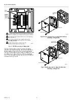
The Q7751A is a two-piece design allowing pre-wiring and
cable testing prior to installing the router. The front panel
includes a printed circuit board (PCB) with active electronics.
It also has a service switch and two service LEDs; a
combination power/wink LED, an activity LED and two
network connectors. See Fig. 1 for front panel view.
1
1
1
2
M16383
B
A
B A
LPR-10
UL UL
SERVICE
SWITCH
SERVICE
LEDs
CHANNEL A
CHANNEL B
POWER LED:
POWER ON: ILLUMINATED
CONTINUOUSLY
PACKET ACTIVITY LED ROUTER
TRANSFERRING PACKETS: FLASHING
OUTLET ACCESS JACKS; USE FOR ACCESS TO L
ON
W
ORKS
BUS.
ROUTER INTERFACE MODEL AND SOFTWARE REVISION NUMBERS.
PEEL-OFF CODE 39 FORMAT BAR CODE OF ROUTER INTERFACE
Neuron
®
CHIP ID NUMBER.
2
3
3
3
Fig. 1. Q7751A Router front plate.
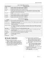
The router is installed in a Type 2 base plate. Wiring
connections are presented in Table 1. Specifications for the
router are shown in Table 2. Network and power are
connected to screw terminals located on a Type 2 base plate.
The router is plugged into the base plate. No wiring is ever
connected directly to the router. A writing space is provided
on the back of the base plate for recording the date of
installation and other important information. See Fig. 2 for
front view of base plate. See Fig. 3 for rear view of base
plate.
B
A
THREADED SCREW HOLES FOR ATTACHING ROUTER INTERFACE TO
BASE PLATE. USE 8-32, 3/8 IN. SCREW, Echelon 205-0130-01 OR EQUAL.
0.230 IN. HOLES FOR ATTACHING BASE PLATE TO ELECTRICAL BACK
BOX OR SUB-PANEL.
0.180 X 0.280 IN. HOLE FOR THE ATTACHING BASE PLATE TO
ELECTRICAL BACK BOX OR SUB-PANEL. USE 6-32, FLAT-HEAD,
3/8 IN. MINIMUM SCREW.
TEST
POINTS
INTERFACE
CONNECTOR
1
1
1
2
2
2
3
3
M16381
2
Fig. 2. Q7751A front view of base plate.
Q7751A Routers


