Honeywell Pressuretrol P7810C Скачать руководство пользователя страница 4

P7810C,D PRESSURETROL

®

 CONTROLLER

65-0235—1

4

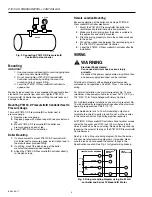
Fig. 2. Connecting P7810C,D Pressuretrol®

Controller to steam boiler.

Mounting

IMPORTANT

1. Use pipe compound sparingly to avoid clogging hole

in pipe or sensor element fitting.

2. Do not hand tighten P7810C,D Pressuretrol®

Controller connection by holding the case. Use
wrench on flats of sensor fitting.

3. Level the P7810C,D Pressuretrol® Controller for

appearance.

Make all pipe connections in accordance with applicable local
standards. Use parallel jaw wrench to tighten P7810C,D
Pressuretrol® Controller hexagonal fitting to avoid leaks and
damage to the case.

Mounting P7810C,D Pressuretrol® Controller Next to
Pressure Gauge

To mount P7810C,D Pressuretrol® Controller next to
pressure gauge:

1. Remove pressure gauge.
2. Replace gauge with siphon loop with tee connector on

top.

3. Mount P7810C,D Pressuretrol® Controller and

pressure gauge on end of tee.

4. Level P7810C,D after installation.

Boiler Mounting

1. If not convenient to mount P7810C,D Pressuretrol®

Controller next to pressure gauge, install siphon loop in
the manufacturer provided fitting.

2. If no fitting, mount the siphon loop at the boiler

manufacturer recommended location.

3. Attach the P7810C,D Pressuretrol® Controller directly

to the siphon loop.

Remote Location Mounting

Excessive vibration at the boiler can damage P7810C,D
Pressuretrol® Controller electronics.

1. Mount the P7810C,D Pressuretrol® Controller at a

remote location to eliminate vibration problems.

2. Make sure that all piping from the boiler is suitable to

the application and solidly mounted.

3. Pitch the piping properly to drain the condensate back

to the boiler.

4.  Mount the siphon loop between the remote piping and

the P7810C,D Pressuretrol® Controller.

5.  Level the P7810C,D Pressuretrol® Controller after the

installation.

WIRING

WARNING

Electrical Shock Hazard.
Can cause electrical shock, serious injury
or death.
Disconnect the power supply before wiring. More than
one power supply disconnect can be involved.

All wiring must comply with applicable electrical codes,
ordinances and regulations. Use NEC Class 1 line voltage
wiring.

For normal installation, use moisture-resistant No. 14 wire
(maximum size allowed) suitable for at least 167

°

F (75

°

C) or

194

°

F (90

°

C) for Flame Safeguard Primary Controls.

For high temperature installations, use moisture-resistant No.
14 wire selected for temperature ratings above the maximum
operating temperature of 158

°

F (70

°

C).

Use shielded wire for 4 to 20 mA modulating output and
terminate the shield to earth ground. Do not run these wires
in the same conduit as high voltage ignition leadwires.

All P7810C,D Pressuretrol® Controllers have terminal screws
under the top cover and 27/32 inch (22 mm) holes in both
sides for conduit, cables and wiring. Remove the top cover by
loosening the screw at the top of the P7810C,D Pressuretrol®
Controller case.

See Fig. 3 for a firing rate wiring diagram. Follow the burner
or boiler manufacturer wiring diagrams, if provided. Make
sure the loads do not exceed the contact ratings in the
Specifications section. See Fig. 4 for typical wiring hookup.

P7810C,D

GAUGE

BOILER

M11891

7800 SERIES PROGRAMMER

HIGH FIRE

COMMON

MODULATE

LOW FIRE

9K1

9K2

8K2

8K1

F

-

14

+

MODUTROL® 
MOTOR

P7810 
CONTROLLER

M17130

Fig. 3. Firing rate wiring diagram using 4 to 20 mA

controller and Series 70 Modutrol®  Motor.

Содержание Pressuretrol P7810C

Страница 1: ...th on off control function safety high limit and modulate and on off control and safety high limit functions Models available in 15 150 and 300 psi maximum setpoints LED indicators show power and call for heat function and lockout status Clear cover allows setpoint and differentials to be read but not adjusted without opening cover Manual reset possible without opening cover P7810C contains on off...

Страница 2: ... safety high limit P7810D Pressuretrol Controller with on off control and safety high limit Electrical Ratings Power Input 120 Vac 10 15 50 60 Hz Power Consumption Sensor Material 304 stainless steel Case Material Plastic Electrical Terminations Screw terminals Operating Temperature Range 32 F to 150 F 0 C to 65 C StorageTemperature 20 F to 150 F 29 C to 65 C Accuracy 4 0 percent full scale output...

Страница 3: ...t scale and corrosive vapors from attacking controller sensor element Mount the siphon loop in any position with a 0 to 90 pipe drain position Mount the P7810C D Pressuretrol Controller next to the pressure gauge in the manufacturer provided fitting on the boiler See Fig 2 Mount at a remote location to avoid excessive vibration or mount in a special mounting on a low water cutoff IMPORTANT 1 Locat...

Страница 4: ...ed 3 Pitch the piping properly to drain the condensate back to the boiler 4 Mount the siphon loop between the remote piping and the P7810C D Pressuretrol Controller 5 Level the P7810C D Pressuretrol Controller after the installation WIRING WARNING Electrical Shock Hazard Can cause electrical shock serious injury or death Disconnect the power supply before wiring More than one power supply disconne...

Страница 5: ...g rate to steam pressure changes b Steam pressure safety high limit control causes a safety shutdown and lockout when the steam pressure reaches a preset safety high limit setpoint Fig 5 Firing Rate Wiring Diagram using P7810C D Pressuretrol Controller and Series 90 Modutrol Motor with Manual Position Potentiometer and Auto Manual Switch M11892A 7800 SERIES PROGRAMMER MODUTROL MOTOR P7810 PRESSURE...

Страница 6: ...ses to or below the modulation setpoint the current is 20 mA The current remains constant at all pressures below the modulation setpoint The modulation range is an additive value to the modulation setpoint value When the pressure increases above the modulation setpoint the current decreases linearly until the modulation range point is reached The output current is 4 mA at and above this pressure S...

Страница 7: ...s carefully calibrated at the factory Test the P7810 Pressuretrol Controller as follows NOTE Make sure the P7810 is operating properly by checking the LED indicators If the P7810 LED indicate a lockout condition press the manual reset button NOTE This procedure simulates pressure changes using dial setpoint adjustments Make dial adjustments very slowly because of filtering delays within the P7810C...

Страница 8: ...ety lockout condition 3 Start the system and observe the operation through at least one complete cycle to make sure the P7810 functions properly as described in the Operation section TROUBLESHOOTING WARNING Electrical Shock Hazard Can cause electrical shock serious injury or death Line voltage is present at the P7810 and in all controller circuits Use extreme care while troubleshooting To determin...

Отзывы: