


16
NFW-50X Manual —
P/N LS10129-001NF-E:C 7/25/2018
Product Description
Optional Modules
Batteries
The NFW-50X cabinet provides space for two batteries (up to 18 Amp Hour). Batteries
larger than 18 Amp Hour require an external charger such as the CHG-75 or CHG-120
and a UL listed battery box such as the BB-26 or NFS-LBB. Batteries must be ordered
separately.
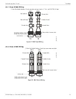
1.4.1 Intelligent Addressable Detectors
Intelligent, addressable detectors provide information to the control panel on an SLC Signaling Line Circuit (refer to the FireWar-
den/ONYX SLC Wiring Manuals for detailed information on device installation, wiring and operation). This allows the control panel to
continually process the information to determine the status (alarm, trouble, maintenance or normal) of each detector. Each detector
responds to an SLC address that is set in the detector head using built-in rotary decimal switches. The maximum address cannot exceed
address 50. Note that a blinking LED on an intelligent detector indicates communication between the detector and the control panel.
These devices can operate in CLIP mode (Classic Loop Interface Protocol) or FlashScan mode to provide a quicker response. Refer to
the FireWarden/ONYX SLC Wiring Manuals for a list of compatible addressable detectors or the Device Compatibility Document for
conventional detectors.
1.4.2 Intelligent Addressable Modules
Control Modules and Monitor Modules provide an interface between the control panel and conventional notification and initiating
devices. Each module can be set to respond to an address with built-in rotary switches. The maximum address cannot exceed address 50.
Note that a blinking LED on an addressable module indicates communication between the module and the control panel.
These devices can operate in CLIP mode (Classic Loop Interface Protocol) or FlashScan mode to provide a quicker response. Refer to
the
FireWarden/ONYX SLC Wiring Manuals
for a list of compatible addressable modules. Refer to the
Device Compatibility Document
for a list of approved conventional notification and initiating devices.
1.4.3 Addressable Device Accessories
End-of-Line Resistor Assembly
The End-of-Line resistors are included with each module. Refer to the specific module documentation for specific information.
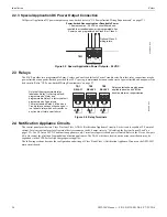
Power Supervision Relay
The UL listed End-of-Line power supervision relay is used to supervise the power to 4-wire smoke detectors and notification appliances.
EOL-C(R/W) Mounting Plate
The EOL-CR (red) and EOL-CW (white) are single End-of-Line resistor plates. An ELR, which is supplied with each module and fire
alarm control panel, is mounted to the EOL-C(R/W) plate. Resistors mounted to the plate can be used for the supervision of a monitor
and control module circuit.
1.5 Optional Modules
The NFW-50X main circuit board includes option module connectors for the following modules:
CELL-MOD/CELL-CAB-N
Optional GSM communicator card for central station reporting. It mounts in its own plastic or metal enclosure. Use of the CELL-
MOD/CELL-CAB-N requires the IPOTS-COM communicator. Connections are made from the CELL-MOD/CELL-CAB to the IPOTS-
COM.
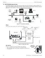
4XTM Transmitter Module
The 4XTM provides a supervised output for local energy municipal box transmitter, alarm and trouble reverse polarity. It includes a dis-
able switch and disable trouble LED. A jumper on the module is used to select an option which allows the reverse polarity circuit to open
with a system trouble condition if no alarm condition exists. The module plugs into connectors J5 and J6 which are located near the right
edge the main circuit board. When the 4XTM module is installed, Jumper JP3, on the main circuit board, must be cut to allow supervi-
sion of the module.
1.6 Accessories
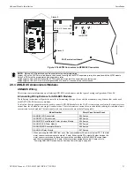
1.6.1 FS-Tools Programming Utility
The FS-Tools Programming Utility can be used to locally or remotely program the FACP from most Windows® compatible computers
(PC), running Windows 7 or newer, 32 or 64 bit. The FACP program files can also be created and stored on the PC for future download
to the control panel. FS-Tools can be downloaded from www.notifier.com. A standard USB cable with male-A to male-A connectors,
which must be purchased separately, is required for local connection of the PC to the USB port J20 on the FACP main circuit board.
Remote programming requires that the PC have a GSM or ethernet connection.
FS-Tools also provides the ability to create panel program files on a USB flash drive. The drive can then be plugged into USB port J20
on the FACP main circuit board.
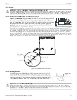
Battery Cable P/N 75287
9
2
0
0ba
tt.wmf
Содержание NOTIFIER NFW-50X
Страница 124: ...124 NFW 50X Manual P N LS10129 001NF E C 7 25 2018 Notes ...
Страница 154: ...154 NFW 50X Manual P N LS10129 001NF E C 7 25 2018 ...
Страница 156: ...Cut along dotted line ...
Страница 158: ...NOTIFIER 12 Clintonville Road Northford CT 06472 1610 USA 203 484 7161 www notifier com ...