IDR-M Mimic Installation & Commissioning Manual
Installation Guide
10
997-412-000-3, Issue 3
June 2005
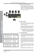
2.4.2 Typical Configuration - Relays
Typical interconnections when the output
channels are used to drive relays are given
below. The method of interconnecting IDR-MD
Driver boards via the SPI bus and identification
of the channels on the Mimic Termination
boards is identical to that given in
simplicity, only one Driver board and one Mimic
Termination board is shown in each example.
Jumper links must be set as described in
Relays can also be connected to the I/O lines
on the Mimic Driver Board - see


