IDR-2P, -2A & -6A Repeaters User Manual
Operation
32
997-411-000-9, Issue 9
March 2008
4.5.3.7 Disablement LED
The panel has a general Disablement LED
which is configured, by default, to illuminate
with the DELAY ACTIVE LED when a delay is
active.
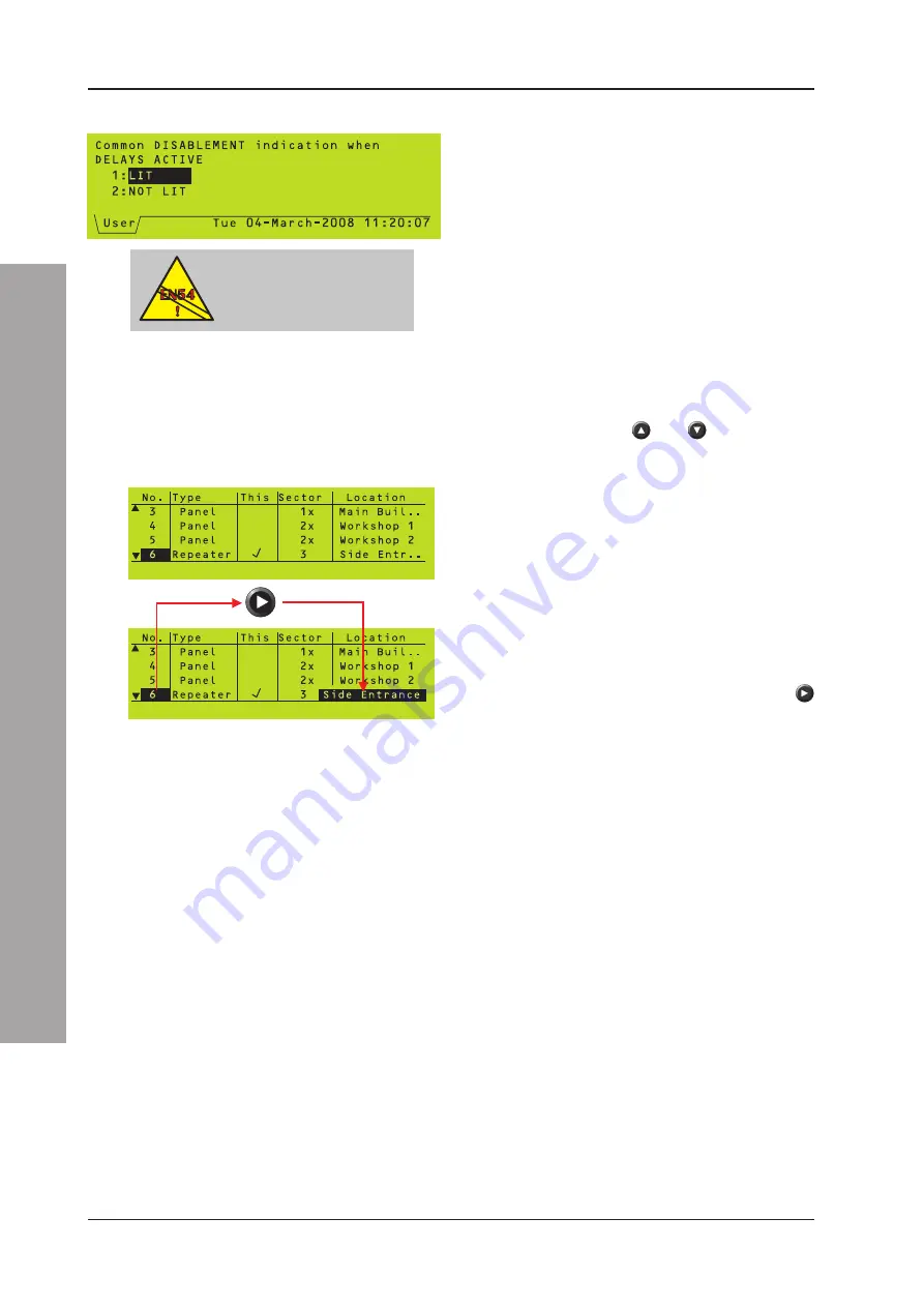
The repeater’s general Disablement LED can
be configured to not illuminate during active
delays. Access this option through the
configuration menu.
This is not EN54-2 compliant.
4.5.3.8 Network
This option provides a view of the panels and
repeaters on a Master/Slave or ID
2
net
Network. Use the
and
pushbuttons to
examine the nodes not currently displayed.
A tick symbol is displayed in the ‘This’ column
against the node assigned to this repeater.
Station text is displayed in the ‘Location’
column. This will be displayed when an event
such as an alarm or fault is indicated. Some
station descriptions may be too long to be
shown fully in the ‘Location’ column. In these
cases only the first part of the description is
displayed. To reveal all of the station text, select
the node address (node 6 is selected in the
example given here) and press the
pushbutton. The complete station text is then
revealed.
Network Filtering
Entries in the ‘Sector’ column indicate the
existence of network filtering. These will only
be relevant in a repeater connected via an
NGU and configured using the Windows
Configuration Tool v.2.14, or later.
A repeater will only display alarm, pre-alarm
and fault information related to its own sector.
All panel and repeater nodes assigned to other
sectors will be marked with an ‘x’ symbol (to
the right of the sector reference number)
indicating that they are not accessible to this
node.
EN54-2: 9.2
Delays are a disablement
and require the general
disablement indicator.


