


46
Notifier SLC Wiring Manual —
P/N 51253:U5 12/20/2017
Multiple Input/Output Modules
Wiring the Addressable Dual Monitor/Dual Relay Module
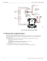
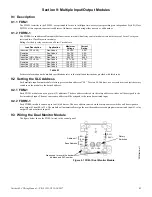
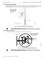
9.4 Wiring the Addressable Dual Monitor/Dual Relay Module
The figure below shows the FDRM-1 module wired to the control panel.
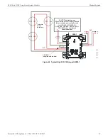
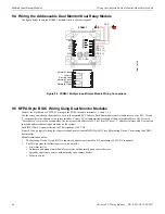
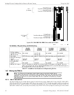
9.5 NFPA Style B IDC Wiring Using Dual Monitor Modules
Connect the FlashScan or CLIP SLC wiring to the FDM-1 module terminals 1 (–) and 2 (+).
Use the rotary switches on the module to set it to the required SLC address. Each dual module takes two addresses on the SLC. Circuit
‘L’ corresponds to the address set on rotary switches. Circuit ‘H’ will automatically respond at the next higher address. The Circuit L
“base address” is always an even number; the lowest possible address is 02. The Circuit H “base + 1” address is always odd. Use caution
to avoid duplicate addressing of modules on the system.
Each IDC (H & L) is power limited to 230 microamps @ 24 VDC.
Figure 9.3 shows typical wiring for a supervised and power-limited NFPA Style B (Class B) Initiating Device Circuit using the FDM-1
dual monitor.
Module installation notes:
1.
The Initiating Device Circuit (IDC) is supervised and current-limited to 210 microamps @ 24 VDC (nominal).
2.
The IDC provides the following services (do not mix):
• Fire alarm service
• Automatic and manual waterflow alarm service with normally open contact devices
• Sprinkler supervisory service with normally open contact devices
• Security service
SLC
fdrm-1.wmf
FDRM-1
IDC 1 (+)
IDC 1 (-)
IDC 2 (+)
IDC 2 (-)
NC
C
NO
NC
C
NO
Figure 9.2 FDRM-1 Multiple Input/Output Module Wiring Connections
Normally Closed
Common
Normally Open
Normally Closed
Common
Normally Open