background image

HPF902ULADA Distributed Power Module Installation Manual

4-5

Section 4
Installation

Before installing the HPF902ULADA, the AC input must first be wired into the building’s main electrical power 
through the TB1 terminals (see Figure 4-2). Shut off the electrical power to the HPF902ULADA, and then 
complete the general installation of the HPF902ULADA using the information in this section.

4.1

Mounting

Mount the HPF902ULADA in locations that meet the following temperature and humidity requirements. Do not 
expose the panel to conditions outside these ranges. For use in indoor, dry environments.

When mounting on interior walls, use appropriate screw anchors in plaster. When mounting on concrete, 
especially when moisture is expected, first attach a piece of 3/4-inch plywood to the concrete surface. Attach the 
HPF902ULADA to the plywood.

4.1.1

Preventing Water Damage

Water damage to the fire system can be caused by moisture entering the cabinet through the conduits. Conduits 
that are installed to enter the top of the cabinet are most likely to cause water problems. Installers should take 
reasonable precautions to prevent water from entering the cabinet. Water damage is not covered under warranty.

4.2

Wire Routing

To avoid induced noise (transfer of electrical energy from one wire to another), keep input wiring isolated from 
high current output and power-limited wiring. Induced noise can interfere with telephone communication or even 
cause false alarms. Avoid pulling a single multiconductor cable for the entire system. Instead, separate high 
current input/output from low current. Separate power-limited from non-power-limited wiring. 
Non-power-limited wiring must be enclosed in conduit.

Wiring within the cabinet should be routed around the perimeter of the cabinet. It should not cross the printed 
circuit board where it could induce noise into the sensitive microelectronics or pick up unwanted RF noise from 

Temperature

0

o

 C-49

o

 C (32

o

 F-120

o

 F)

Humidity

10%-93% at 30

o

 C (86

o

 F) noncondensing

Содержание HPF902ULADA

Страница 1: ...AC Expander INSTALLATION OPERATION MANUAL Honeywell Power Products 12 Clintonville Road Northford CT 06472 1653 USA Honeywell Power Products HPF902ULADA 9 Amp NAC Expander Document 151343 Rev N1 P N 151343 N1 ECN 17 0298 ...

Страница 2: ...necting devices This helps avoid potential damage Keep power limited wiring separate from non power limited wiring 120VAC 60Hz Input Battery Wires Minimum 25 spacing must be provided Use 75 C or higher rated UL insulated wire for connecting the unit to the electrical mains The useful life of the system s standby batteries and the electronic components may be adversely affected by extreme temperatu...

Страница 3: ... 6 4 4 Connecting the HPF902ULADA to a FACP 9 4 4 1 Common Trouble Relay 9 4 5 Notification Appliance Wiring 10 4 5 1 Class A Supervised Wiring 10 Class A Output Notification Circuits 10 Class A Supervised Input Circuits 10 4 5 2 Class B Supervised Wiring 11 Class B Output Notification Circuits 11 Class B Supervised Input Circuits 12 4 6 Ground Fault Detection Enable Disable Jumper 12 4 7 Battery ...

Страница 4: ...ECO Configurations 17 4 8 3 Setting the Loss of AC Delay 17 4 8 4 Setting the Auxiliary Output 17 Section 5 Sample Applications 18 5 1 Notification Power Applications 18 5 2 Non Resettable Power Application 20 5 3 Door Holder Application 21 Section 6 Troubleshooting 21 6 1 LEDs 21 6 2 Trouble Conditions 22 6 3 Earth Fault Resistance 23 6 4 Removing and Replacing the Control Panel 23 6 4 1 Removing...

Страница 5: ...the battery standby power When the auxiliary power is configured to switch off there is a 30 second delay before the auxiliary power is turned off after the AC power fails see Section 4 8 4 for details Form C Trouble Relay The HPF902ULADA includes a general trouble relay that will de energize for any trouble situation see Section 4 4 1 for details Earth Fault Detection The HPF902ULADA monitors for...

Страница 6: ...VAC 60 Hz 2A 2 Earth Ground 3 AC white neutral TB2 1 Auxiliary Power 27 4 VDC 3 0 amps 2 Auxiliary Power 3 Notification 4 Output 27 4 VDC 3 0 amps 4 Notification 4 Output Although each output 5 Notification 3 Output 27 4 VDC 3 0 amps is rated for 3 amps the 6 Notification 3 Output total current draw from 7 Notification 2 Output 27 4 VDC 3 0 amps the 4 outputs and the 8 Notification 2 Output auxili...

Страница 7: ...driven with forward polarity to activate the outputs the main control panel will not be able to sense trouble conditions through its notification appliance circuit connected to the HPF902ULADA input circuits Use the HPF902ULADA trouble relay when it is necessary to monitor trouble conditions and active alarm conditions at the same time Section 6 explains the significance of each trouble condition ...

Страница 8: ...Input 2 Outputs 3 and 4 Class B circuits 7 Input 1 Outputs 1 2 Class A circuit pair Input 2 Outputs 3 4 Class A circuit pair 8 Input 1 Outputs 1 2 Class A circuit pair Input 2 Outputs 3 and 4 Class B circuits 9 Input 1 Strobe Control All outputs Class A or Class B Input 2 Audio Control Faraday Sync Output 10 Input 1 Strobe Control All outputs Class A or Class B Input 2 Audio Control Gentex Sync Ou...

Страница 9: ...can be caused by moisture entering the cabinet through the conduits Conduits that are installed to enter the top of the cabinet are most likely to cause water problems Installers should take reasonable precautions to prevent water from entering the cabinet Water damage is not covered under warranty 4 2 Wire Routing To avoid induced noise transfer of electrical energy from one wire to another keep ...

Страница 10: ...t when the main panel supervises an ordinary notification appliance circuit 4 3 2 Current Drawn from Battery Batteries used with the HPF902ULADA must not exceed 35AH 33AH max for FM Factory Mutual Installations Batteries larger than 7 AH will not fit into the HPF902ULADA cabinet and must be housed in the Table 4 1 Alarm Current Drawn From Main Control Panel Panel Voltage Current Alarm Current for ...

Страница 11: ... 5 minutes of maximum alarm current 195 mA for 24 Hour Standby Current 39 mA for 60 Hours of Auxiliary Standby Current The above numbers were calculated assuming the use of 7 AH batteries at 100 of rated capacity The total current of the HPF902ULADA plus all items powered from it must not exceed 9 A when the panel is in alarm Use Table 4 2 to ensure that the current does not exceed 9 A and that th...

Страница 12: ...ication appliances Refer to device manual for current ratings Alarm mA 0 mA mA Alarm mA 0 mA mA Alarm mA 0 mA mA Alarm mA 0 mA mA C Notification Appliance Current 0 mA mA D Total current ratings of all devices in system line A line B line C mA mA E Total current ratings converted to amperes line D x 001 A A F Number of standby hours 24 or 60 for NFPA 72 Chapter 1 1 5 2 5 24 Hrs for NBC section 3 2...

Страница 13: ... for accessories Figure 4 2 The Model HPF902ULADA PC Board Layout Consult the installation manual for specific wiring information for the control panel being used 4 4 1 Common Trouble Relay The HPF902ULADA has a Form C trouble relay built into Terminals 11 13 The relay provides a normally open and a normally closed contact both of which are rated at 2 5A The trouble relay will deactivate under any...

Страница 14: ... using the outputs as Class A circuits loop the wiring back to the corresponding circuit pair For Class A wiring no external EOL is necessary since it is built into the HPF902ULADA board Class A Supervised Input Circuits The configuration shown in Figure 4 4 shows Class A supervised wiring from a fire alarm control panel to the HPF902ULADA board Pay close attention to the polarities when wiring a ...

Страница 15: ...ut wiring methods for proper supervision Refer to the Appendix for notification appliances approved for use with the HPF902ULADA Class B Output Notification Circuits Figure 4 5 shows four 1 5 A devices wired as Class B Place a 4 7k ohm EOL resistor provided at the end of each circuit to enable supervision when using all outputs as Class B notification appliance circuits The 4 7k EOLs must be wired...

Страница 16: ...ction feature on the HPF902ULADA may interfere with the ground fault detection feature of the main control panel in the system To disable the ground fault detection feature on the HPF902ULADA place the jumper block on J1 across Pins 1 and 2 see Figure 4 2 4 7 Battery Connection Use two 12 VDC 7 AH gel cell batteries inside the HPF902ULADA cabinet For batteries larger than 7 AH not to exceed 35 AH ...

Страница 17: ...s B Auxiliary power state Which NACs to operate as steady ANSI temporal or sync outputs Refer to Figure 4 2 for the location of the DIP switch on the HPF902ULADA board 4 8 1 Selecting the Standard Input Output Configurations Figure 4 7 and Figure 4 8 show the position of each switch for the non synchronized input and output configurations The position of Switches 4 and 5 does not affect the relati...

Страница 18: ...ith no synchronization DIP switches 6 and 7 must be turned On 4 8 1 1 Input Output Configurations That Select ANSI Temporal Coded Outputs The DIP switch settings marked with an asterisk in Figure 4 7 and Figure 4 8 are designed to produce ANSI temporal coded outputs from a constant input The figures shown below compare the output patterns of ...

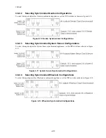
Страница 19: ...ections 4 8 2 1 4 8 2 2 or 4 8 2 3 4 8 2 1 Selecting Synchronized Faraday Configurations To select the input outputs for Faraday synchronized appliances set the DIP switches as shown in Figure 4 9 Figure 4 9 Faraday Synchronized Configurations Standard HPF902ULADA Input to Output Relationship Input Output Relationship for ANSI Temporal coded Options Important For all synchronization options input ...

Страница 20: ...lecting Synchronized System Sensor Configurations To select the input outputs for System Sensor synchronized appliances set the DIP switches as shown in Figure 4 11 Figure 4 11 System Sensor Synchronized Configurations 4 8 2 4 Selecting Synchronized Wheelock Configurations To select the input outputs for Wheelock synchronized appliances set the DIP switches as shown in Figure 4 12 Figure 4 12 Whee...

Страница 21: ...ly and the normal position for Switch 4 is OFF For testing the Low AC reporting you can temporarily turn Switch 4 ON without removing power Note Remember to turn the switch OFF when testing is complete Figure 4 14 Setting DIP Switch 4 4 8 4 Setting the Auxiliary Output Switch 5 on the DIP switch determines how the auxiliary power operates on the HPF902ULADA The HPF902ULADA checks Switch 5 only whe...

Страница 22: ...902ULADA configurations including daisy chaining 5 1 Notification Power Applications Figure 5 1 Input 1 Activates All Four Outputs Figure 5 2 Input 1 Activates NACs 1 and 2 Input 2 Activates NACs 3 and 4 HPF902ULADA Local Fire Alarm Control Panel Local Fire Alarm Control Panel HPF902ULADA ...

Страница 23: ...e used with one control unit they will not sync with each other Figure 5 3 One Control Activating Two HPF902ULADAs Figure 5 4 One Control Activating Three HPF902ULADAs in Series HPF902ULADA HPF902ULADA Local Fire Alarm Control Panel HPF902ULADA HPF902ULADA HPF902ULADA Local Fire Alarm Control Panel ...

Страница 24: ...dicated 3 A auxiliary power output that you can select as non resettable output is always on See Section 4 8 4 for setting the auxiliary power If you need more than 3 A wire the inputs as shown in Figure 5 6 Figure 5 6 Auxiliary Output Wiring for Non Resettable Power HPF902ULADA HPF902ULADA HPF902ULADA Local Fire Alarm Control Panel ...

Страница 25: ...control panel that is programmed to open under alarm conditions See Section 4 8 4 for selecting auxiliary power options Figure 5 7 Door Holder Wiring Example Section 6 Troubleshooting Light emitting diodes LEDs indicate fault conditions This section describes the LED states 6 1 LEDs The eight LEDs indicate a fault in one of the circuits either NACs 1 through 4 auxiliary power earth fault low AC or...

Страница 26: ... earth ground and one of the output circuit terminals is removed Power Limit At AUX Current draw at the auxiliary power terminals is exceeding 3 0 amps Power disconnects at the AUX terminal Input 1 and Input 2 supervision circuits open The yellow AUX LED lights The trouble relay is de energized The trouble restores when the overcurrent condition no longer exists When a circuit goes into a power li...

Страница 27: ... it is determined that the control panel needs to be repaired or replaced 6 4 1 Removing the Control Panel Follow these step to properly remove the control panel Table 6 1 Earth Fault Resistance Values by Terminal Function Terminal Number Terminal Label Value in kohms Auxiliary Devices 1 H5 AUX 0 2 H5 0 Notification Appliance Circuit 4 3 H4 OUT4 0 4 H4 0 Notification Appliance Circuit 3 5 H3 OUT3 ...

Страница 28: ... Panel Follow these steps to replace the control panel Note Use a grounding strap when working with static sensitive components 1 Align the control panel with the chassis mounting stand offs See Figure 6 1 2 Insert the four chassis mounting screws see Figure 6 1 Do not over tighten the chassis mounting screws 3 Insert the two heat sink screws see Figure 6 1 Do not over tighten the heat sink screws...

Страница 29: ...A 1 below lists notification appliances compatible with the HPF902ULADA Appliances which can be synchronized indicate the type of sync available in the columns marked Audio and or Visual Table A 1 Compatible Notification Appliances Manufacturer Model Audio Visual Type AMSECO SH24W 153075 x x Horn Strobe SAD24 153075 x Strobe SAD24 75110 x Strobe SL24W 75110 x Strobe SL24C 3075110 x Strobe SLB24 75...

Страница 30: ...e Horn 5336 x x Multi Tone Horn Strobe 5337 x x Multi Tone Horn Strobe 5338 x x Multi Tone Horn Strobe 5343 x x Single Tone Horn Strobe 5346 x x Electronic Horn with Strobe 5347 x x Electronic Horn with Strobe 5348 x x Single Tone Horn Strobe 5373 x x 8 Tone Horn Strobe 6321 x x Sync Mini Horn Strobe 6322 x x Mini Horn Sync Strobe 6380 x 8 Tone Electronic Signal Strobe 5376 x x 8 Tone Horn Strobe ...

Страница 31: ... Strobe 5522 x 4 Square Sync Strobe 6120 x Horn 6140 x Horn 6223 x Horn 6226 x x Horn Strobe 6227 x x Horn Strobe 6228 x x Horn Strobe 6243 x Electron Mechanical Horn 6244 x Electron Mechanical Horn 6245 x Electron Mechanical Horn 6246 x x Electron Mechanical Horn Strobe 6247 x x Electron Mechanical Horn Strobe 6248 x x Electron Mechanical Horn Strobe 6300 x Mini Horn 6301 x Mini Horn 6302 x Mini ...

Страница 32: ...be P241575 FC x x Horn Strobe P241575W FC x x Horn Strobe P241575F FC x x Horn Strobe P241575K FC x x Horn Strobe P2430 FC x x Horn Strobe P2430W FC x x Horn Strobe P2430K FC x x Horn Strobe P2475 FC x x Horn Strobe P2475W FC x x Horn Strobe P2475K FC x x Horn Strobe P24110 FC x x Horn Strobe P24110W FC x x Horn Strobe P24110K FC x x Horn Strobe S2430W FC x Strobe S2430K FC x Strobe S2475 FC x Str...

Страница 33: ...ndella Horn Strobe Ceiling Mount GCCR24 x Multi Candella Horn Strobe Ceiling Mount GCS24 x Multi Candella Strobe Ceiling Mount GCSR24 x Multi Candella Strobe Ceiling Mount GECR 24 x x Multi Candella Horn Strobe GES24 15 x Strobe GES24 30 x Strobe GES24 60 x Strobe GES24 75 x Strobe GES24 110 x Strobe GES24 15 75 x Strobe GES24 177 x Strobe GES3 24 x Multi Candella Strobe GESR 24 x Multi Candella S...

Страница 34: ...e Horn Strobe P2RH x x 2 Wire Horn Strobe High Candela P2RH P x x 2 Wire Horn Strobe High Candela PC2RH x x 2 Wire Horn Strobe High Candela PC2RH P x x 2 Wire Horn Strobe High Candela P2W x x 2 Wire Horn Strobe P2W P x x 2 Wire Horn Strobe PC2W x x 2 Wire Horn Strobe PC2W P x x 2 Wire Horn Strobe P2WH x x 2 Wire Horn Strobe High Candela P2WH P x x 2 Wire Horn Strobe High Candela PC2WH x x 2 Wire H...

Страница 35: ... PC2WL x x Horn Strobe 2W WHT Ceil 4x4 P2GRL x x Horn Strobe 2W Red Wall 2x4 P2GWL x x Horn Strobe 2W WHT Wall 2x4 P4RL x x Horn Strobe 4W Red Wall 4X4 P4WL x x Horn Strobe 4W WHT Wall 4X4 PC4RL x x Horn Strobe 4W Red Ceil 4X4 PC4WL x x Horn Strobe 4W WHT Ceil 4X4 SR x Strobe SR P x Strobe SCR x Strobe SCR P x Strobe SRH x Strobe High Candela SRH P x Strobe High Candela SCRH x Strobe High Candela ...

Страница 36: ... Horn AH 12WP x Horn Weatherproof AH 24WP x Horn Weatherproof AMT 241575W x x Multi Tone Horn Strobe AMT 24MCW x Mutli Tone Horn Strobe AMT 241575W NYC x x Multi Tone Horn Strobe AMT 12 24 x Multi tone Horn AMT 12 24 NYC x Multi tone Horn AS 121575W x Horn Strobe NH 12 24 x x Horn AS 241575W x x Horn Strobe AS 24MCC x x Horn Strobe AS 24MCCH x x Horn Strobe AS 24MCW x x Horn Strobe AS 24MCWH x x H...

Страница 37: ... x Multitone Horn Strobe MTWPG 2475W x x Multitone Horn Strobe MTWPR 2475W x x Multitone Horn Strobe MTWPA 24MCCH x x Multitone Horn Strobe ZNH x Horn NS 121575W x x Horn Strobe NS 241575W x x Horn Strobe NS 24MCW x x Horn Strobe NS 24MCC x x Horn Strobe NS 24MCCH x x Horn Strobe ZNS MCW x x Horn Strobe ZNS MCWH x x Horn Strobe ZNS 24MCC x x Horn Strobe ZNS 24MCCH x x Horn Strobe RSS 121575W x Str...

Страница 38: ...Strobe Weatherproof RSSWPR 24MCCH x Strobe Weatherproof RSSWP 2475W x Strobe Weatherproof RSSWP 2475C x Strobe Weatherproof RSSWP 24MCWH x Strobe Weatherproof ZRS MCWH x Strobe ZRS 24MCC x Strobe ZRS 24MCCH x Strobe MB G6 24 x Motor Bell MB G10 24 x Motor Bell MB G6 12 x Motor Bell MB G10 12 x Motor Bell MIZ 24 R x Mini Horn MT 12 24 R x x Multitone Horn MT4 12 2z x x Multitone Horn ZRS MCW x Stro...

Страница 39: ......

Страница 40: ...12 Clintonville Rd Northford CT 06472 1653 Phone 203 484 7161 Honeywell Power Products P N 151343 ...

Отзывы: