background image


Connected Industrial 


HON 512 
gas pressure regulator 
with HON 650 pilot 

User and maintenance manual 
Spare parts 


Содержание HON 512

Страница 1: ...Connected Industrial HON 512 gas pressure regulator with HON 650 pilot User and maintenance manual Spare parts ...

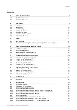
Страница 2: ...stalling the gas pressure regulator 46 5 3 Installing the device connections 48 5 4 Checking the system for leaks 50 5 5 Starting up the gas pressure regulator 53 6 Adjusting the settings of the device 55 6 1 Adjusting the loading pressure 56 6 2 Adjusting the control stage setpoint 57 6 3 Adjusting the amplifying valve 59 7 Malfunctions 61 7 1 Malfunctions 62 8 Maintenance 65 8 1 Maintenance sche...

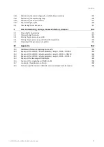
Страница 3: ...tor 149 9 4 Putting the gas pressure regulator back into operation 150 9 5 Disposing of the gas pressure regulator 151 10 Appendix 152 10 1 Additional information regarding spare parts 153 10 2 Spare parts for HON 512 actuator assembly design 1 DN 25 DN 100 155 10 3 Spare parts for HON 512 actuator assembly design 2 DN 150 DN 250 162 10 4 Spare parts for HON 512 actuator assembly design 3 DN 25 DN...

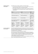
Страница 4: ...General considerations HON 512 with HON 650 pilot user manual 4 1 General considerations Topic Page About this user manual 5 About the safety notices 7 Contents ...

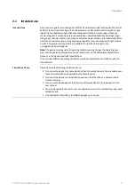
Страница 5: ...ber of different sizes For this reason we are unable to guarantee that illustrations in this user manual coincide with the dimensions of your product In these cases the illustrations should be viewed as a concept sketch Failing to observe the information provided in this document may lead to injuries including death and material damages To ensure the safety any persons handling the product must ha...

Страница 6: ... mail gas ks honeywell com Website www honeywellprocess com Printed in Germany The manufacturer is not liable for damages and malfunctions arising from non observance of this user manual and the other applicable documents The written approval from Honeywell Gas Technologies GmbH Kassel is required for any modifications and additions to the product Any violation will void the legal liability for co...

Страница 7: ...chapter Instruction related safety notices Safety notices containing specific instructions relating to the entire manual or a group of manuals Step related safety notices Safety notices containing specific instructions relating only to the step DANGER WARNING CAUTION Additional safety notice Instruction to observe certain safety notices with reference to a location in the document where safety not...

Страница 8: ...h HON 650 pilot user manual 8 2 Description Topic Page Intended use 9 Device models 10 Labels Markings 12 Identifying the device 13 Layout and operation 15 Assemblies and their function 17 Technical specifications 22 Contents ...

Страница 9: ...ustrial gases Note The gas pressure regulator s operating limits concerning the gas the operating pres sure and the operating temperature can be found either on the nameplates affixed to the device or in the device s technical specifications The use under different operating conditions must be coordinated in consultation with the manufacturer Please observe the following limitations of use Do not ...

Страница 10: ...out protection against overpressure for setpoint ranges Wd of 10 to 40 bar HON 915 vent valve Electrical remote setpoint adjustment for control stage and or load limiting stage The standard HON 650 pilot version features two stages i e it includes both a load limiting stage and a control stage The manufacturer uses designation HON 650 1 for the single stage pilot version featuring a control stage ...

Страница 11: ...noise reduction Without in tegrated noise reduction Nominal outlet size Nominal inlet size Nominal outlet size Nominal inlet size Nominal outlet size Nominal inlet size Nominal outlet size Nominal inlet size Nominal outlet size Nominal inlet size The technical specifications see page 22 as well as the spare parts lists and spare parts drawings in the appendix see page 152 describe all the gas pres...

Страница 12: ...ged and missing labels The following labels markings can be found on the actuator assembly s casing Figure No Meaning 1 Body part number 2 Body material 3 Material grade 4 Body pressure testing specifications 5 Body pressure testing specifications 6 Manufacturer s logo Batch number Foundry marking Radiographic film number 7 Arrow indicating the direction of flow 8 Manufacturer plant number 9 Flang...

Страница 13: ...he locations shown below Figure No Description 1 Actuator assembly nameplate 2 Pilot nameplate The details on the type plate have the following meaning Figure No Meaning 1 Name of the device 2 Pressure rating Flange standard 3 Inlet outlet nominal size 4 CE specifications 5 Differential pressure max 6 Max permissible pressure 7 Valve seat diameter 8 Serial number 9 Temperature class 10 Inlet press...

Страница 14: ...manual 14 The details on the type plate have the following meaning Figure No Meaning 1 Name of the device 2 Serial number 3 Maximum allowable pressure 4 Controlled variable 5 Specific set range 6 Setpoint Interpreting the type plate of the pilot ...

Страница 15: ...assembly For nominal inlet sizes of DN 25 to DN 100 3 piece body with without expander for pressure ratings PN 25 PN 40 ANSI Class 300 ANSI Class 600 2 piece body without expander for pressure ratings PN 16 ANSI Class 150 For nominal inlet sizes of DN 150 to DN 300 2 piece body without expander for all pressure ratings 2 piece body with expander for pres sure ratings PN 25 PN 40 ANSI Class 300 ANS...

Страница 16: ...conveying sleeve 5 will unblock the gas flow at the valve disc 2 The actuator assembly s degree of opening will be dynamically regulated as a result of the changing motorization pressure on one side of the diaphragm unit and the changing outlet pressure on the other side of the diaphragm unit This keeps the outlet pressure on the gas outlet side 3 constant within specific limits The limits within ...

Страница 17: ...uster 7 Load limiting stage spring adjuster not part of single stage pilot version 8 HON 905 fine mesh filter 9 Inlet pressure gauge The HON 650 pilot features the following connections Figure No Meaning 1 Port for inlet pressure line 2 Inlet pressure fitting 3 Inlet pressure gauge fitting 4 Loading pressure gauge fitting not part of single stage pilot version 5 Port for outlet pressure sensing li...

Страница 18: ... the gas pressure and on the set setpoint the position of the double dia phragm system position inside the control stage will vary slightly This position change will result in a small large gap between the stationary nozzle and the deflector plate being cleared inside the double diaphragm system At the nozzle there will be gas with the loading pressure generated in the load limiting stage in the c...

Страница 19: ...Visual position indicator for opening state 4 Slinging point eye bolt 5 Gas outlet expansion consisting of noise reducing outlet duct optional 6 Electrical displacement transducer op tional opening state monitoring 7 Diaphragm unit inside The HON 512 actuator assembly features the following connections Figure No Meaning 1 Gas regulating line gas inlet fitting 2 Port for inlet pressure line 3 Outle...

Страница 20: ...hen this unit is moved to its right hand end position in the gas direction of flow the sleeve that conveys gas will slide onto the valve disc Accordingly the actuator assembly will be closed and the flow of gas will be suppressed In the left hand end position there will be the biggest possible gap between the sleeve and the valve disc In this state the actuator assembly will be completely open and...

Страница 21: ...with this pressure acting as a force component on the dia phragm unit In the body chamber upstream of the diaphragm unit the force of the compression spring s and the force of the gas pressure there both act on the diaphragm unit In order for the actuator assembly to be opened or kept open the force exerted by the motorization pressure must be greater than the forces opposing it The visual positio...

Страница 22: ...Actuator assembly and pilot Diaphragms NBR Upon request FKM FPM Actuator assembly and pilot Gaskets NBR Upon request FKM FPM The KG values apply to natural gas with a density of ρn 0 83 kg m Nominal size DN Nominal size DN Inlet Outlet KG coefficient m h Inlet Outlet KG coefficient m h 25 25 550 150 150 19800 100 490 300 14630 150 490 400 16830 50 50 2200 200 200 37400 150 1920 400 25850 200 1980 ...

Страница 23: ... 0 6 21 0 8 4 28 61 7 50 50 270 10 6 M16 20 0 8 25 1 8 61 134 5 80 80 310 12 2 M16 20 0 8 25 1 8 63 138 9 100 100 370 14 6 M16 26 1 0 32 1 3 12 Approx 120 264 6 Nominal size DN PN 25 PN 40 Inlet Outlet D mm in E mm in L mm in A B mm in C mm in N Qty Weight kg lbs 25 25 200 7 9 M12 16 0 6 21 0 8 4 35 77 2 100 75 3 0 180 7 1 360 14 2 M12 16 0 6 21 0 8 4 80 176 4 150 84 3 3 180 7 1 360 14 2 M12 16 0 ...

Страница 24: ...7 1 359 14 1 M16 20 0 8 25 1 0 4 80 176 4 150 84 3 3 180 7 1 359 14 1 M16 20 0 8 25 1 0 4 90 198 4 50 50 267 10 5 M16 20 0 8 25 1 0 8 70 154 3 150 84 3 3 220 8 7 421 16 6 M16 20 0 8 25 1 0 8 130 286 6 200 92 3 6 220 8 7 421 16 6 M16 20 0 8 25 1 0 8 150 330 7 80 80 318 12 5 M20 26 1 0 32 1 3 8 120 264 6 250 100 3 9 260 10 2 516 20 3 M20 26 1 0 32 1 3 8 300 661 4 100 100 368 14 5 M20 26 1 0 32 1 3 8...

Страница 25: ... 300 11 8 555 21 9 M20 26 1 0 32 1 3 8 425 937 0 Nominal size DN ANSI 600 RF RTJ Inlet Outlet D mm in E mm in L mm in A B mm in C mm in N Qty Weight kg lbs 25 25 210 8 3 M16 20 0 8 25 1 0 4 35 77 2 100 75 3 0 180 7 1 365 14 4 M16 20 0 8 25 1 0 4 80 176 4 150 84 3 3 180 7 1 365 14 4 M16 20 0 8 25 1 0 4 90 198 4 50 50 286 11 3 M16 20 0 8 25 1 0 8 70 154 3 150 84 3 3 220 8 7 430 16 9 M16 20 0 8 25 1 ...

Страница 26: ... 300 103 4 1 350 13 8 550 21 7 580 1279 550 21 7 580 1279 400 113 4 4 350 13 8 550 21 7 770 1698 550 21 7 770 1698 200 200 610 24 0 850 1874 610 24 0 850 1874 400 113 4 4 380 15 0 650 25 6 1000 2205 650 25 6 1000 2205 500 137 5 4 380 15 0 650 25 6 1100 2425 650 25 6 1100 2425 250 250 630 24 8 980 2161 630 24 8 980 2161 400 113 4 4 420 16 5 660 26 0 1100 2425 660 26 0 1100 2425 500 137 5 4 420 16 5...

Страница 27: ...610 24 0 850 1874 610 24 0 850 1874 400 113 4 4 380 15 0 650 25 6 1000 2205 650 25 6 1000 2205 500 137 5 4 380 15 0 650 25 6 1100 2425 650 25 6 1100 2425 250 250 630 24 8 980 2161 630 24 8 980 2161 400 113 4 4 420 16 5 660 26 0 1100 2425 660 26 0 1100 2425 500 137 5 4 420 16 5 660 26 0 1200 2646 660 26 0 1200 2646 250 250 752 29 6 Upon request 752 29 6 Upon request 500 137 5 4 420 16 5 752 29 6 Up...

Страница 28: ...int range Wd 0 3 1 bar Without pressure gauge for outlet pressure The figure below shows the dimensions for the pilot with the control stages for setpoint ranges Wd 0 5 90 bar Without pressure gauge for outlet pressure With outlet pressure gauge pd 1 20 bar With outlet pressure gauge pd 10 90 bar Metric system Pilot dimensions and weights ...

Страница 29: ...ht lbs A in B in C in D in E in F in 0 3 1 Approx 13 5 7 7 1 6 1 2 4 0 1 0 5 0 0 5 40 Approx 11 0 7 7 1 6 1 1 4 0 1 0 5 0 10 90 Approx 14 5 12 4 1 6 1 1 4 0 1 0 5 0 Outlet pressure area pd range bar G in H in I in J in K in L in M in N in O in 0 3 1 8 5 3 7 2 6 2 2 3 5 9 1 5 2 3 5 0 9 0 5 40 7 5 1 4 2 6 2 2 2 7 8 2 6 1 10 90 7 5 1 4 2 6 1 3 3 0 8 0 5 2 Specific set range Wds Pilot spring No Color ...

Страница 30: ...following accuracy class and look up pressure class apply to gas pressure regulators consisting of an HON 512 actuator assembly combined with an HON 650 pilot Setpoint range Wd bar Accuracy class AC Look up pressure class SG 0 3 0 5 10 30 0 5 1 10 20 1 2 5 2 5 10 2 5 5 0 1 10 5 0 1 5 The properties of the gas conveyed through the gas pressure regulator consisting of an HON 512 actuator assembly co...

Страница 31: ...Safety HON 512 with HON 650 pilot user manual 31 3 Safety Topic Page Basic safety rules 32 Requirements concerning the workforce personal protective gear workplaces 34 Contents ...

Страница 32: ...procedures outlined in this user manual and on the device In particu lar wear the mandatory personal protective gear Only stay at the specified work places Do not modify the device in any way e g by removing parts or adding unapproved parts In particular you have no permission to modify or disable any safety contrivanc es Adhere to the device maintenance intervals specified in this user manual Whe...

Страница 33: ... built such that the employees can work with it without being at risk In spite of all the precautions accidents can happen under unfavorable circumstances Always consult the directives of your company concerning the protection of the workforce Conduct in the event of accidents ...

Страница 34: ... Knowledge of the relevant standards and regulations Ability to identify and avoid dangers autonomously Knowledge with securing hauling distances Knowledge with the use of hoisting equipment Transportation personnel Intra company transport Professional training and experience with the transport using stackers etc Mechanical fitter Mechanical installation Professional training and experience operat...

Страница 35: ...ng and experience with the disposal of pressure equipment and systems Knowledge of the relevant standards and regulations Ability to identify and avoid dangers autonomously Any persons handling the device must be equipped with the following personal protective gear Task Required personal protective gear Start up operation including partial cleaning maintenance search and remedy of errors Industria...

Страница 36: ... the device in a pipe HON 512 with HON 650 pilot user manual 36 4 Basics for installing the device in a pipe Topic Page Installation examples 37 Meter run characteristics 40 Operating and measuring impulse lines 42 Contents ...

Страница 37: ...th expander without noise reduction element downstream of the gas pressure regu lator Configuration Indirect acting gas pressure regulator pilot operated With expander without noise reduction element downstream of the gas pressure regu lator Outlet pressure gauge with protection against overpressure Gas pressure regulating line example 1 Gas pressure regulating line example 2 ...

Страница 38: ...ct acting slam shut device pilot operated two With expander without noise reduction element downstream of the gas pressure regu lator The numbers have the following meaning No Meaning 1 Safety Shut Off Valve 2 Gas pressure regulator 3 Pilot 4 Safety relief valve 5 Outlet stop valve armature 6 Sensing point for connection lines gray area 7 Return line 8 Bleed line 9 Gas pressure regulator measuring...

Страница 39: ...0 pilot user manual 39 No Meaning 11 Vent line 12 Relief line 13 Blowdown line Following is the meaning of the acronyms Acr Meaning DN Nominal size of pipe LuR Undisturbed length of pipe Shut off device with undisturbed flow pattern ball valve can be incorporated ...

Страница 40: ...t the sensing point On a case by case basis and following consultation with the manufacturer even lower flow rates may be al lowed Depending on the specific system design the LuR lengths of the undisturbed pipes upstream of the sensing point must be 2 5 to 5 x DN of the pipe with the specifics depending on the gas pressure regulator model and whether or not there is a pipe expander downstream If a...

Страница 41: ...ng elements in terms of measuring impulse line connections For gas meters turbine gas meters including quantometers ultrasonic gas meters and vortex flow meters but NOT rotary piston gas meters there are no restrictions in terms of measuring impulse line configurations as these meters are not considered to be flow disturbing within this context The following applies to rotary piston gas meters Min...

Страница 42: ...ragm to the atmosphere If the measuring unit becomes damaged e g diaphragm rupture it can start conveying gas Under certain operating conditions and following consultation with the manufacturer vent lines can be omitted if vent valves HON 915 or safety diaphragm configurations can be used instead Blowdown line The blowdown line in a safety relief valve is used to divert gas leaking gas for example...

Страница 43: ...er manual 43 5 Transport installation and start up Topic Page Transporting the gas pressure regulator 44 Installing the gas pressure regulator 46 Installing the device connections 48 Checking the system for leaks 50 Starting up the gas pressure regulator 53 Contents ...

Страница 44: ...sure that no person is within the danger zone A mobile workshop crane is suitable for use as hoisting equipment A pallet jack or forklift is also suitable for intraplant transportation The following are adequate for use as slings Ropes Belts Chains The hoisting equipment and slings must meet the following criteria The load capacity must be sufficient for the gas pressure regulator s weight The hoi...

Страница 45: ...ransport panels 1 on the gas pressure regulator during transport 2 Hook the slings 1 into all the eye bolts 2 intended to function as attachment points for transportation 3 Slowly and carefully lift the device 4 Slowly and carefully transport the device to the location where it will be installed Transporting the gas pressure regulator ...

Страница 46: ...r size and thread type are based on the flange design and size Adapter optional Length as per Technical specifications see page 22 version as per gas regulating line Assess the installation situation The numbers have the following meaning Figure No Meaning 1 Gas inlet side gas regulating line 2 Gas regulating line flange gasket adapter 3 Adapter optional 4 Adapter flange gasket gas regulating line...

Страница 47: ... components can be installed in the gas regulating line without any stress and that the gas regulating line s weight will be supported as well 6 Install the flange gaskets 7 Insert the screws 8 Tighten the screws on the flanges in a criss cross sequence When doing so make sure to observe the torques specified by the flange gaskets manufacturer Conduct a final inspection to check whether the follow...

Страница 48: ...e measuring impulse line Measuring impulse line needs to be installed Prepare the following materials Pipes connecting pieces and fittings as per the specifications in the Technical specifica tions see page 22 Shut off devices for the operating and measuring impulse lines as well as other acces sories as required The installation of the operating and measuring impulse lines depends on the local co...

Страница 49: ... instructions Conduct a final inspection to check whether the following criteria are met All threaded joints on the connection lines have been checked to ensure that they have a secure fit All electrical connections are securely fastened clamped and fused If then at least one criterion is not met you should correct the error before proceeding with the next task all criteria are met you may proceed...

Страница 50: ...jury posed by pressurized components moving in an uncontrolled manner when handled improperly If not handled properly or in the event of a defect gas can escape from pressurized compo nents under high pressure and cause serious injuries and even death Before you start work ing on these components Close all connections leading to the gas carrying line Establish a depressurized status Residual amoun...

Страница 51: ...e gauge 9 Outlet stop valve armature By default the gas pressure regulators supplied by the manufacturer are configured at the factory as required for the operating specifications provided by the customer These specifica tions will be found in the inspection certificate associated with the gas pressure regulator Make sure that the following requirements are met The specifications for the gas press...

Страница 52: ...he gas pressure regulator is not reached or maintained in the outlet chamber Adjust the setpoints for the load limiting stage and control stage on the pilot as specified in Adjusting the settings of the device see page 55 Proceed with step 4 Step Description 5 Apply the test medium to all detachable pipe joints 6 Observe the test medium on all detachable pipe joints for several minutes If then no ...

Страница 53: ... the following requirements are met The system has been checked is fully functional and has no leaks The inlet and outlet shut off devices for the gas regulating line section are closed The shut off devices for the blowdown lines are closed The inlet pressure is present upstream of the inlet shut off device Details about the operating pressure can be found in the technical specifications see page ...

Страница 54: ...the visual position indicator The actuator assembly will close You can observe this by monitoring the visual position indicator Result The reseating pressure set with the pilot will be reached in the outlet chamber The outlet pressure will be present inside the outlet chamber upstream of the outlet shut off device 3 Slowly open the outlet shut off device 3 4 Monitor the gas pressure regulator s co...

Страница 55: ... of the device HON 512 with HON 650 pilot user manual 55 6 Adjusting the settings of the device Topic Page Adjusting the loading pressure 56 Adjusting the control stage setpoint 57 Adjusting the amplifying valve 59 Contents ...

Страница 56: ...g pressure please check the load limiting stage pressure gauge reading Proceed as follows Figure Step Description 1 Unscrew the lock nut 1 on the set screw 2 located on the underside of the pilot s load limiting stage 2 Turn the set screw until the load limiting stage pressure gauge shows the setpoint you want Counterclockwise to loosen the pilot spring or Clockwise to tighten the pilot spring 3 T...

Страница 57: ...or outlet pressure pd The shut off devices for the blowdown lines are closed The inlet pressure is present upstream of the inlet shut off device Proceed as follows Figure Step Description 1 Unscrew the lock nut 1 on the set screw 2 located on the underside of the pilot s control stage 2 Loosen the set screw 2 until the tension in the pilot spring has been relieved 3 Open the inlet shut off device ...

Страница 58: ...ual 58 Figure Step Description 6 Wait a few minutes and check the reading for outlet pressure pd in the outlet cham ber 7 If necessary keep adjusting the set screw setting until you get the right outlet pressure pd 8 Tighten the lock nut 1 to secure the set screw 2 setting ...

Страница 59: ...You want to slow down the actuator assembly s response Carry out step 2a and then continue to step 3 You want to speed up the actuator assembly s response e g in the case that there are oscilla tions Carry out step 2b and then continue to step 3 Figure Step Description 2a Use a flat blade screwdriver to screw the spindle 1 deeper into the sleeve turn by turn while monitoring the actuator assem bly...

Страница 60: ...Adjusting the settings of the device HON 512 with HON 650 pilot user manual 60 Figure Step Description 3 Put the amplifying valve cap back in place ...

Страница 61: ...Malfunctions HON 512 with HON 650 pilot user manual 61 7 Malfunctions Topic Page Malfunctions 62 Contents ...

Страница 62: ... them Malfunction Possible causes Correction No flow Pilot Not connected correctly Check the pilot s operation and connections and make any adjust ments required Pilot Not enough amplification Adjust the amplifying valve as specified in Adjusting the amplify ing valve see page 59 Pilot The filter is dirty Clean the filter insert as specified in the Maintaining the filter section in Maintaining the...

Страница 63: ...r assembly will not close Pilot Faulty amplifying valve Perform maintenance on the pilot as specified in Maintaining the pilot see page 102 Pilot Motorization pressure too high Check the pilot spring to make sure it is set correctly and is not dam aged as specified in Maintaining the pilot see page 102 Adjust the control stage s setpoint as specified in Adjusting the control stage setpoint see pag...

Страница 64: ...tenance see page 65 section Unstable outlet pressure behavior oscillations Pilot Excessive amplification Adjust the amplifying valve as specified in Adjusting the amplify ing valve see page 59 The actuator assembly is operating in the reseating pressure range Check the design specifications contact the manufacturer if neces sary The visual position indica tor is not working Position indicator The ...

Страница 65: ...2 with HON 650 pilot user manual 65 8 Maintenance Topic Page Maintenance schedule 66 Preparing for the maintenance 67 Maintaining the actuator assembly 69 Maintaining the pilot 102 Completing the maintenance 141 Contents ...

Страница 66: ...e intervals It is recommended to use maintenance intervals conforming to the specifications in DVGW Code of Practice G 495 In addition the need for maintenance must be determined and documented on the basis of operational requirements and experience Maintenance must be carried out in compliance with all federal and state laws and regula tions as well as with the local rules and regulations set for...

Страница 67: ...ilot Compression spring s Pressure gauge s Filter insert 2 Preparing special tools In addition to standard tools have the special tools required for your specific gas pressure regulator model ready to go before maintenance Please refer to the Special tools section in Lubricants threadlockers and tools see page 202 You will also need a ballpoint pen or felt tip marker to perform maintenance on the ...

Страница 68: ...Maintenance HON 512 with HON 650 pilot user manual 68 facturer without fail before starting any work on the device ...

Страница 69: ...ual 69 8 3 Maintaining the actuator assembly Topic Page Maintaining the actuator assembly Design 1 example with expander 70 Maintaining the actuator assembly Design 2 example without expander 83 Maintaining the actuator assembly Design 3 93 Contents ...

Страница 70: ...torso area Make sure to always have enough people lifting heavy device components guideline using metric units 15 max 55 kg guideline using imperial units 30 max 120 lbs de pending on age and gender Comply with all the occupational health and safety regula tions and instructions that apply at the installation location Use suitable hoisting equipment and slings in order to handle heavy device compo...

Страница 71: ...6 15 11 15 11 Maintaining the inlet body 24 100 74 100 74 100 74 250 185 250 185 250 185 250 185 250 185 500 369 500 369 Assembling the actuator assembly 1 30 22 30 22 30 22 100 74 100 74 100 74 100 74 100 74 250 185 250 185 For purposes of clarity the wire springs are shown as hatched areas in the diagrams When the relief housing is filled with wire springs the wire springs must protrude upwards ...

Страница 72: ...let body 3 from the inlet body 1 downwards During lifting make sure not to damage the position indicator 2 Set down the outlet body 3 on a separate working surface as shown and secure the assembly s position taking its high center of gravity into ac count Proceed as follows Figure Step Description 1 Remove the visual position indicator s retaining ring 1 2 Remove the cover ring 1 and the sight gla...

Страница 73: ...ssure on the body Slowly unscrew the screws until the compression spring s pressure is relieved 2 Turn the connection flange 180 Remove the two support rings 1 Replace the O ring 2 with a new greased O ring Insert the support rings back in place as shown in the diagram on the top left In the case of nominal sizes DN 50 the support rings will not be split in a helical pattern 3 Check the guide ring...

Страница 74: ...guide ring 2 for damage Replace it if necessary Fill the chamber with grease for valve sleeves as per the lubricant table via the guide ring 8 Check the compression spring for damage Replace it if necessary Place the compression spring back in the inlet body 9 Take the diaphragm unit Use the sleeve 3 as a reference The figure on the left shows the sealing edge 1 facing upwards This sealing edge fe...

Страница 75: ... Slide the diaphragm plate 1 downwards and remove the sleeve 2 Use a rubber mallet if necessary 14 Check the sleeve s sealing edge for notch es damage If necessary replace the sleeve with a new one See step 9 for reference In versions with reverse flow protection the outer upper edge will be the sealing edge 15 Replace the O ring 2 in the diaphragm plate with a new greased O ring and clean the dia...

Страница 76: ...18 Place the new diaphragm 1 and the mounting plate 2 on the diaphragm plate as shown in the figure to the left Tighten the screws 3 in a criss cross sequence Refer to the additional tightening torque information at the beginning of this topic 19 Pull the diaphragm all the way down over the diaphragm plate Fold the diaphragm body back to half its height 20 Place the diaphragm unit back in the inle...

Страница 77: ...t sizes of DN25 DN100 protect the valve sleeve with an assembly disc as per the list of special tools 23 Align the connection flange on the body in such a way that the eye bolt 1 is aligned with the two holes 2 3 24 Tighten the outlet body s screws 1 and washers in a criss cross sequence When doing so press down on the plate until the screws are screwed in all the way Refer to the additional tight...

Страница 78: ...tended for the position indicator with a new greased O ring 2 Insert the inner pin including the spring 1 back into the hole 2 for the position indicator 3 Use an open end wrench to install the guide pin 1 back in place 4 Place the magnetic ring 1 over the guide pin The magnetic ring position shown in the figure to the left shows the correct installation height Maintaining and in stalling the posi...

Страница 79: ... or lower position proceed with step 5 Figure Step Description 5 Remove the magnetic ring from the guide pin turn it 180 and place it back over the guide pin 6 Place the sight glass 2 and the cover ring 1 back on the guide pin Make sure that the magnetic ring stays in the required position 7 Install the retaining ring 1 Proceed as follows Figure Step Description 1 Unscrew the screws 1 that connect...

Страница 80: ... release plates with new greased spare parts 3 Screw the two release plates back together with the socket cap screw 3 including the retaining ring Make sure that the holes 1 2 for the threaded joint at the outlet body are aligned 4 Take the outlet body Remove the wire springs 1 5 Unscrew the relief housing s socket cap screws 1 6 Unscrew the studs 1 on the relief hous ing ...

Страница 81: ...the valve disc 2 and remove the valve disc 9 Check the valve disc for damage and replace it with a new one if necessary Replace the O ring 1 with a new greased O ring Screw the valve disc back onto the relief housing 10 Insert the relief housing back into the outlet body Tighten the socket cap screws 1 including retaining rings 2 in a criss cross sequence Refer to the addi tional tightening torque...

Страница 82: ...the additional information at the beginning of this section 14 Screw the release plates 2 3 back onto the outlet body Tighten the screws 1 in a criss cross sequence Proceed as follows Figure Step Description 1 Set the outlet body 1 back on the inlet body 3 Take the assembly s high center of gravity into account Secure the assem bly s position Tighten the screws 2 in a criss cross sequence Refer to...

Страница 83: ...orso area Make sure to always have enough people lifting heavy device components guideline using metric units 15 max 55 kg guideline using imperial units 30 max 120 lbs de pending on age and gender Comply with all the occupational health and safety regula tions and instructions that apply at the installation location Use suitable hoisting equipment and slings in order to handle heavy device compon...

Страница 84: ...as indicated in the maintenance instructions for DN 25 100 actuator assemblies in the Maintaining the outlet body section When the relief housing is filled with wire springs the wire springs must protrude upwards 10 mm beyond the outlet section s screw on surface Observe the following cleaning instructions Before assembly all parts must be cleaned in order to remove any foreign particles swarf and...

Страница 85: ...Step Description 1 Remove the visual position indicator s retaining ring 1 2 Remove the cover ring 1 and the sight glass 2 3 Remove the magnetic ring 1 4 Use an open end wrench to unscrew the guide pin 1 5 Remove the inner pin including the spring 1 Removing the position indicator ...

Страница 86: ... on the tension ring on the inlet body and lift off the tension ring 2 3 Remove the diaphragm unit 4 Remove the compression springs 5 Remove the two support rings 1 Replace the O ring 2 with a new greased O ring and insert the support ring back in place 6 Check the guide ring 3 for damage Replace it if necessary Fill the chamber with grease for valve sleeves as per the lubricant table via the guid...

Страница 87: ...ack in the inlet body 8 Take the diaphragm unit Use the sleeve 3 as a reference The figure on the left shows the sealing edge 1 facing upwards This sealing edge features a longer chamfer 2 than the sleeve s lower edge 4 9 Take the diaphragm unit Unscrew the screws 1 and remove the mounting ring 2 10 Unscrew the screws 1 on the mounting plate 2 11 Remove the mounting plate 1 and the diaphragm 2 ...

Страница 88: ...age If necessary replace the sleeve with a new one See step 15 for reference 14 Replace the O ring 2 in the diaphragm plate with a new greased O ring and clean the diaphragm unit during the process Remove the old used diaphragm 1 15 Slide the sleeve 2 back into the dia phragm plate 1 Make sure that the sealing edge is facing upwards See step 15 for reference 16 Take a new diaphragm that has not ye...

Страница 89: ...onal tightening torque information at the beginning of this topic 18 Pull the diaphragm all the way down over the diaphragm plate Fold the diaphragm body back to half its height 19 Put the mounting ring 2 back in place and tighten the screws 1 including retaining rings in a criss cross sequence 20 Place the diaphragm unit back in the inlet body Make sure that the mounting plate 1 and the screws 2 ...

Страница 90: ... valve disc back in the outlet body 25 Remove the two support rings 1 Replace the O ring 2 with a new greased O ring and insert the support ring back in place 26 Check the guide ring 3 for damage Replace it if necessary Fill the chamber with grease for valve sleeves as per the lubricant table via the guide ring 27 Set the inlet body back on the outlet body Take the assembly s high center of gravit...

Страница 91: ...g 1 in the body hole intended for the position indicator with a new greased O ring 2 Insert the inner pin including the spring 1 back into the hole 2 for the position indicator 3 Use an open end wrench to install the guide pin 1 back in place 4 Place the magnetic ring 1 over the guide pin The magnetic ring position shown in the figure to the left shows the correct installation height Maintaining a...

Страница 92: ...shown in step 4 but is instead in a higher or lower position proceed with step 5 Figure Step Description 5 Remove the magnetic ring from the guide pin turn it 180 and place it back over the guide pin 6 Place the sight glass 2 and the cover ring 1 back on the guide pin Make sure that the magnetic ring stays in the required position 7 Install the retaining ring 1 Proceed as follows Completing the ma...

Страница 93: ...the maintenance parts relevant to your device model during maintenance The tightening torques specified in the table apply to the maintenance instructions for the actuator assembly When screwing the body sections in step 25 the tightening torques must be increased gradually Start by tightening the screws with a third of the tightening torque then with two thirds and finally with the full tightenin...

Страница 94: ...Step Description 1 Remove the visual position indicator s retaining ring 1 2 Remove the cover ring 1 and the sight glass 2 3 Remove the magnetic ring 1 4 Use an open end wrench to unscrew the guide pin 1 5 Remove the inner pin including the spring 1 Removing the position indicator ...

Страница 95: ...slight amount of pressure on the body Slowly unscrew the screws until the compression spring s pressure is relieved 2 Remove the outlet body 1 3 Remove the diaphragm unit from the inlet body 4 Remove the compression spring 5 Replace the O rings 1 2 in the inlet body with new greased O rings and clean the inlet body during the process Check the guide ring 3 for damage and replace it with a new one ...

Страница 96: ...ew one if necessary Place the compression spring back in the inlet body 8 Take the diaphragm unit Use the sleeve 3 as a reference The figure on the left shows the sealing edge 1 facing upwards This sealing edge features a longer chamfer 2 than the sleeve s lower edge 4 9 Unscrew the diaphragm unit screws 1 in a criss cross sequence 10 Remove the mounting plate 1 and the diaphragm 2 11 Replace the ...

Страница 97: ...mage If necessary replace the sleeve with a new one See step 8 for reference 14 Replace the O ring 2 in the diaphragm plate with a new greased O ring and clean the diaphragm unit during the process Remove the old used diaphragm 1 15 Slide the sleeve 2 back into the dia phragm plate 1 Make sure that the sealing edge is facing upwards See step 8 for reference 16 Take a new diaphragm that has not yet...

Страница 98: ...way down over the diaphragm plate Then fold the diaphragm body back to half its height 19 Place the diaphragm unit back in the inlet body Make sure that the mounting plate 1 and the screws 2 are facing upwards 20 Take the outlet body Replace the O ring 1 with a new lubricated O ring Check the guide ring 2 for damage and replace it with a new one if necessary 21 Use grease for valve sleeves as spec...

Страница 99: ... in the valve disc screw s 24 Put the outlet body back on the inlet body and align them in such a way that the eye bolt 1 the hole for the displacement sensor connection 2 and the hole for the position indicator 3 form a line 25 Tighten the outlet body s screws 1 and washers in a criss cross sequence When doing so press down on the plate until the screws are screwed in all the way Refer to the add...

Страница 100: ...en end wrench to install the guide pin 1 back in place 4 Place the magnetic ring 1 over the guide pin The magnetic ring position shown in the figure to the left shows the correct installation height If then The magnetic ring is resting over the guide pin in the position shown in step 4 proceed with step 6 The magnetic ring is NOT resting over the guide pin in the position shown in step 4 but is in...

Страница 101: ...ing from the guide pin turn it 180 and place it back over the guide pin 6 Place the sight glass 2 and the cover ring 1 back on the guide pin Make sure that the magnetic ring stays in the required position 7 Install the retaining ring 1 Proceed as follows Completing the maintenance see page 141 Next task ...

Страница 102: ...ining the base plate 103 Maintaining the control stage with a diaphragm assembly 106 Maintaining the control stage with a larger diaphragm assembly 114 Maintaining the control stage with a metal bellows assembly 125 Maintaining the load limiting stage 134 Maintaining the fine mesh filter 137 Reassembling the pilot 139 Contents ...

Страница 103: ...rforming the relevant tasks The maintenance described below uses the two stage pilot as a reference Refer to the spare parts lists to make sure that you replace all the maintenance parts relevant to your device model during maintenance Observe the following cleaning instructions Before assembly all parts must be cleaned in order to remove any foreign particles swarf and soiling If fasteners screws...

Страница 104: ...r the washer 3 with new greased ones 4 Turn the base plate over Replace the 4 sealing rings 1 with new greased ones Lubricate the thread surfaces before screwing the fittings back in 5 Remove the cap from the amplifying valve 6 Unscrew the amplifying valve and remove it 7 Loosen the spindle 1 and pull it out towards the back ...

Страница 105: ...way to the position shown The notch on the spindle should be flush with the sleeve s front edge 11 Lubricate the thread surfaces Screw the amplifying valve into the base plate and put the cap back in place Depending on the specific pilot model proceed as indicated in the relevant section Maintaining the control stage with a diaphragm assembly see page 106 Maintaining the control stage with a large...

Страница 106: ...ctive equipment Exercise caution when performing the relevant tasks Observe the following cleaning instructions Before assembly all parts must be cleaned in order to remove any foreign particles swarf and soiling If fasteners screws washers etc are replaced with identical new parts any oil on these new parts must first be removed Observe the tightening torques below when following the instructions...

Страница 107: ... Lubricate the thread surfaces Screw the fitting 1 back in 4 Remove the spring from the cap 5 Unscrew the cap 1 while using an open end wrench to hold the diaphragm plate 2 in place so as to prevent the components from turning Replace the O ring 3 in the cap with a new greased O ring 6 Remove the pistons from the connecting piece 7 Remove the diaphragm disc 1 and the diaphragm 2 ...

Страница 108: ...nsert 2 Remove the connecting piece 10 Replace the valve insert with a new one Insert a new greased O ring 1 11 Take the connecting piece and unscrew the hex nut 12 Remove the diaphragm plate 1 and the diaphragm 2 Replace the diaphragm 2 and the stem seal 3 with new ones When inserting the new diaphragm in place make sure that it is aligned correctly The side of the diaphragm that has a depression...

Страница 109: ...the assembly aid with the milled surface 3 facing upward towards the piston opening into the valve body 16 Replace the diaphragm and the stem seal with new ones Install the diaphragm including the stem seal and the diaphragm plate on the connecting piece Make sure that the diaphragm is aligned correctly The side of the diaphragm that has a depression at the center should be facing upward 17 Replac...

Страница 110: ...lve body Screw the assembly aid 2 into the new valve insert 1 20 Position the valve body 1 as shown Turn the valve insert 2 in such a way that the dowel pin will engage the intended hole on the valve body 1 and the nozzle opening is pointing upwards Insert the valve insert 2 as far as it will go into the connecting piece 1 21 Remove the assembly aid 22 To align the cross hole of the connecting pie...

Страница 111: ...osition on the body 24 Use the cap to turn the diaphragm by hand so that the marking on the diaphragm is right between the two markings on the body 25 Place the valve body on the spring housing 26 Place the spring on the cap 27 Lubricate the thread surfaces Check to make sure that the diaphragm marking is still in the center position see step 22 Put the cover 2 in place Tighten the screws 1 hand t...

Страница 112: ...ng Lubricate the spring plates depressions and reinsert the parts into the spring housing in the right order and alignment 30 Replace the base plate gasket with a new greased one 31 Lubricate the thread surfaces Put the base plate back in place Tighten the screws in a criss cross se quence Observe the tightening torque information provided in the table before this section 32 Unscrew the adjusting ...

Страница 113: ...t adjustment cannot be carried out until before commissioning with the pilot installed Depending on the specific pilot version proceed as indicated in the relevant section For the multi stage pilot version Maintaining the load limiting stage see page 134 For the single stage pilot version Maintaining the fine mesh filter see page 137 Next task ...

Страница 114: ...orming the relevant tasks Observe the following cleaning instructions Before assembly all parts must be cleaned in order to remove any foreign particles swarf and soiling If fasteners screws washers etc are replaced with identical new parts any oil on these new parts must first be removed Observe the tightening torques below when following the instructions in this section Part Tightening torque St...

Страница 115: ...screw in fitting 4 Remove the diaphragm cover 5 Remove the spring 1 from the hex nut 6 Unscrew the hex nut 1 while using an open end wrench to hold the pressure piece 2 in place so as to prevent the components from turning 7 Remove the pressure piece 1 the dia phragm 2 and the diaphragm plate 3 ...

Страница 116: ...the screws and the bonded seals 2 9 Hold the valve body 2 in place and lift the diaphragm housing off 1 10 Unscrew the upper connecting piece 1 while using an open end wrench to hold the diaphragm plate 2 in place so as to prevent the components from turning 11 Remove the piston 12 Remove the diaphragm plate 1 and the diaphragm 2 ...

Страница 117: ...insert 2 Remove the connecting piece 15 Replace the valve insert with a new one Insert a new greased O ring 1 16 Take the connecting piece and unscrew the hex nut 17 Remove the diaphragm plate 1 and the diaphragm 2 Replace the diaphragm 2 and the stem seal 3 with new ones When inserting the new diaphragm in place make sure that it is aligned correctly The side of the diaphragm that has a depressio...

Страница 118: ...the assembly aid with the milled surface 3 facing upward towards the piston opening into the valve body 21 Replace the diaphragm and the stem seal with new ones Install the diaphragm including the stem seal and the diaphragm plate on the connecting piece Make sure that the diaphragm is aligned correctly The side of the diaphragm that has a depression at the center should be facing upward 22 Replac...

Страница 119: ...lace so as to prevent the components from turning Observe the tightening torque information provided in the table before this section 25 Remove the assembly aid 2 from the valve body Screw the assembly aid 2 into the new valve insert 1 26 Position the valve body 1 as shown Turn the valve insert 2 in such a way that the dowel pin will engage the intended hole on the valve body 1 and the nozzle open...

Страница 120: ...er or pen to mark the position on the body and on the convoluted diaphragm 29 Use the upper connecting piece to turn the diaphragm by hand counterclockwise until it will not rotate any further Use a marker or pen to mark the position on the body 30 Use the upper connecting piece to turn the diaphragm by hand so that the marking on the diaphragm is right between the two markings on the body 31 Plac...

Страница 121: ...ss cross sequence Observe the tightening torque information provided in the table before this section 35 Replace the diaphragm 2 with a new one Put the diaphragm plate 3 the new diaphragm 2 and the pressure piece 1 back in place 36 Tighten the hex nut 1 while using an open end wrench to hold the pressure piece in place so as to prevent the com ponents from turning Observe the tightening torque inf...

Страница 122: ...w greased O ring 39 Put the diaphragm cover back in place 40 Replace the O ring 1 with a new greased O ring 41 Lubricate the thread surfaces Screw the screw in fitting back in 42 Lubricate the thread surfaces Tighten the screws 1 in a criss cross sequence Observe the tightening torque information provided in the table before this section ...

Страница 123: ...wer spring plate 3 the compression spring 2 and the upper spring plate 1 from the spring housing Lubricate the spring plates depressions and reinsert the parts into the spring housing in the right order and alignment 45 Replace the O ring with a new greased O ring 46 Lubricate the thread surfaces Put the base plate back in place Tighten the screws in a criss cross se quence Observe the tightening ...

Страница 124: ...bricate the thread surfaces 49 Screw the spring adjuster 2 back in a bit The correct setpoint adjustment cannot be carried out until before commissioning with the pilot installed Depending on the specific pilot version proceed as indicated in the relevant section For the multi stage pilot version Maintaining the load limiting stage see page 134 For the single stage pilot version Maintaining the fi...

Страница 125: ...uipment Exercise caution when performing the relevant tasks Observe the following cleaning instructions Before assembly all parts must be cleaned in order to remove any foreign particles swarf and soiling If fasteners screws washers etc are replaced with identical new parts any oil on these new parts must first be removed Observe the tightening torques below when following the instructions in this...

Страница 126: ...itting 1 back in 4 Remove the spring from the cap 5 Loosen the screws and slowly and carefully remove the lower cover Important While removing the cover parts on the inside may fall out from the spring housing by accident 6 Remove the lower spring plate 1 the axial washers 2 and the axial needle roller bearing 3 from the spring housing 7 Remove the compression spring 1 and the upper spring plate 2...

Страница 127: ...rews and the corresponding washers from the lower section of the spring housing 10 Pull the valve body including the metal bellows upwards in order to remove it as a complete unit from the spring housing 11 Unscrew the cap 1 while using an open end wrench to hold the diaphragm plate 2 in place so as to prevent the components from turning 12 Replace the O ring with a new greased O ring ...

Страница 128: ...tep Description 13 Remove the pistons from the connecting piece 14 Remove the diaphragm plate 1 and the diaphragm 2 15 Screw the assembly aid into the valve insert 16 Pull out the valve insert 17 Replace the valve insert with a new one Insert a new greased O ring 1 ...

Страница 129: ...e center should be facing upward 20 Replace the piston with a new one Insert the new piston into the connecting piece Risk of confusion Please observe the characterizing difference between the old and the new piston Old piston 1 Castellated nut closed New piston 2 Castellated nut open 21 Lightly coat the thread surfaces with threadlocker Put the cap 1 in place Tighten the cap 1 while using an open...

Страница 130: ...e Remove the assembly aid 25 To align the cross hole of the connecting piece correctly with the valve insert Use the cap to turn the diaphragm by hand clockwise until it will not rotate any further Use a marker or pen to mark the position on the body and on the convoluted dia phragm 26 Use the cap to turn the diaphragm by hand counterclockwise until it will not rotate any further Use a marker or p...

Страница 131: ...sting of the valve body and the metal bellows back into the spring housing 31 Lubricate the thread surfaces Tighten the screws 1 including the corresponding washers from the underside of the spring housing Observe the tightening torque information provided in the table before this section 32 Lubricate the upper spring plate s depres sions 2 Reinsert the upper spring plate 2 and the compression spr...

Страница 132: ... 1 at the bottom of the spring housing with a new greased O ring 35 Lubricate the thread surfaces Put the lower cover back in place Tighten the screws in a criss cross se quence Observe the tightening torque information provided in the table before this section 36 Turn the spring housing Place the spring back on the cap 37 Lubricate the thread surfaces Check to make sure that the diaphragm marking...

Страница 133: ...bricate the thread surfaces 40 Screw the spring adjuster 2 back in a bit The correct setpoint adjustment cannot be carried out until before commissioning with the pilot installed Depending on the specific pilot version proceed as indicated in the relevant section For the multi stage pilot version Maintaining the load limiting stage see page 134 For the single stage pilot version Maintaining the fi...

Страница 134: ...pment Exercise caution when performing the relevant tasks Observe the following cleaning instructions Before assembly all parts must be cleaned in order to remove any foreign particles swarf and soiling If fasteners screws washers etc are replaced with identical new parts any oil on these new parts must first be removed When tightening fasteners observe the following tightening torques Part Tighte...

Страница 135: ...pilot user manual 135 Figure Step Description 30 Remove the cotter pin 1 from the cap nut 31 Unscrew the cap nut 1 32 Unscrew the nut 1 33 Remove the spring adjuster from the base plate 34 Replace the O ring 1 with a new greased O ring ...

Страница 136: ...plate back in place Insert the base plate back into the body Tighten the screws with the washers in a criss cross sequence Refer to the additional lubricant and tightening torque information at the beginning of this topic Proceed as follows Maintaining the fine mesh filter see page 137 Next task ...

Страница 137: ...irst be removed Observe the tightening torques below when following the instructions in this section Part Tightening torque Step Base plate hex nut 10 Nm 8 ft lbs 7 Fitting 40 Nm 30 ft lbs 9 Proceed as follows Figure Step Description 1 Unscrew the nuts 1 and washers 2 Remove the base plate 3 from the body 2 Remove the filter insert 1 and clean it 3 Check the filter cartridge for damage and replace...

Страница 138: ...on the body Tighten the nuts 1 and washers 2 for the base plate 3 in a criss cross sequence Observe the tightening torque information provided in the table before this section 8 Unscrew the fittings and replace the sealing rings 1 with new greased ones 9 Install the greased fittings back in place Observe the tightening torque information provided in the table before this section Proceed as follows...

Страница 139: ...aring capacity If necessary secure removed components so that they will not fall or topple over Wear the required personal protective equipment Exercise caution when performing the relevant tasks Observe the following cleaning instructions Before assembly all parts must be cleaned in order to remove any foreign particles swarf and soiling If fasteners screws washers etc are replaced with identical...

Страница 140: ...fore this section 2 Use the 4 hex bolts 3 and washers to fasten the control stage 1 back onto the base plate 2 Observe the tightening torque information provided in the table before this section 3 Tighten the 4 hex bolts on the control stage 1 cover and on the load limiting stage 2 cover Observe the tightening torque information provided in the table before this section Proceed as follows Completi...

Страница 141: ...olled manner when handled improperly If not handled properly or in the event of a defect gas can escape from pressurized compo nents under high pressure and cause serious injuries and even death Before you start work ing on these components Close all connections leading to the gas carrying line Establish a depressurized status Residual amounts of energy must be depressurized as well You will requi...

Страница 142: ...or several minutes If then No foam or bubbles are formed and no pressure builds up at the bubble tight sealing unit on the gas inlet side The gas pressure regulator has no leaks The gas pressure regulator can be installed back in the gas regulating line Proceed with one of the next activities foam or bubbles are formed The gas pressure regulator has leaks The gas pressure regulator must NOT be ins...

Страница 143: ...al 143 Depending on what you want to do next proceed as indicated in the relevant section Installing the gas pressure regulator see page 46 Storing the gas pressure regulator see page 149 Disposing of the gas pressure regulator see page 151 Next task ...

Страница 144: ...manual 144 9 Decommissioning storage renewed start up disposal Topic Page Preparing for disassembly 145 Disassembling the device 147 Storing the gas pressure regulator 149 Putting the gas pressure regulator back into operation 150 Disposing of the gas pressure regulator 151 Contents ...

Страница 145: ...ning 1 Inlet stop valve armature 2 Inlet chamber blowdown line with shut off device 3 Gas pressure regulator 4 Outlet chamber blowdown line with shut off device 5 Outlet stop valve armature Proceed as follows Step Description 1 Close the outlet valve 5 2 Close the inlet stop valve armature 1 3 Open the shut off device in the blowdown line 4 in order for the pressure in the outlet chamber to be rel...

Страница 146: ... 146 When conducting work involving the pipework please always observe the following Figure Description Do not twist the pipe connections in the assemblies Use a second spanner wrench for securing when loosening and tightening pipe joints Protecting the pipe con nections from being twisted ...

Страница 147: ...sported with hoisting and slinging gear may result in serious impact and crush injuries if the load handling attachments fail Only fasten the device at the positions intended for the transport The load bearing capacity of the appropriate hoisting equipment must correspond at least to the weight of the load to be transported Always stand clear of suspended loads Ensure that no person is within the ...

Страница 148: ...line as well as the pilot s vent line 3 If there is one disconnect the electrical connection for the electrical displacement transducer 4 Unscrew the threaded joints 1 on the connection flange Make sure to follow a criss cross sequence when doing so 5 Remove the device from the regulating line and remove the flange gaskets 1 6 Slowly and carefully transport the device Depending on what you want to...

Страница 149: ... Apply an appropriate protective agent to assemblies at risk of corrosion If stored correctly O rings and gaskets should not be kept longer than 7 years Store the spare parts in the original package until they are used Observe the following rules Flange protection plates must be placed on the device All device openings and fittings must be sealed and protected from soiling and damage The device s ...

Страница 150: ...e regulator back into operation Proceed as follows Step Description 1 Check the device with regard to its maintenance condition as indicated in the Maintenance see page 65 chapter 2 Put the device back into operation as indicated in the Transport installation and start up see page 43 chapter Starting up the device again ...

Страница 151: ...etails pertaining to the appropriate disposal not all of the items may be applicable to your device Dispose of the metals according to their types and grades steel scrap cast iron scrap light alloy scrap nonferrous heavy metal scrap synthetic rubber scrap electronic scrap Recycle elements made of synthetic materials Dispose of any other components according to the quality of the materials Appropri...

Страница 152: ... 1 DN 25 DN 100 155 Spare parts for HON 512 actuator assembly design 2 DN 150 DN 250 162 Spare parts for HON 512 actuator assembly design 3 DN 25 DN 250 170 Spare parts for two stage HON 650 pilot 183 Spare parts for single stage HON 650 1 pilot 198 Lubricants threadlockers and tools 202 Technical specifications for HON 970a electrical displacement transducer 204 Contents ...

Страница 153: ...pare part drawings and bills of materials in addition to maintenance and servicing parts so as to improve communications between the customer and the manufacturer but that it is impermissible to order or replace with out first contacting the manufacturer The spare parts always required for maintenance are marked with an x in the Maint column in the spare parts lists for the actuator assembly The r...

Страница 154: ...rforated flow restrictor with re verse flow protection Additional list for version with expander Additional list for HON 970a displacement transducer Spare parts lists for HON 512 actuator assembly design 3 Spare parts list for HON 512 actuator assembly design 3 DN 25 DN 100 Spare parts list for HON 512 actuator assembly design 3 DN 150 DN 250 Additional list for HON 970 displacement transducer Ad...

Страница 155: ...tuator assembly design 1 DN 25 DN 100 Spare parts drawing for HON 512 actuator assembly design 1 The top half of the figure shows the version with an expander The bottom half shows the version without an expander Design Flow regulator Standard design Item No not found in all versions ...

Страница 156: ...8 842 18 842 18 842 18 842 10 Screw in connecting piece 30 111 30 111 30 111 30 111 11 Diaphragm disc 10 013 484 10 013 534 10 013 584 10 013 634 12 Socket cap screw 10 318 10 596 10 596 10 355 13 O ring x 20 430 20 413 20 414 21 016 14 O ring x 20 430 20 413 15 Body Versions PN 25 and PN 40 10 013 472 10 013 522 10 013 572 10 013 622 Class 300 B ANSI 300 RF 10 013 475 10 013 525 10 013 575 10 013...

Страница 157: ...0 013 286 10 013 286 10 013 286 10 013 286 31 Diaphragm x 10 013 485 10 013 535 10 013 585 10 013 635 32 Socket cap screw 10 330 10 332 10 345 10 354 33 O ring x 20 827 20 843 20 838 20 866 34 Connection flange 10 013 480 10 013 530 10 013 580 10 013 630 35 O ring x 20 415 20 415 36 Retaining ring 14 114 14 116 14 116 14 124 37 Plug 10 013 549 10 013 549 38 Retaining ring 14 123 14 123 39 Socket c...

Страница 158: ...20 235 20 236 69 Socket cap screw 10 361 10 324 10 325 10 328 Version with reverse flow protection No Name Maint DN 25 Part no DN 50 DN 80 DN 100 65 Valve sleeve 10 013 496 10 013 546 10 013 596 10 013 646 67 Valve disc x 10 013 457 10 013 507 10 013 557 10 013 607 68 O ring x 20 310 20 237 20 425 20 246 69 Socket cap screw 10 318 10 324 10 441 10 556 Version with expander No Name Maint DN 25 100 ...

Страница 159: ...45 10 006 505 82 Relief disc 10 006 405 10 006 471 10 006 531 86 Socket cap screw 10 389 10 389 10 389 87 Retaining ring 14 112 14 112 14 112 88 Release plate 1 10 006 389 10 006 449 10 006 509 89 Release plate 2 10 006 391 10 006 451 10 006 511 90 O ring x 20 314 2 units 20 397 2 units 20 339 2 units 91 Socket cap screw 10 325 10 393 10 393 92 Retaining ring 14 113 14 114 14 114 93 Spacer pin 10 ...

Страница 160: ... 970 displacement transducer for nominal inlet sizes of up to DN 50 No Name Maint Part no DN 25 Part no DN 50 290 Transmitter 24 333 24 333 291 HON 970 displacement transducer 18 353 620 18 353 702 292 O ring x 20 415 20 415 293 Socket cap screw 10 349 10 343 294 Retaining ring 14 123 14 123 ...

Страница 161: ...00 Retaining ring 19 140 301 Washer 14 082 302 Compression spring 1 981 838 303 Rod 10 031 668 304 Magnetic ring 101 378 305 Fixing disc 27 063 306 Case 10 031 667 307 Sensor 300 642 308 Cable connector 24 158 309 Washer 14 156 310 Hex bolt 10 024 311 Mounting angle bracket 18 361 003 312 T nut 101 379 313 Socket cap screw 10 540 314 Retaining ring 14 118 315 Transmitter Upon request ...

Страница 162: ...tuator assembly design 2 DN 150 DN 250 Spare parts drawing for HON 512 actuator assembly design 2 The top half of the figure shows the version with an expander The bottom half shows the version without an expander Flow regulator version Standard model Item No not found in all versions ...

Страница 163: ...ction for HON 970 displacement transducer Visual position indicator connection Visual position indicator section B B rotated 30 W W Version with reverse flow protection Version with perforated flow restrictor With expander With reverse flow protection Without expander Without reverse flow protection ...

Страница 164: ...20 514 20 329 100700 115 Body Versions PN 25 10 026 930 10 030 523 PN 40 10 026 831 10 026 931 10 030 524 Class 300 B ANSI 300 RF 10 026 832 10 026 932 10 030 525 Class 300 J ANSI 300 RJ 10 026 833 10 026 933 10 030 526 Class 600 B ANSI 600 RF 10 026 834 10 026 934 10 030 527 Class 600 J ANSI 600 RJ 10 026 835 10 026 935 10 030 528 116 Compression spring 27 894 10 013 887 10 030 561 117 Mounting p...

Страница 165: ... 348 100 702 147 Reducer 31 809 31 809 31 809 149 Valve scale 10 013 694 10 013 894 10 030 573 150 Screw plug 10 539 10 539 10 539 152 Retaining ring 14 112 14 112 14 112 153 Mounting ring 10 026 875 10 026 975 10 030 560 154 Sleeve nut 30 805 30 805 30 805 155 Cutting ring 30 904 30 904 30 904 Version without expander No Name Maint DN 150 Part no DN 200 DN 250 157 Tension ring 10 026 869 10 026 9...

Страница 166: ...uide ring 10 026 871 10 026 971 10 030 556 162 Socket cap screw 10 207 10 328 10 328 163 Retaining ring 14 113 14 114 14 114 164 O ring x 20 625 21 193 21 311 Valve seat version with a valve disc without reverse flow protection No Name Maint DN 150 Part no DN 200 DN 250 165 Valve sleeve 10 026 876 10 026 976 10 030 562 167 Valve disc x 10 026 878 10 026 978 10 030 564 168 O ring x 21 356 21 351 20...

Страница 167: ... 881 10 026 981 10 030 566 172 Gasket x 10 026 882 10 026 982 10 030 567 173 Socket cap screw 10 382 10 602 10 591 Valve seat version with a perforated flow restrictor with reverse flow protection No Name Maint DN 150 Part no DN 200 DN 250 165 Valve sleeve 18 360 046 10 030 269 168 O ring x 21 356 21 351 169 Socket cap screw 10 551 10 207 171 Perforated flow restrictor 10 026 881 10 026 981 172 Ga...

Страница 168: ...026 968 190 O ring x 20 339 2 units 20 424 2 units 20 424 2 units 21 243 2 units 194 Relief bushing 10 026 864 10 026 864 10 026 964 10 026 964 195 Socket cap screw 8 176 8 176 8 176 8 176 196 Retaining ring 14 112 14 112 14 112 14 112 197 Socket cap screw 10 394 10 394 10 394 10 556 198 Retaining ring 14 116 14 116 14 116 No Name Maint Part no DN 250 500 DN 250 600 181 Relief housing 10 030 547 1...

Страница 169: ...82 14 082 302 Compression spring 101 562 101 562 303 Rod 10 031 670 10 031 672 304 Magnetic ring 101 378 101 378 305 Fixing disc 27 063 27 063 306 Case 10 031 667 10 031 667 307 Sensor 300 642 300 642 308 Cable connector 24 158 24 158 309 Washer 14 156 14 156 310 Hex bolt 10 024 10 024 311 Mounting angle bracket 18 361 003 18 361 003 312 T nut 101 379 101 379 313 Socket cap screw 10 540 10 540 314...

Страница 170: ...manual 170 10 4 Spare parts for HON 512 actuator assembly design 3 DN 25 DN 250 Spare parts drawing for HON 512 actuator assembly design 3 DN 50 This spare parts drawing is used as an example for design 3 with nominal sizes of DN 25 to DN 100 ...

Страница 171: ...for visual position indicator 10013280 10013380 10013380 10013639 11 Indicator pin for visual position indicator 10013491 10013541 10013541 10013641 12 Sight glass for visual position indicator 10013283 10013383 10013642 10013642 13 Compression spring for visual position indicator 10013284 10013384 10013384 19081838 14 Valve scale for visual position indicator 10013285 10013385 10013385 10013644 1...

Страница 172: ...ting EO M 12L CF X 30804 RMK 3 units 30804 RMK 3 units 30804 RMK 3 units EO M 16S CF X 30807 37 Fitting EO PSR 10L X 30903 30903 30903 30903 38 Fitting EO PSR 12L X 30904 3 units 30904 3 units 30904 3 units EO PSR 16S X 30906 39 Aluminum sealing rings A 16 X 22 18694 18694 18694 A 22 X 27 18787 40 SEALING RING A 14 0 X 20 0 18842 RMK 18842 RMK 18842 RMK 18842 RMK 2 units 42 WASHER B 5 3 14082 1408...

Страница 173: ... RMK 2 units 2 348 W5 33 D110 49 x 21016 3 units 60 O ring W 3 00 D 170 00 x 20827 2 175 W2 62 D228 27 x 20843 RMK W4 00 D380 00 x 20866 RMK 62 O RING 2 019 W1 78 D 20 35 x 20382 20382 20382 2 units 63 O ring 2 025 W1 78 D 29 87 x 20430 RMK 2 140 W2 62 D 56 82 x 20413 64 O ring 2 018 W1 78 D 18 77 x 20415 20415 126 Case DN25 PN16 10032150 DN25 CLASS150RF 10032151 DN50 PN16 10032154 DN50 CLASS150RF...

Страница 174: ...bel return 10014041 10014041 10014041 10014041 214 PIPE 12 X 1 5 GALV ST35 35507 35507 35507 35507 215 PIPE 10 X 1 5 GALV ST35 35505 35505 35505 35505 216 PIPE 10 X 1 5 GALV ST35 35505 35505 35505 35505 218 Fitting EO EVW 10L OMD CF 31207 31207 31207 31207 219 Fitting EO EVL 12L OMD CF 30608 30608 30608 EO EVL 12L OMD 71 30616 RMK 220 Fitting EO KOR 16 12S OMD CF 31809 221 Fitting EO K 10L CF X 31...

Страница 175: ...ng EO M 12S CF X 30805 RMK 261 Plug PLUG 10013549 M20 X 1 5 SCREW PLUG 10539 10539 10539 Non listed part numbers for nominal size DN 80 available from the manufacturer upon request Spare parts drawing for HON 512 actuator assembly design 3 DN 150 This spare parts drawing is used as an example for design 3 with nominal sizes of DN 150 to DN 250 ...

Страница 176: ...iaphragm disc 10026872 10026972 10030557 8 Diaphragms Rolling diaphragm 415 400 110 x 10000688 DIAPHRAGM ROLLING 575 560 90 x 10013885 ROLLING DIAPHRAGM 690 675 110 x 10030558 9 Mounting plate 10026874 10026974 10030559 10 Case for visual position indicator 10013689 10013889 10030569 11 Indicator pin for visual position indicator 10013691 10013891 10030570 12 Sight glass for visual position indica...

Страница 177: ...M8 X 16 10355 RMK 32 units 10355 RMK 32 units M8 X 20 10067 42 units 29 M6 X 8 PAN HEAD SCREW 11144 RMK 11144 RMK 11144 RMK 32 Fitting EO GE 16S M22 X 1 5 CF X 30112 RMK 30112 RMK 30112 RMK 34 Fitting EO GE 10L M14 X 1 5 CF X 30111 RMK 30111 RMK 30111 RMK 35 Fitting EO M 10L CF X 30803 RMK 30803 RMK 30803 RMK 36 Fitting EO M 16S CF X 30807 2 units 30807 30807 37 Fitting EO PSR 10L X 30903 30903 30...

Страница 178: ...IAL MAG 27044 RMK 27044 RMK 27044 RMK 56 Guide ring FR G007 POLON 052 21353 RMK FR L509 POLON 052 21348 RMK 270 x 275 x 25 100702 RMK 59 O ring 6 1292W6 0 D160 0 x 21215 RMK 2 units 2 370 W5 33 D208 92 x 20542 RMK 2 units W7 00 D270 00 x 100700 RMK 2 units 60 O ring 2 388 W5 33 D481 41 x 21354 RMK W5 00 D643 0 x 21349 RMK W5 00 D760 0 x 100699 RMK 61 O ring 2 259 W3 53 D158 34 x 20514 RMK 2 267 W3...

Страница 179: ...56 Socket cap screw M8 X 30 10098 4 units M10 X 35 10441 10 units 10441 10 units 211 Filter Fine mesh filter M14 x 1 5 M14 x 1 5 Al NBR 10031825 Fine mesh filter M14 x 1 5 M14 x 1 5 Al FPM 10031826 Fine mesh filter M14 x 1 5 M14 x 1 5 Al NBR 40 130 10032014 Double fine mesh filter ISO 8434 1 10 10 Al NBR 10010700 Double fine mesh filter_ISO 8434 CF_10 10_Al_FPM 10031872 Double fine mesh filter_ISO...

Страница 180: ... MAVE 10L R1 4 CF 31810 31810 31810 226 Fitting EO M 16S CF X 30807 2 units 30807 2 units 227 Fitting EO M 10L CF X 30803 RMK 30803 RMK 30803 RMK 228 Fitting EO M 12L CF X 30804 RMK 30804 RMK 30804 RMK 229 Fitting EO M 12S CF X 30805 RMK 30805 RMK 30805 RMK 230 Fitting EO PSR 10L X 30903 30903 30903 231 Fitting EO PSR 12L X 30904 2 units 30904 2 units 30904 2 units 232 Fitting EO PSR 16S X 30906 2...

Страница 181: ...l inlet sizes of up to DN 50 No Name Maint Part no DN 25 Part no DN 50 290 Transmitter 24 333 24 333 291 HON 970 displacement transducer 18 353 620 18 353 702 292 O ring x 20 415 20 415 293 Socket cap screw 10 349 10 343 294 Retaining ring 14 123 14 123 HON 970a displacement transducer for nominal inlet sizes of DN 80 or greater ...

Страница 182: ... 082 302 Compression spring 1 981 838 303 Rod 10 031 668 304 Magnetic ring 101 378 305 Fixing disc 27 063 306 Case 10 031 667 307 Sensor 300 642 308 Cable connector 24 158 309 Washer 14 156 310 Hex bolt 10 024 311 Mounting angle bracket 18 361 003 312 T nut 101 379 313 Socket cap screw 10 540 314 Retaining ring 14 118 315 Transmitter Upon request ...

Страница 183: ...pilot user manual 183 10 5 Spare parts for two stage HON 650 pilot Spare parts drawing for pilot with metal bellows assembly Without pressure gauge pd X Fail to open version Y Amplifying valve With pressure gauge pd Wd 20 to 90 bar ...

Страница 184: ...ith HON 650 pilot user manual 184 Spare parts drawing for pilot with diaphragm assembly Without pressure gauge pd With pressure gauge pd and HON 925 Wd 0 5 to 20 bar With pressure gauge pd without HON 925 Wd 10 to 40 bar ...

Страница 185: ...Appendix HON 512 with HON 650 pilot user manual 185 X Fail to open version Y Amplifying valve ...

Страница 186: ...2 with HON 650 pilot user manual 186 Spare parts drawing for pilot with larger diaphragm assembly Without pressure gauge pd X Fail to open version Y Amplifying valve With pressure gauge pd and HON 925 Wd 0 3 to 1 bar ...

Страница 187: ...Appendix HON 512 with HON 650 pilot user manual 187 Spare parts drawing for pilot with diaphragm assembly for pneumatic follow up setpoint value Y Amplifying valve ...

Страница 188: ...r pneumatic follow up set point value 7 Gasket 18 842 5 units 18 842 5 units 18 842 5 units 18 842 5 units 21 Gasket 18 710 18 710 18 710 18 710 23 O ring 20 231 2 units 20 231 2 units 20 231 2 units 20 231 2 units 25 O ring 20 225 7 units 20 225 7 units 20 225 8 units 20 225 7 units 26 Retaining ring 19 065 19 065 19 065 19 065 27 O ring 20 283 20 283 20 283 20 283 28 O ring 20 332 20 332 20 332 ...

Страница 189: ...Appendix HON 512 with HON 650 pilot user manual 189 Spare parts drawing for load limiting stage ...

Страница 190: ... Snap on gasket 10 000 066 2 units 126 O ring 20 293 133 O ring 20 226 No Name Part no 108 Spring collar 10 000 073 109 Compression spring 10 000 072 Compression spring when used as control stage 10 000 088 110 Spring housing 10 000 071 Spring housing when used as control stage 10 000 087 130 Plate pre assembled 10 010 480 Plate pre assembled when used as control stage 10 010 080 Maintenance parts...

Страница 191: ...t user manual 191 The left half of the figure shows the standard design without an electric actuator The right half shows the version with the electric actuator installed Spare parts drawing for control stage with metal bellows assembly ...

Страница 192: ...66 172 O ring 20 416 174 O ring 20 317 180 O ring 20 293 184 Hex flange nut 13 145 For installation on electric actuator 191 O ring 20 293 196 O ring 20 326 No Name Part no 162 Compression spring for the following specific setpoint ranges Wds 10 50 bar 10 000 149 Wds 20 90 bar 10 010 444 190 Spring plate for the following specific setpoint ranges Wds 10 50 bar 19 084 400 Wds 20 90 bar 10 011 774 M...

Страница 193: ...ot user manual 193 The left half of the figure shows the standard design without an electric actuator The right half shows the version with the electric actuator installed Spare parts drawing for control stage with dia phragm assembly ...

Страница 194: ...t 10 000 066 2 units 233 Hex flange nut 13 136 For installation on electric actuator 240 O ring 20 326 No Name Part no 208 Spring plate for the following specific setpoint ranges Wds 0 5 10 bar 10 000 114 Wds 10 40 bar 10 000 148 209 Compression spring for the following specific setpoint ranges Wds 0 5 2 bar 10 000 156 Wds 1 5 bar 10 009 671 Wds 2 10 bar 10 000 139 Wds 5 2 bar 10 000 115 Wds 10 40...

Страница 195: ...lot user manual 195 The left half of the figure shows the standard design without an electric actuator The right half shows the version with the electric actuator installed Spare parts for control stage with larger dia phragm assembly ...

Страница 196: ...91 2 units 262 Snap on gasket 10 000 066 2 units 264 Spring collar 10 000 114 265 Compression spring 10 000 156 268 Hex flange nut 13 136 273 Bonded seal 20 908 4 units 275 Piston pre assembled 10 000 186 277 O ring 20 225 278 Valve insert 10 000 061 282 O ring 20 293 No Name Part no 264 Spring collar 10 000 114 265 Compression spring 10 000 156 Maintenance parts Servicing parts ...

Страница 197: ...HON 650 pilot user manual 197 No Name Part no 4 Gasket 18 842 2 units 7 O ring 20 317 9 O ring 20 282 No Name Part no 6 Filter insert 26 183 Spare parts drawing for HON 905 fine mesh filter Maintenance parts Servicing parts ...

Страница 198: ...r manual 198 10 6 Spare parts for single stage HON 650 1 pilot Spare parts drawing for single stage pilot with metal bellows assembly Without pressure gauge pd X Fail to open version Y Amplifying valve With pressure gauge pd Wd 20 to 90 bar ...

Страница 199: ...l 199 Spare parts drawing for single stage pilot with diaphragm assembly Without pressure gauge pd With pressure gauge pd and HON 925 Wd 0 5 to 20 bar With pressure gauge pd without HON 925 Wd 10 to 40 bar X Fail to open version Y Amplifying valve ...

Страница 200: ... HON 650 pilot user manual 200 Spare parts drawing for single stage pilot with larger diaphragm assembly Without pressure gauge pd X Fail to open version Y Amplifying valve With pressure gauge pd and HON 925 Wd 0 3 to 1 bar ...

Страница 201: ...nits 18 842 5 units 21 Gasket 18 710 18 710 18 710 23 O ring 20 231 20 231 20 231 25 O ring 20 225 3 units 20 225 3 units 20 225 4 units 27 O ring 20 283 20 283 20 283 28 O ring 20 332 20 332 20 332 The spare parts for the three different control stage versions and the spare parts for the fine mesh filter are listed in the Spare parts for two stage HON 650 pilot section Spare parts for control sta...

Страница 202: ...model Switch jacks and locking sleeves PFPE grease 102389 Control balls and control rollers Ball bearing Valve sleeves and valve sleeve gaskets in gas pressure regulators Silicone grease 27052 Setpoint set screws Power screws Assembly paste 27091 Thread material combination Al Al Screw in fittings and fastening screws Spring plate depressions pilot Devices for oxygen Important Oil free and grease ...

Страница 203: ...e following special tools for maintenance purposes Application Special tools Part no Maintaining the pilot Assembly aid 19 083 319 Maintaining the actuator assembly DN 25 nominal inlet size Assembly disc 10 002 218 DN 50 nominal inlet size Assembly disc 10 013 547 DN 80 nominal inlet size Assembly disc 19 081 843 DN 100 nominal inlet size Assembly disc 10 013 647 DN 150 DN 200 and DN 250 nominal i...

Страница 204: ...Appendix HON 512 with HON 650 pilot user manual 204 10 8 Technical specifications for HON 970a electrical displacement transducer ...

Страница 205: ...Appendix HON 512 with HON 650 pilot user manual 205 ...

Страница 206: ...Appendix HON 512 with HON 650 pilot user manual 206 ...

Страница 207: ...Appendix HON 512 with HON 650 pilot user manual 207 ...

Страница 208: ...ons for the gas industry contact your local contact person or visit our website at www honeywellprocess com Honeywell Process Solutions Honeywell Gas Technologies GmbH Osterholzstrasse 45 34123 Kassel Germany Tel 49 0 561 5007 0 Fax 49 0 561 5007 107 August 2017 2017 Honeywell International Inc ...

Отзывы: