background image


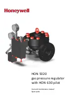
HON 5020 
gas pressure regulator 
with HON


630 pilot 

User and maintenance manual 
Spare parts 

Содержание HON 5020

Страница 1: ...HON 5020 gas pressure regulator with HON 630 pilot User and maintenance manual Spare parts ...

Страница 2: ...porting the gas pressure regulator 33 5 2 Installing the gas pressure regulator 35 5 3 Installing the device connections 36 5 4 Checking the system for leaks 37 6 Adjusting the settings of the device 39 6 1 Adjusting the loading pressure 39 6 2 Adjusting the control stage setpoint 40 6 3 Adjusting the amplifying valve 41 7 Malfunctions 43 7 1 Malfunctions 43 8 Maintenance 45 8 1 Maintenance schedu...

Страница 3: ...ng the device 89 9 3 Disposing of the device 91 10 Appendix 92 10 1 Additional information regarding spare parts 92 10 2 Spare parts for the HON 5020 actuator assembly 94 10 3 Spare parts for two stage HON 630 pilot 98 10 4 Spare parts for load limiting stage 103 10 5 Spare parts for control stage 105 10 6 Spare parts for fine mesh filter 111 10 7 Spare parts for travel indication option 112 10 8 ...

Страница 4: ...umber of different sizes For this reason we are unable to guarantee that illustrations in this user manual coincide with the dimensions of your product In these cases the illustrations should be viewed as a concept sketch Failing to observe the information provided in this document may lead to injuries including death and material damages To ensure the safety any persons handling the product must ...

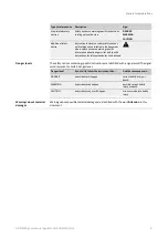
Страница 5: ...y notices is intended to prevent personal injury Safety notices contain the following information Nature and source of the danger Possible consequences associated with the non observance of the notice Procedures for the prevention of personal injury This document contains the following types of safety notices Type of safety notice Description Sign Basic safety notices Superordinate safety notices ...

Страница 6: ...sks and specific instructions for safety procedures can be found The safety notices containing specific instructions are identified with a signal word The signal word represents a certain danger level Danger level If you fail to follow the instruction then And the consequence is DANGER an accident will happen serious bodily injury or death WARNING an accident may happen possible serious bodily inj...

Страница 7: ...uitable for use with natural gas or dry non aggressive industrial gases Note The utilization limits of the device with regard to the medium operating pressure and operating temperature can be gathered from the type plate attached on the device or the technical specifications The use under different operating conditions must be coordinated in consultation with the manufacturer Please observe the fo...

Страница 8: ...es a number of individual expansion options The following individual components are always part of the device HON 905 fine mesh filter Inlet pressure gauge Amplifying valve Control stage including spring adjuster and base plate The following individual components are optional expansions Load limiting stage including spring adjuster and loading pressure gauge Outlet pressure gauge With HON 925 prot...

Страница 9: ...versions and models will be covered specifically as well when there are important differences that need to be pointed out If you have trouble understanding the information in this documentation contact the manu facturer without fail before starting any work on the device 2 3 Labels Markings Illegible information on the device poses a risk of injury due to resulting erroneous opera tion use or inst...

Страница 10: ...plates and the technical specifications Technical specifications see page 16 The type plate of the actuator assembly can be found here Figure No Meaning 1 Front of the actuator assembly For actuator assembly models that use the metric system the information on the name plate will be as follows Figure No Meaning 1 Model name 2 Manufacturer 3 Nominal size 4 Serial number of the device 5 Valve seat d...

Страница 11: ... month year 7 Customer reference number 8 Serial number 9 Differential pressure 10 Temperature range 40 to 175 F 11 Maximum allowable inlet pressure The type plate of the pilot can be found here Figure No Description 1 Front of control stage The details on the type plate have the following meaning Figure No Meaning 1 Name of the device 2 Serial number 3 Maximum allowable pressure 4 Controlled vari...

Страница 12: ...asuring line The diaphragm system in the pilot determines the pressure actual value as a force on the measuring diaphragm and compares it with the force of the pilot spring which is used as reference variable If control deviations are detected based on the results from this comparison the opening position of the actuator assembly s regulating diaphragm will be changed by adjusting the motorization...

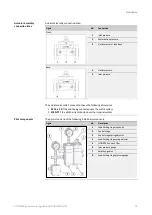
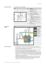
Страница 13: ...dimensions M 14 x 1 5 if the pilot being connected uses the metric system 3 8 NPT if the pilot being connected uses the imperial system The pilot is made up of the following individual components Figure No Description 1 Load limiting stage optional 2 Control stage 3 Control stage spring adjuster 4 Load limiting stage spring adjuster 5 HON 905 fine mesh filter 6 Inlet pressure gauge 7 Amplifying va...

Страница 14: ...onveyed into the control stage and produces a force component that acts on the double diaphragm system from above The pilot s set screw is used to tighten the pilot spring producing a force component that acts on the control stage s double diaphragm system from below The force components being exerted on the double diaphragm system are used by the system in order to compare the setpoint and the pr...

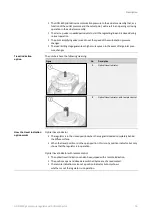
Страница 15: ...anges The numbers have the following meaning Figure No Description 1 Optical travel indicator 2 Optical travel indicator with remote control Optical travel indicator The regulator is in the closed position when the magnet is located completely behind the diffuse surface When the travel position is in the open position this is not a position indicator but only shows that the regulator is in operati...

Страница 16: ...ting as per Class 150 300 600 Class 150 20 bar Class 300 51 bar Class 600 102 bar Flange facing B flange J flange DIN EN 1092 1 Pressure rating as per PN 16 25 40 PN 16 16 bar PN 25 25 bar PN 40 40 bar Flange facing B flange Size PN Class 1 inch mm 2 inch mm 3 inch mm 4 inch mm 5 inch mm Weight lbs kg 1 DN 25 16 150 7 24 184 2 83 72 5 95 151 6 46 164 6 54 166 29 8 13 7 1 DN 25 25 40 300 7 76 197 2...

Страница 17: ... 255 8 98 228 170 0 77 1 4 DN 100 600 15 51 394 5 71 145 9 84 250 10 04 255 8 98 228 205 0 93 0 6 DN 150 16 150 17 76 451 7 56 192 11 61 295 11 85 301 10 59 269 286 6 130 0 6 DN 150 25 40 300 18 62 473 7 56 192 11 97 304 11 69 297 10 59 269 324 1 147 0 6 DN 150 600 20 00 508 7 91 201 11 97 304 11 89 302 10 59 269 425 5 193 0 The HON 640a pilot used in this example weighs 4 19 lbs 1 9 kg Size PN Cl...

Страница 18: ...6 377 234 400 285 254 122 6 55 6 3 6 25 40 384 300 134 1 60 8 3 6 150 374 280 121 7 55 2 3 6 300 394 320 144 9 65 7 3 6 600 412 355 211 2 95 8 4 8 16 536 306 430 460 294 225 1 102 1 4 8 25 549 485 246 5 111 8 4 8 40 564 515 253 4 114 9 4 8 150 549 485 228 0 103 4 4 8 300 566 520 256 7 116 4 4 8 600 586 560 310 0 140 6 6 12 16 611 381 570 460 385 402 0 182 3 6 12 25 624 485 454 0 205 9 6 12 40 639 ...

Страница 19: ...e for a setpoint range Wd 0 3 1 bar Without pressure gauge for outlet pressure The figure below shows the dimensions for the pilot with the control stages for setpoint ranges Wd 0 5 90 bar Without pressure gauge for outlet pressure With outlet pressure gauge pd 1 20 bar With outlet pressure gauge pd 10 90 bar Pilot dimensions and weights ...

Страница 20: ... 7 7 4 0 2 6 4 0 1 0 5 0 0 5 40 11 0 7 7 4 0 2 6 4 0 1 0 5 0 10 90 14 5 12 4 4 0 2 6 4 0 1 0 5 0 Outlet pressure area pd range bar G in H in I in J in K in L in M in N in O in 0 3 1 8 9 3 7 1 7 2 2 3 5 9 1 5 2 3 5 0 9 0 5 40 7 5 1 4 1 7 2 2 2 7 8 2 6 1 10 90 7 5 1 4 1 7 1 3 3 0 8 0 6 1 Criterion Value Nominal diameter 1 DN 25 2 DN 50 3 DN 80 4 DN 100 6 DN 150 Maximum operating pressure 285 psi 19 ...

Страница 21: ... DN 150 Maximum operating pressure 580 psi 40 bar Specific set range Wds Pilot spring No Color Wire diameter mm Control stage 0 3 1 bar 4 4 14 5 psi 0 black 4 5 0 5 2 bar 7 3 29 psi 1 blue 3 6 1 5 bar 14 5 72 5 psi 2 black 4 5 2 10 bar 29 145 psi 3 grey 5 5 20 bar 72 5 290 psi 4 brown 6 3 10 40 bar 145 580 psi 5 red 7 0 10 50 bar 145 725 psi 6 Green 8 7 20 90 bar 290 1305 psi 7 White 9 Load limiti...

Страница 22: ...e fluctuations are 8 bar The properties of the gas conveyed through the devices must meet the requirements speci fied by the DVGW German Technical and Scientific Association for Gas and Water in the latest version of DVGW Code of Practice G 260 A The device s mechanical components do not contain any potential sources of ignition and accordingly do not fall under the scope of ATEX 95 94 9 EC The el...

Страница 23: ...e giving the device away Observe the following rules Only individuals who meet the requirements set forth in this user manual have permis sion to handle the device The device s intended use includes its use in hazardous locations All work with and on the device must be carried out only after the presence of an explosive atmosphere has been fully ruled out Only use the device for the intended purpo...

Страница 24: ...ys consult the directives of your company concerning the protection of the workforce 3 2 Requirements concerning the workforce personal protective gear workplaces Individuals tasked with handling the device must meet the following requirements Personnel Responsibilities Required qualification Skilled person or expert Any work on and with the device Professional training and experience operating pr...

Страница 25: ...la tion Set up Professional training and experience operating pressure equipment and systems Knowledge of the relevant standards and regulations Ability to identify and avoid dangers autonomously Mechanical maintenance personnel Involving mechanical parts Fault finding Maintenance Repairs Professional training and experience operating pressure equipment and systems Knowledge of the relevant standa...

Страница 26: ...othing Safety harness Ear protection Safety boots with protection for electrostatic dis charge ESD Safety goggles Safety gloves To ensure the safe handling of the device the personnel must remain at the workplaces intended for performing their tasks The workplaces for performing the various tasks are at the following locations Task Workplaces Installation Start up Set up Maintenance repairs Decomm...

Страница 27: ...ng lines 31 4 1 Installation examples Configuration Direct acting gas pressure regulator non piloted With expander without noise reduction element downstream of the gas pressure regu lator Configuration Indirect acting gas pressure regulator pilot operated With expander without noise reduction element downstream of the gas pressure regu lator Outlet pressure gauge with protection against overpress...

Страница 28: ...ted Indirect acting slam shut device pilot operated two With expander without noise reduction element downstream of the gas pressure regu lator The numbers have the following meaning No Meaning 1 Safety Shut Off Valve 2 Gas pressure regulator 3 Pilot 4 Safety relief valve 5 Outlet stop valve armature 6 Sensing point for connection lines gray area 7 Feedback line 8 Discharging line 9 Gas pressure r...

Страница 29: ...ntains the outlet pressure constant irrespective of changes in the inlet pressure or changes in the discharge If the consumption is zero the built up motorization pressure pushes the dia phragm onto the seat edge surrounding the flow restrictor by means of the closing spring Monitor regulator unit The outlet pressure is monitored by the upstream monitor regulator unit in addition to the active reg...

Страница 30: ...at the sensing point On a case by case basis and following consultation with the manufacturer even lower flow rates may be al lowed Depending on the specific system design the LuR lengths of the undisturbed pipes upstream of the sensing point must be 2 5 to 5 x DN of the pipe with the specifics depending on the gas pressure regulator model and whether or not there is a pipe expander downstream If ...

Страница 31: ...suring line is LuR min 3 x DN Gas meter pressure losses must be taken into account based on system conditions if applicable 4 4 Operating and measuring lines The lines must be arranged and sized in such a way that the devices intended function will be ensured Measuring line The measuring line transmits the pressure process value from the sensing point to the measuring diaphragm of a controller or ...

Страница 32: ... least five times as large as the total of the individual lines cross sectional areas For primary slam shut devices it is recommended to route the slam shut devices vent lines separately Vent lines must not be grouped together with blowdown lines Discharging line When using indirect acting pilot operated slam shut devices the discharg ing line is used to divert the exhaust gas from the pilot into ...

Страница 33: ...ppropriate hoisting equipment must correspond at least to the weight of the load to be transported Always stand clear of suspended loads Ensure that no person is within the danger zone A mobile workshop crane is suitable for use as hoisting equipment A pallet jack or forklift is also suitable for intraplant transportation The following are adequate for use as slings Ropes Belts Chains The hoisting...

Страница 34: ...0 during transport 2 Hook the sling into the eye bolt 3 Lift the HON 5020 Slowly and carefully transport the HON 5020 to the location where it will be installed If the travel indication option is present proceed as follows 1 Remove the protective caps 2 Install the ring bolts included in delivery and attach the slings to the ring bolts 3 Lift the HON 5020 Slowly and carefully transport the HON 502...

Страница 35: ... the location where it will be installed The device needs to be installed in the piping in a horizontal and level position If you want to use a different installation position consult with the manufacturer first Pay attention to the direction of flow for the gaseous fluid as marked on the body 3 Secure and support the device s position in such a way that the device can be installed in the piping w...

Страница 36: ...o be installed 5 Outlet pressure measuring impulse line measuring impulse line operating line needs to be installed Prepare the following materials Pipes connecting pieces and fittings as per the specifications in the Technical specifica tions see page 16 Shut off devices for the operating and measuring impulse lines as well as other acces sories as required as per the Basics for installing the de...

Страница 37: ... undergo a leak test at the set up location in ac cordance with applicable international and national standards Risk of serious injury posed by pressurized components moving in an uncontrolled manner when handled improperly If not handled properly or in the event of a defect gas can escape from pressurized compo nents under high pressure and cause serious injuries and even death Before you start w...

Страница 38: ...e outlet stop valve armature 2 Apply the test medium to all detachable pipe joints 3 Observe the test medium on all detachable pipe joints for several minutes If then no foam or bubbles are formed the system is leak proof the system may be put into operation foam or bubbles are formed the affected pipe joint is leaking the system may not be put into operation Proceed with step 4 Step Description 4...

Страница 39: ...g pressure will be set to 5 10 bar over outlet pressure pd For the current loading pressure please check the load limiting stage pressure gauge reading Proceed as follows Figure Step Description 1 Unscrew the lock nut 1 on the set screw 2 located on the underside of the pilot s load limiting stage 2 Turn the set screw until the load limiting stage pressure gauge shows the setpoint you want Counter...

Страница 40: ...oint for outlet pressure pd The shut off devices for the blowdown lines are closed The inlet pressure is present upstream of the inlet shut off device Proceed as follows Figure Step Description 1 Unscrew the lock nut 1 on the set screw 2 located on the underside of the pilot s control stage 2 Loosen the set screw 2 until the tension in the pilot spring has been relieved 3 Open the inlet shut off d...

Страница 41: ...re regulator exhibits a sluggish response to changes in the manipulated variable the response times can be shortened If the gas pressure regulator s dynamic response to changes in the manipulated variable is too fast and this results in oscillations the gas pressure regulator s response can be slowed down Proceed as follows Figure Step Description 1 Remove the cap from the amplifying valve If then...

Страница 42: ...ctuator assem bly s control behavior As soon as you achieve the actuator assembly response you want stop changing the spindle s position 2b Use a flat blade screwdriver to unscrew the spindle 1 out from the sleeve turn by turn while monitoring the actuator assem bly s control behavior As soon as you achieve the actuator assembly response you want stop changing the spindle s position 3 Put the ampl...

Страница 43: ...t is not building up suffi cient motorization pressure Maintaining the pilot see page 53 The actuator assembly is opening closing too slowly The pilot s response speed is not correct Adjust the pilot s response speed Adjusting the amplifying valve see page 41 The actuator assembly s diaphragm is faulty Maintaining the actuator assembly see page 50 replace the actuator assembly if necessary Low flo...

Страница 44: ...screws are not tightened properly Check the flow restrictor s screws to make sure they have a tight fit Unstable outlet pressure behavior oscillations The regulator is not being operated with sufficient differential pressure Increase the differential pressure with the regulator The actuator assembly s diaphragm is too soft Check the actuator assembly s diaphragm contact the manufac turer if necess...

Страница 45: ...enance intervals specified below may have to be adjusted based on the relevant operating requirements and experience Maintenance must be carried out in compliance with all federal and state laws and regulations as well as with the local rules and regulations set forth by the relevant utilities and authorities and any other applicable regula tions Perform the following maintenance and repairs withi...

Страница 46: ...e in working condition and they must be replaced if necessary Because of this it is recommended to have the following servicing parts ready for maintenance in order to avoid downtimes For the pilot Compression spring s and if applicable spring plates Pressure gauge s Filter insert For the actuator assembly Closing spring Flow restrictor 2 Preparing special tools In addition to standard tools have ...

Страница 47: ... as a reference The numbers have the following meaning No Meaning 1 Inlet stop valve armature 2 Gas pressure regulator 3 Pressure gauge 4 Outlet stop valve armature 5 Valve for blowdown line 6 Blowdown line Proceed as follows Step Description 1 Close the outlet stop valve armature 4 2 Close the inlet stop valve armature 1 3 Depressurize the pilot Turn the set screw on the pilot s control stage and...

Страница 48: ...o perform maintenance on the actua tor assembly only The motorization line between the pilot and the actuator assembly needs to be uninstalled The actuator assembly can remain in the gas regulating line The pilot including the remaining pipes with the exception of the motorization line can remain in the gas regulating line You want to perform maintenance on both the actuator assembly and the pilot...

Страница 49: ...r with HON 630 pilot 49 To remove the pilot follow the steps below Figure Step Description 1 Disconnect all the pilot pipes Inlet pressure line 1 Motorization line 2 Measuring impulse line 3 Vent line 4 Outlet pressure line 5 2 Remove the pilot ...

Страница 50: ...first be removed Tightening torques of the bolts securing the regulator top cover are as follows Nominal size Pressure rating Screw specifications Tightening torque 1 DN 25 Class 150 300 600 5 8 UNC grade 7 203 Nm 150 ft lbs PN 16 25 40 M16 2 DN 50 Class 150 300 600 5 8 UNC grade 7 203 Nm 150 ft lbs PN 16 25 40 M16 3 DN 80 Class 150 5 8 UNC grade 7 203 Nm 150 ft lbs PN 16 M16 3 DN 80 Class 300 600...

Страница 51: ...pring 1 and the diaphragm unit 2 3 Remove the flow restrictor If the flow restrictor is damaged Replace the flow restrictor with a new one 4 Remove the O ring 1 the noise reduction element 2 and the supporting shim 3 Replace the O ring with a new lubricated O ring Check the noise reduction element and the support disc for damage and replace them if necessary 5 If the diaphragm is damaged Dismantle...

Страница 52: ...ble the regulator unit Push the lid down when screwing down the screws until they are completely secured Refer to the additional tightening torque information at the beginning of this topic Tighten the screws in a criss cross sequence Depending on what you want to do next proceed as indicated in the relevant section Maintaining the pilot see page 53 Completing the maintenance see page 88 Next task...

Страница 53: ... if the components start moving in an uncontrolled manner e g fall down from the working surface or topple over Place removed components exclusively on level horizontal working surfaces with enough load bearing capacity If necessary secure removed components so that they will not fall or topple over Wear the required personal protective equipment Exercise caution when performing the relevant tasks...

Страница 54: ...ng stage 1 and the base plate 2 and remove the load limiting stage 3 Replace the 7 O rings 1 and the O ring 2 over the washer 3 with new greased ones 4 Turn the base plate over 5 Replace the 4 sealing rings 1 with new greased ones Lubricate the thread surfaces before screwing the fittings back in 6 Remove the cap from the amplifying valve ...

Страница 55: ... pull it out towards the back 9 Replace the O ring 1 with a new greased O ring 10 Take the spindle Replace the O ring 1 and the retaining ring 2 with new greased ones 11 Lubricate the thread surfaces Slide the spindle into the sleeve and screw in the spindle all the way to the position shown The notch on the spindle should be flush with the sleeve s front edge ...

Страница 56: ...y may result if the components start moving in an uncontrolled manner e g fall down from the working surface or topple over Place removed components exclusively on level horizontal working surfaces with enough load bearing capacity If necessary secure removed components so that they will not fall or topple over Wear the required personal protective equipment Exercise caution when performing the re...

Страница 57: ...ews 1 and lift off the upper cover 2 3 Unscrew the fitting 1 on the upper cover Replace the sealing ring 2 with a new greased sealing ring Lubricate the thread surfaces Screw the fitting 1 back in 4 Remove the spring from the cap 5 Unscrew the cap 1 while using an open end wrench to hold the diaphragm plate 2 in place so as to prevent the components from turning Replace the O ring 3 in the cap wit...

Страница 58: ...cting piece 7 Remove the diaphragm disc 1 and the diaphragm 2 8 Remove the valve body from the spring housing Screw the assembly aid 1 into the valve insert 2 9 Hold on to the connecting piece 1 and pull out the valve insert 2 Remove the connecting piece 10 Replace the valve insert with a new one Insert a new greased O ring 1 ...

Страница 59: ... of the diaphragm that has a depression at the center should be facing upward 13 Lightly coat the thread surfaces with threadlocker Screw the hex nut back onto the connect ing piece Observe the tightening torque information provided in the table before this section 14 Insert the connecting piece into the valve body Make sure that the holes 1 2 are aligned 15 Align the valve body 1 as shown Hold th...

Страница 60: ... and the new piston Old piston 1 Castellated nut closed New piston 2 Castellated nut open 18 Lightly coat the thread surfaces with threadlocker Put the cap in place Tighten the cap while using an open end wrench to hold the diaphragm plate in place so as to prevent the components from turning Observe the tightening torque information provided in the table before this section 19 Remove the assembly...

Страница 61: ...se until it will not rotate any further Use a marker or pen to mark the position on the body and on the convoluted dia phragm 23 Use the cap to turn the diaphragm by hand counterclockwise until it will not rotate any further Use a marker or pen to mark the position on the body 24 Use the cap to turn the diaphragm by hand so that the marking on the diaphragm is right between the two markings on the...

Страница 62: ...crews 1 hand tight at first 28 Loosen the base plate screws and remove the base plate Important While removing the base plate parts on the inside may fall out from the spring housing by accident 29 Remove the lower spring plate 3 the compression spring 2 and the upper spring plate 1 from the spring housing Lubricate the spring plates depressions and reinsert the parts into the spring housing in th...

Страница 63: ...ndicated in the relevant section For the multi stage pilot version Maintaining the load limiting stage see page 82 For the single stage pilot version Maintaining the fine mesh filter see page 85 8 5 3 Maintaining the control stage with a metal bellows assembly Crush and impact hazard posed by components falling or toppling over accidentally When working with heavy components that have been removed...

Страница 64: ...in this section Part Tightening torque Step Closing cap 20 Nm 15 ft lbs 21 Cylinder screws 6 Nm 5 ft lbs 31 Hex bolt 12 Nm 9 ft lbs 35 Hex bolt 12 Nm 9 ft lbs 37 Proceed as follows Figure Step Description 1 Release the tension on the pilot spring by loosening the hex flange nut 1 and unscrewing the spring adjuster 2 a few turns 2 Loosen the screws and lift off the upper cover 3 Unscrew the fitting...

Страница 65: ...portant While removing the cover parts on the inside may fall out from the spring housing by accident 6 Remove the lower spring plate 1 the axial washers 2 and the axial needle roller bearing 3 from the spring housing 7 Remove the compression spring 1 and the upper spring plate 2 from the spring housing 8 Unscrew the metal bellows internal screws 1 from the lower section of the spring housing ...

Страница 66: ... spring housing 10 Pull the valve body including the metal bellows upwards in order to remove it as a complete unit from the spring housing 11 Unscrew the cap 1 while using an open end wrench to hold the diaphragm plate 2 in place so as to prevent the components from turning 12 Replace the O ring with a new greased O ring 13 Remove the pistons from the connecting piece ...

Страница 67: ...ate 1 and the diaphragm 2 15 Screw the assembly aid into the valve insert 16 Pull out the valve insert 17 Replace the valve insert with a new one Insert a new greased O ring 1 18 Align the valve body as shown Insert the assembly aid with the milled surface facing upward towards the piston opening into the valve body ...

Страница 68: ...rence between the old and the new piston Old piston 1 Castellated nut closed New piston 2 Castellated nut open 21 Lightly coat the thread surfaces with threadlocker Put the cap 1 in place Tighten the cap 1 while using an open end wrench to hold the diaphragm plate 2 in place so as to prevent the components from turning Observe the tightening torque information provided in the table before this sec...

Страница 69: ...the diaphragm by hand clockwise until it will not rotate any further Use a marker or pen to mark the position on the body and on the convoluted dia phragm 26 Use the cap to turn the diaphragm by hand counterclockwise until it will not rotate any further Use a marker or pen to mark the position on the body 27 Use the cap to turn the diaphragm by hand so that the marking on the diaphragm is right be...

Страница 70: ...including the corresponding washers from the underside of the spring housing Observe the tightening torque information provided in the table before this section 32 Lubricate the upper spring plate s depres sions 2 Reinsert the upper spring plate 2 and the compression spring 1 into the spring housing in the right order and alignment 33 Lubricate the lower spring plate s depres sions 1 Reinsert the ...

Страница 71: ...ening torque information provided in the table before this section 36 Turn the spring housing Place the spring back on the cap 37 Lubricate the thread surfaces Check to make sure that the diaphragm marking is still in the center position see step 27 Place the upper cover back in place Tighten the screws hand tight at first 38 Unscrew the adjusting screw 2 and remove it from the base plate Clean an...

Страница 72: ...ntrolled manner e g fall down from the working surface or topple over Place removed components exclusively on level horizontal working surfaces with enough load bearing capacity If necessary secure removed components so that they will not fall or topple over Wear the required personal protective equipment Exercise caution when performing the relevant tasks Observe the following cleaning instructio...

Страница 73: ...ription 1 Release the tension on the pilot spring by loosening the hex flange nut 1 and unscrewing the spring adjuster 2 a few turns 2 Unscrew the diaphragm cover s screws 1 3 Unscrew the screw in fitting 4 Remove the diaphragm cover 5 Remove the spring 1 from the hex nut Maintaining the control stage ...

Страница 74: ...om ponents from turning 7 Remove the pressure piece 1 the dia phragm 2 and the diaphragm plate 3 8 Unscrew the diaphragm housing s screws 1 Remove the screws and the bonded seals 2 9 Hold the valve body 2 in place and lift the diaphragm housing off 1 10 Unscrew the upper connecting piece 1 while using an open end wrench to hold the diaphragm plate 2 in place so as to prevent the components from tu...

Страница 75: ...Remove the diaphragm plate 1 and the diaphragm 2 13 Remove the valve body from the spring housing Screw the assembly aid 1 into the valve insert 2 14 Hold on to the connecting piece 1 and pull out the valve insert 2 Remove the connecting piece 15 Replace the valve insert with a new one Insert a new greased O ring 1 ...

Страница 76: ... of the diaphragm that has a depression at the center should be facing upward 18 Lightly coat the thread surfaces with threadlocker Screw the hex nut back onto the connect ing piece Observe the tightening torque information provided in the table before this section 19 Insert the connecting piece into the valve body Make sure that the holes 1 2 are aligned 20 Align the valve body 1 as shown Hold th...

Страница 77: ...g piece Risk of confusion Please observe the characterizing difference between the old and the new piston Old piston 1 Castellated nut closed New piston 2 Castellated nut open 23 Take the upper connecting piece Replace the O ring 1 with a new greased O ring 24 Lightly coat the thread surfaces with threadlocker Screw the connecting piece 1 back in place while using an open end wrench to hold the di...

Страница 78: ...gn the cross hole of the lower con necting piece correctly with the valve insert Use the upper connecting piece to turn the diaphragm by hand clockwise until it will not rotate any further Use a marker or pen to mark the position on the body and on the convoluted diaphragm 29 Use the upper connecting piece to turn the diaphragm by hand counterclockwise until it will not rotate any further Use a ma...

Страница 79: ... 2 in place and put the diaphragm housing 1 back in place 34 Replace the bonded seals 2 with new ones Lubricate the thread surfaces Tighten the diaphragm housing s screws 1 in a criss cross sequence Observe the tightening torque information provided in the table before this section 35 Replace the diaphragm 2 with a new one Put the diaphragm plate 3 the new diaphragm 2 and the pressure piece 1 back...

Страница 80: ...he pressure piece in place so as to prevent the com ponents from turning Observe the tightening torque information provided in the table before this section 37 Put the spring 1 back in place 38 Take the diaphragm cover Replace the O ring 1 with a new greased O ring 39 Put the diaphragm cover back in place 40 Replace the O ring 1 with a new greased O ring ...

Страница 81: ...ovided in the table before this section 43 Loosen the base plate screws Remove the base plate Important While removing the base plate parts on the inside may fall out from the spring housing by accident 44 Remove the lower spring plate 3 the compression spring 2 and the upper spring plate 1 from the spring housing Lubricate the spring plates depressions and reinsert the parts into the spring housi...

Страница 82: ...proceed as indicated in the relevant section For the multi stage pilot version Maintaining the load limiting stage see page 82 For the single stage pilot version Maintaining the fine mesh filter see page 85 8 5 5 Maintaining the load limiting stage Crush and impact hazard posed by components falling or toppling over accidentally When working with heavy components that have been removed or are yet ...

Страница 83: ...hen tightening fasteners observe the following tightening torques Part Tightening torque Step Socket cap screw 12 Nm 9 ft lbs 35 Proceed as follows Figure Step Description 1 27 Same as in Maintaining the control stage with a diaphragm assembly see page 56 28 Turn the load limiting stage Unscrew the socket cap screws and washers on the base plate 29 Remove the base plate Replace the O ring 1 with a...

Страница 84: ...e base plate 34 Replace the O ring 1 with a new greased O ring 35 Put the base plate back in place Insert the base plate back into the body Tighten the screws with the washers in a criss cross sequence Refer to the additional lubricant and tightening torque information at the beginning of this topic Proceed as follows Maintaining the fine mesh filter see page 85 Next task ...

Страница 85: ...t first be removed Observe the tightening torques below when following the instructions in this section Part Tightening torque Step Base plate hex nut 10 Nm 8 ft lbs 7 Fitting 40 Nm 30 ft lbs 9 Proceed as follows Figure Step Description 1 Unscrew the nuts 1 and washers 2 Remove the base plate 3 from the body 2 Remove the filter insert 1 and clean it 3 Check the filter cartridge for damage and repl...

Страница 86: ...plate on the body Tighten the nuts 1 and washers 2 for the base plate 3 in a criss cross sequence Observe the tightening torque information provided in the table before this section 8 Unscrew the fittings and replace the sealing rings 1 with new greased ones 9 Install the greased fittings back in place Observe the tightening torque information provided in the table before this section Proceed as f...

Страница 87: ...levant tasks Observe the following cleaning instructions Before assembly all parts must be cleaned in order to remove any foreign particles swarf and soiling If screws bolts or washers are replaced with identical new parts any oil on these new parts must first be removed When tightening fasteners observe the following tightening torques Part Tightening torque Step Hex nut 12 Nm 9 ft lbs 1 2 3 Proc...

Страница 88: ...n the assemblies Use a second spanner wrench for securing when loosening and tightening pipe joints Proceed as follows Figure Step Description 1 Reinstall all the pipes you removed previ ously on the actuator assembly Inlet pressure line 1 Motorization line 2 Outlet pressure line 5 2 Reinstall all the pipes you removed previ ously on the pilot Inlet pressure line 1 Motorization line 2 Measuring im...

Страница 89: ...packaging and in the same condition it was de livered and check it annually for damage and soiling Consider the storage pe riod in the maintenance cycles Note Please also observe any storage information provided on the packaging The following rules apply to the storage of spare parts Apply an appropriate protective agent to assemblies at risk of corrosion If stored correctly O rings and gaskets sh...

Страница 90: ...top valve armature 1 3 Depressurize the pilot Turn the set screw on the pilot s control stage and the set screw on the pilot s load limiting stage as well if applicable clockwise until the pressure in the pilot is equalized 4 Open the valve 5 in the blowdown line 6 to discharge the pressure between the inlet and the outlet valves When conducting work involving the pipework please always observe th...

Страница 91: ...sing of the device Comply with the legally stipulated disposal rules Observe the following details pertaining to the appropriate disposal not all of the items may be applicable to your device Dispose of the metals according to their types and grades steel scrap cast iron scrap light alloy scrap nonferrous heavy metal scrap synthetic rubber scrap electronic scrap Recycle elements made of synthetic ...

Страница 92: ...mpany operating the device is allowed to replace in the event of a fault or defect Miscellaneous spare part Parts that are listed in the spare part drawings in addition to maintenance and servicing parts so as to improve communications between the cus tomer and the manufacturer but that are not allowed to be ordered or replaced without first contacting the manufacturer The spare parts always requi...

Страница 93: ...nominal size and pressure rating Maintenance parts for two stage HON 630 pilot for the three setpoint ranges Additional list without outlet pressure gauge Additional list with outlet pressure gauge Wd 0 3 20 bar Additional list with outlet pressure gauge Wd 10 90 bar Servicing parts for two stage HON 630 pilot for the three setpoint ranges Additional list with outlet pressure gauge Wd 0 3 20 bar A...

Страница 94: ... 201 MZ 001 Flow restrictor 75 201 MZ 004 Flow restrictor 50 201 MZ 006 Flow restrictor 25 201 MZ 008 1 D 1 Carrier plate 201 MN 001 1 E 1 Metal foam 201 MF 001 2 8 1 Diaphragm up to 50 bar DP 202 MJ 012 2 8 1 Diaphragm up to 70 bar DP 202 MJ 013 2 13 1 O ring 730ODVN229 2 A 1 Closing spring SS1075 2 B 4 Screws 710BCFE03010 2 C 1 Flow restrictor 100 202 MZ 011 Flow restrictor 75 202 MZ 019 Flow re...

Страница 95: ...03 MN 001 3 E 1 Metal foam 203 MF 001 4 8 1 Diaphragm up to 50 bar DP 204 MJ 003 4 8 1 Diaphragm up to 70 bar DP 204 MJ 004 4 13 1 O ring 730ODVN244 4 A 1 Closing spring 10024055 4 B 6 Screws 710BCFE03010 4 C 1 Flow restrictor 100 204 MZ 010 Flow restrictor 75 204 MZ 016 Flow restrictor 50 204 MZ 012 Flow restrictor 25 204 MZ 017 4 D 1 Carrier plate 204 MN 002 4 E 1 Metal foam 204 MF 001 6 8 1 Dia...

Страница 96: ...ame Part no 2 2 Class 150 300 PN 16 25 40 series 5020 IGP spare parts kit 202 MS 008 8 1 Diaphragm up to 50 bar DP 202 MJ 012 13 1 O ring 730ODVN229 Nominal size No Letter Qty Name Part no 2 2 Class 600 5020 series IGP spare parts kit 202 MS 009 8 1 Diaphragm up to 70 bar DP 202 MJ 013 13 1 O ring 730ODVN229 Nominal size No Letter Qty Name Part no 3 3 Class 150 300 PN 16 25 40 series 5020 IGP spar...

Страница 97: ...gm up to 50 bar DP 204 MJ 003 13 1 O ring 730ODVN244 Nominal size No Letter Qty Name Part no 4 4 Class 600 5020 series IGP spare parts kit 204 MS 009 8 1 Diaphragm up to 70 bar DP 204 MJ 004 13 1 O ring 730ODVN244 Nominal size No Letter Qty Name Part no 6 6 Class 150 300 600 PN 16 25 40 series 5020 IGP spare parts kit 206 MS 001 8 1 Diaphragm 50 70 bar DP 10011307 13 1 O ring 730ODVN261 ...

Страница 98: ...Appendix HON 5020 gas pressure regulator with HON 630 pilot 98 10 3 Spare parts for two stage HON 630 pilot Spare parts drawing for pilot with larger diaphragm assembly ...

Страница 99: ...Appendix HON 5020 gas pressure regulator with HON 630 pilot 99 Spare parts drawing for pilot with diaphragm assembly ...

Страница 100: ...Appendix HON 5020 gas pressure regulator with HON 630 pilot 100 Spare parts drawing for pilot with metal bellows assembly ...

Страница 101: ...2 18 842 Pressure gauge for Wds 0 3 20 bar The following bill of materials applies to the version with a pressure gauge for a specific setpoint range of Wds 0 3 20 bar No Name Larger diaphragm assembly Part no Diaphragm meas uring unit Metal bellows measuring unit 48 Gasket 18 842 18 842 Pressure gauge for a specific setpoint range of Wds 10 90 bar The following bill of materials applies to the ve...

Страница 102: ... of materials applies to the version with a pressure gauge for a specific setpoint range of Wds 0 3 20 bar No Name Larger diaphragm assembly Part no Diaphragm meas uring unit Metal bellows measuring unit 42 Pressure gauge for the following specific setpoint ranges Wds 0 3 1 bar 27 933 Wds 0 5 2 bar 27 933 Wds 1 5 bar 27 933 Wds 2 10 bar 26 890 Wds 5 20 bar 100 418 RMK 44 Protection against overpre...

Страница 103: ...ing unit Metal bellows measuring unit Wds 10 50 bar 26 283 26 283 Wds 20 90 bar 26 285 10 4 Spare parts for load limiting stage The left half of the figure shows the standard design without an electric actuator The right half shows the version with the electric actuator installed Spare parts drawing for load limiting stage ...

Страница 104: ...bled 10 000 186 118 O ring 20 332 119 Convoluted diaphragm 10 000 191 2 units 120 Snap on gasket 10 000 066 2 units 126 O ring 20 293 130 Plate pre assembled 10 010 480 133 O ring 20 226 No Name Part no 108 Spring collar 10 000 073 109 Compression spring 10 000 072 Maintenance parts for load limiting stage Servicing parts for load limiting stage ...

Страница 105: ...Appendix HON 5020 gas pressure regulator with HON 630 pilot 105 10 5 Spare parts for control stage Spare parts drawing for control stage with dia phragm assembly ...

Страница 106: ...Piston pre assembled 10 000 186 118 O ring 20 332 119 Convoluted diaphragm 10 000 191 2 units 120 Snap on gasket 10 000 066 2 units 125 Hex flange nut 13 136 No Name Part no 108 Spring collar See No 22 109 Compression spring See No 23 Maintenance parts for control stage with dia phragm assembly Servicing parts for control stage with diaphragm assembly ...

Страница 107: ... with HON 630 pilot 107 The left half of the figure shows the standard design without an electric actuator The right half shows the version with the electric actuator installed Spare parts drawing for control stage with metal bellows assembly ...

Страница 108: ...92 Gasket 10 021 765 196 O ring 20 326 No Name Part no 161 Spring plate for the following specific setpoint ranges Wds 10 50 bar 10 011 774 Wds 20 90 bar 10 011 774 162 Compression spring for the following specific setpoint ranges Wds 10 50 bar green 10 000 149 Wds 20 90 bar white 10 010 444 For installation on electric actuator 190 Spring plate for the following specific setpoint ranges Wds 10 50...

Страница 109: ...Appendix HON 5020 gas pressure regulator with HON 630 pilot 109 Spare parts drawing for control stage with larger diaphragm assembly ...

Страница 110: ...6 264 Spring collar 10 000 114 265 Compression spring 10 000 156 268 Hex flange nut 13 136 273 Bonded seal 20 908 275 Piston pre assembled 10 000 186 277 O ring 20 225 278 Valve insert 10 000 061 282 O ring 20 093 No Name Part no 264 Spring collar 10 000 114 265 Compression spring 10 000 156 Maintenance parts for control stage with larger diaphragm assembly Servicing parts for control stage with l...

Страница 111: ...ON 630 pilot 111 10 6 Spare parts for fine mesh filter No Name Part no 4 Gasket 18 842 2 units 7 O ring 20 317 9 O ring 20 282 No Name Part no 6 Filter insert 26 183 Spare parts drawing for HON 905 fine mesh filter Maintenance parts Servicing parts ...

Страница 112: ...N 630 pilot 112 10 7 Spare parts for travel indication option Spare part drawings Optical travel indicator Optical travel indicator with remote control No Qty Name NBR Part no FKM Part no 12 1 O Ring 100448 RMK 20823 Maintenance and servic ing parts ...

Страница 113: ...he following lubricants for the actuator assembly Components Remark Lubricant Part no O rings Silicone grease 27 052 Diaphragm grip body Grease the dia phragm grip body on all sides All fastening screws Assembly lubricant 27 091 All fittings Important All parts must be coated slightly Use the following threadlocker for the pilot Application Threadlocker Part no Cap threads Hex nut threads LOCTITE ...

Страница 114: ...way South Houston TX 77042 Phone 1 602 293 1866 Option 4 Honeywell Gas Technologies GmbH Osterholzstrasse 45 23123 Kassel Germany Phone 49 0 561 5007000 Emaar Business Park Building 2 Sheikh Zayed Road PO Box 232362 Dubai United Arab Emirates Phone 97144505800 Honeywell Engineering Sdn Bhd 1st Floor Block B No 10 Jalan Bersaru 13 4 46200 Petailing Jaya Selangor DE Malaysia Phone 603 7626 57000 A1 ...

Отзывы: