background image

Rev A

12

Document 800-04354

 04/09

6.

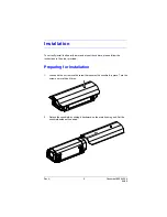
Reassemble the housing unit by closing the upper body and latching the lid tight.

7.

If applicable, reinstall the sunshield by sliding it across the top of the housing.

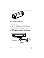
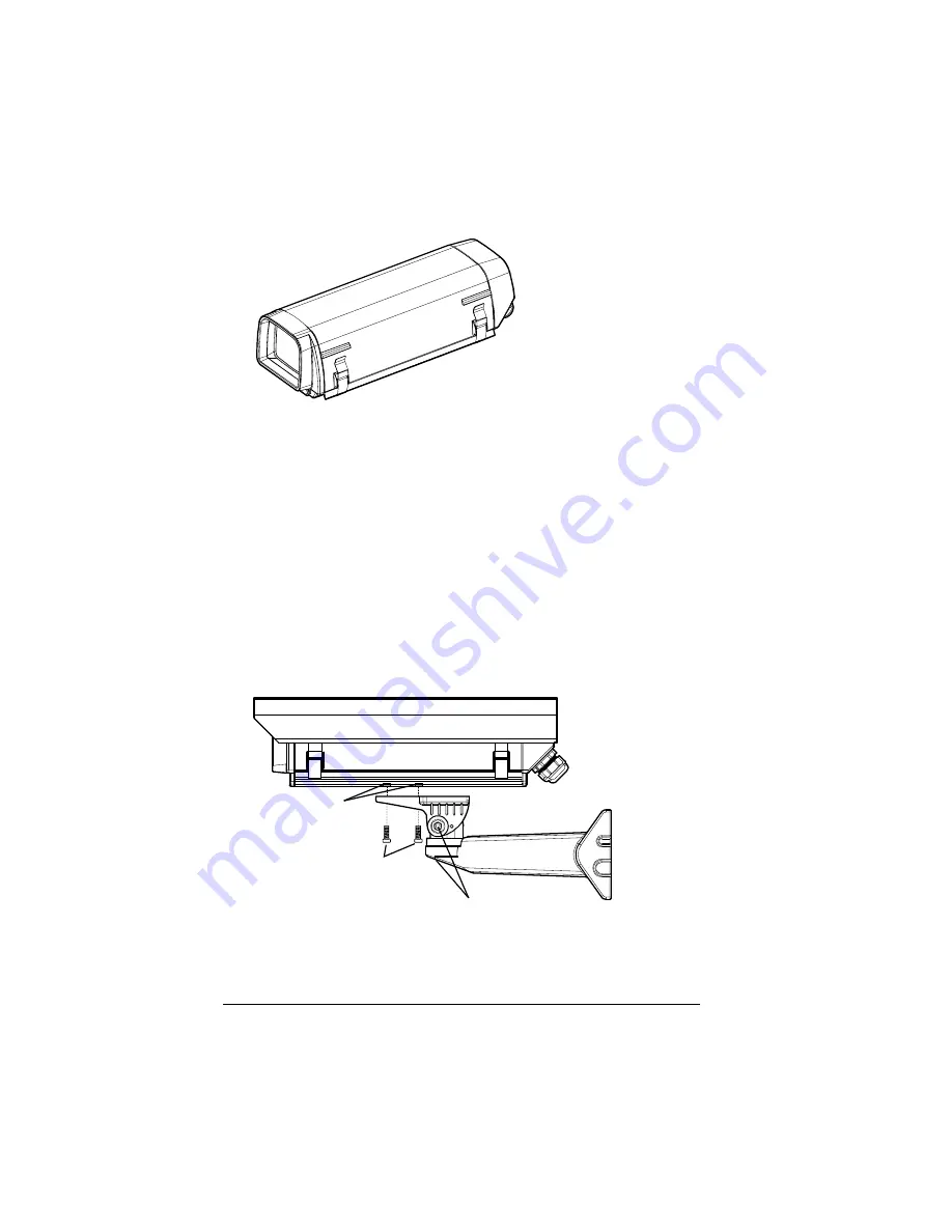
Mounting the Wall Bracket

To mount the wall bracket:
1.

Use fasteners of an appropriate size and type to attach the bracket to the wall 
surface. Position the housing so that it allows for viewing the selected area.

2.

Locate the two nuts that freely slide along the channel. Position the nuts 
approximately 2 inches from each other. 

3.

Place the housing onto the mount, aligning the holes. Insert the two 1/4"-20 UNC 
screws (supplied) through the mount and into the nuts and tighten to secure the 
assembly. 

4.

Adjust the moveable arm of the wall bracket to attain the desired position. 

5.

Tighten the bolt located at the pivot point of the moveable arm and tighten the set 
screw.

6. Latch the lid.

2. Position the 

two nuts 2” 

apart.

3. Secure the housing with 

2 x 1/4 x 20 UNC screws.

4. Adjust the arm, 

then tighten the 

set screws.

1. Attach the 

bracket to the 

wall using 4 

sheet metal 

screws.

Содержание HHC12 Series

Страница 1: ...Install Guide HHC12 Series Document 800 04354 04 09 Rev A 12 Inch Camera Enclosure ...

Страница 2: ...Rev A 2 Document 800 04354 04 09 Revisions Revision Date Revisions A 04 09 New document updated to Honeywell standards based on 900 0559 ...

Страница 3: ...sure compliance with electrical safety standards Explanation of Graphical Symbols RISK OF ELECTRIC SHOCK DO NOT OPEN CAUTION TO REDUCE THE RISK OF ELECTRIC SHOCK DO NOT REMOVE THE COVER NO USER SERVICEABLE PARTS INSIDE REFER SERVICING TO QUALIFIED SERVICE PERSONNEL THIS SYMBOL INDICATES THAT DANGEROUS VOLTAGE CONSTITUTING A RISK OF ELECTRIC SHOCK IS PRESENT WITHIN THE UNIT THIS SYMBOL INDICATES TH...

Страница 4: ...Rev A 4 Document 800 04354 04 09 ...

Страница 5: ... 6 Ordering Information 6 Before You Begin 7 Unpack Everything 7 Equipment Required 7 Installation 8 Preparing for Installation 8 Connecting the Heater Blower HHC12WM2 Model Only 9 Mounting the Camera 10 Mounting the Wall Bracket 11 Maintenance 12 Specifications 13 ...

Страница 6: ...Rev A 6 Document 800 04354 04 09 ...

Страница 7: ... rack Removeable body for easy servicing Indoor outdoor applications Epoxy powder coating for corrosion resistance IP66 rated Model No Description Housing Models HHC12WM 12 inch housing with sunshield and HHMW13 wall mount HHC12WM2 12 inch housing with sunshield heater kit blower kit and HHMW13 wall mount Optional Components HHMC21J Ceiling J mount 21 high 30 lbs 13 5 kg max HHMCMA Corner mount ad...

Страница 8: ...ion Screwdriver camera and camera cable power supply Housing Model Packing Includes HHC12WM One 12 inch housing with sunshield One desiccant bag One HHMW13 wall mount Four 1 4 x 20 UNC machine screws Four 14 1 1 4 sheet metal screws HHC12WM2 One 12 inch housing with heater blower and sunshield One desiccant bag One HHMW13 wall mount Four 1 4 x 20 UNC machine screws Four 14 1 1 4 sheet metal screws...

Страница 9: ...amera please follow the instructions in the order provided Preparing for Installation 1 Loosen but do not remove the screw that secures the sunshield in place Turn the screw no more than 5 times 2 Detach the sunshield by sliding it backward on the main housing unit Set the sunshield aside until needed ...

Страница 10: ... for use later Connecting the Heater Blower HHC12WM2 Model Only Feed the external power supply not included through one of the compression glands then connect to the circuit board The recommended power supply is 24 VAC 50VA J1 AC R1 GND C1 GND AC OUT FAN GND HEATER Ground AC Out VDC to Blower B Ground VAC Out AC IN Ground to Heater to camera Compression glands Caution These wires must be connected...

Страница 11: ...ver to better accommodate your camera 4 Place the mounting plate in its original position and secure the assembly by tightening the Philips panhead screw through the mounting plate into the lower body of the housing 5 Run the camera cable through the compression glands and make all necessary electrical connections refer to the guide that came with your camera Ensure that the compression glands are...

Страница 12: ...s that freely slide along the channel Position the nuts approximately 2 inches from each other 3 Place the housing onto the mount aligning the holes Insert the two 1 4 20 UNC screws supplied through the mount and into the nuts and tighten to secure the assembly 4 Adjust the moveable arm of the wall bracket to attain the desired position 5 Tighten the bolt located at the pivot point of the moveable...

Страница 13: ...aintenance prolongs the operational life and appearance of equipment On a regular basis do the following Maintain picture quality by cleaning the viewing area window with a soft cloth and a mixture of mild detergent and water Verify that all mounting hardware is secure ...

Страница 14: ...x 230 mm Viewing area 2 9 x 2 4 in 73 x 61 mm Viewing window Clear 1 8 double density glass Construction Extruded and die cast aluminum Finish Epoxy powder coating Environment Indoor outdoor 4 F to 140 F 20 C to 60 C IP66 rated Camera mounting Slotted camera sled Recommended mounts HHMC21J Ceiling J mount HHMW13 Wall mount HHMCMA Corner mount adapter HHMPMA Pole mount adapter Cable entry 3 compres...

Страница 15: ... Supply 24 VAC Power Consumption 20 W Heater ON Heater turns ON at 41 F 5 C Heater OFF Heater turns OFF at 59 F 15 C Blower HHC12WM2 Specifications Power Supply 24 VAC Power Consumption 3 4 W Blower ON Blower turns ON at 95 F 35 C Blower OFF Blower turns OFF at 68 F 20 C ...

Страница 16: ...28 River Road West Parramatta NSW 2150 Australia www honeywellsecurity com au 61 2 8837 9300 Honeywell Systems Group Asia 35F Tower A City Center 100 Zun Yi Road Shanghai 200051 China www asia security honeywell com 86 21 5257 4568 Honeywell Systems Group Middle East N Africa Post Office Box 18530 LOB Building 08 Office 199 Jebel Ali Dubai United Arab Emirates www honeywell com security me 971 04 ...

Отзывы: