


7.15 About initialization of AO/DO channels from user-defined values
Background
In Experion R410.1 or earlier, whenever there is a communication break, the output channels (AO/DO) would
either initialize to zero or hold the last value based on the type of the communication break. For example:
• PROFIBUS network is down - The outputs are initialized immediately to 0 in AO channels and to OFF in
DO channels. This is the default setting for almost all the slaves.
• Break in the FTE network
– If the
Hold On Failure
parameter is selected and there is an FTE communication break, the outputs hold
the last good value.
– If the
Hold On Failure
parameter is not selected, the outputs are initialized to zero, immediately in case
of an FTE communication break.
• During break in the slave communication (where Profibus network is up an running), DO/AO channels
initialized to 0 after communication break timeout expired.
This configuration is not desirable as all outputs initialize to zero and in turn this affects the process.
Overview
In Experion R410.2 and later, the DSBs are enhanced such that whenever there is a communication break within
the Profibus or in the FTE network, the output channels do not initialize back to zero immediately. Instead, the
output channels are initialized back from the user-defined values after recovering from the communication
break condition. However, the way in which the output channels initialize back from the user-defined values
differs based on communication break scenarios.
In Experion R430 and later, The GENPADSB and GENPAGWDSB are available for PA devices. GENPADSB
integrates PROFIBUS PA slave devices to Experion through transparent PA segment couplers. GENPAGWDSB
integrates PROFIBUS PA slave devices to Experion through non-transparent Profibus DP/PA link, namely
Siemens DP/PA link IM-157. Note that AO/DO initialization is supported when PA devices are disconnected
from the transparent gateway. However, AO/DO initialization is not supported when PA devices are
disconnected from the non-transparent gateway. AO/DO initialization is supported for the non-transparent
gateway when the Siemens DP/PA link IM-157 is disconnected.
Attention
This feature is not supported for the Siemens AS-i Link DSB.
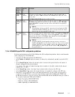
The following table summarizes the various communication break scenarios and provides a description of how
the output channels initialize back from the user-defined values.
Scenario
Output channel re-initialization description
•
Profibus device is disconnected from the network.
•
Profibus device has a power break condition and the
output channels are in an unpowered state.
The output channels are initialized back from the user-defined
values only after the connection breakout time timer has
exceeded.
FTE is removed
If the
Hold On Failure
parameter is not selected, the channels
are initialized back from the user-defined values immediately.
The channels do not wait for the connection breakout time
timer.
7 DEVICE SUPPORT BLOCK (DSB)
152
www.honeywell.com
Содержание Experion PKS
Страница 1: ...Experion PKS PROFIBUS Gateway Module User s Guide EPDOC XX88 en 431E June 2018 Release 431 ...
Страница 8: ...CONTENTS 8 www honeywell com ...
Страница 10: ...1 ABOUT THIS GUIDE 10 www honeywell com ...
Страница 32: ...4 PROFIBUS GATEWAY MODULE PGM INSTALLATION 32 www honeywell com ...
Страница 58: ...5 PROFIBUS GATEWAY MODULE PGM BLOCK 58 www honeywell com ...
Страница 69: ...6 PROTOCOL BLOCK 69 ...
Страница 103: ...5 Click OK 6 PROTOCOL BLOCK 103 ...
Страница 109: ...You can modify the following value from the Protocol Main tab detail display Alarming Enabled 6 PROTOCOL BLOCK 109 ...
Страница 110: ...6 PROTOCOL BLOCK 110 www honeywell com ...
Страница 181: ...7 20 3 Detail display tab Main tab Figure 4 Detail Display of Main tab 7 DEVICE SUPPORT BLOCK DSB 181 ...
Страница 182: ...Slave Status tab Figure 5 Detail Display of Slave Status tab 7 DEVICE SUPPORT BLOCK DSB 182 www honeywell com ...
Страница 183: ...PDC Details tab Figure 6 Detail Display of PDC Details tab 7 DEVICE SUPPORT BLOCK DSB 183 ...
Страница 184: ...DPV1 Details tab Figure 7 Detail Display of DPV1 Details tab 7 DEVICE SUPPORT BLOCK DSB 184 www honeywell com ...
Страница 185: ...Config Details tab Figure 8 Detail Display of Config Details tab 7 DEVICE SUPPORT BLOCK DSB 185 ...
Страница 186: ...7 DEVICE SUPPORT BLOCK DSB 186 www honeywell com ...
Страница 229: ...For a digital channel the detail display appears as follows 9 PROFIBUS I O MODULE PIOMB FUNCTION BLOCK 229 ...
Страница 231: ...9 PROFIBUS I O MODULE PIOMB FUNCTION BLOCK 231 ...
Страница 232: ...9 PROFIBUS I O MODULE PIOMB FUNCTION BLOCK 232 www honeywell com ...
Страница 236: ...10 PROFIBUS GATEWAY MODULE PGM CONFIGURATION EXAMPLE 236 www honeywell com ...
Страница 264: ...13 PROFIBUS GATEWAY MODULE PGM TROUBLESHOOTING 264 www honeywell com ...