Honeywell Enraf Скачать руководство пользователя страница 1

Honeywell Enraf  

SVP Controller Operation Manual

FOR ALL PROVERS EQUIPPED WITH  

SVP CONTROLLER

Содержание Enraf

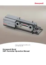
Страница 1: ...Honeywell Enraf SVP Controller Operation Manual FOR ALL PROVERS EQUIPPED WITH SVP CONTROLLER ...

Страница 2: ... HONEYWELL ENRAF SVP CONTROLLER OPERATION MANUAL FOR ALL PROVERS EQUIPPED WITH SVP CONTROLLER 3rd Edition Released March 2016 ...

Страница 3: ...al Power up 2 1 2 2 Navigating the SVP Controller Menus Using the LAD 2 1 2 2 1 Text Conventions 2 1 2 2 2 General 2 2 2 2 3 Commissioning 2 2 2 3 Menus and Navigation 2 3 2 3 1 General 2 3 2 3 1 1 Key benefits 2 3 2 3 2 Main Menu 2 3 2 3 3 Screen Input Fields 2 4 2 3 3 1 Text Input Screen 2 4 2 3 3 2 Numeric Input Screen 2 4 2 3 3 3 Enumeration Input Screen 2 5 2 3 3 4 Status Bar 2 5 2 3 4 Menu S...

Страница 4: ... 2 17 2 3 9 3 Alarm Logs 2 17 2 3 10 Diagnostics 2 18 2 3 11 Transfer 2 20 2 3 12 LAD Settings 2 21 CHAPTER 3 Operations 3 1 3 1 Operating Instructions 3 1 3 2 Meter Calibration 3 1 3 3 Prover Test 3 2 3 4 Prover Calibration 3 3 CHAPTER 4 Calibration 4 1 4 1 General 4 1 4 2 Static Leak Detection 4 1 4 3 Volume Water Draw 4 4 4 4 Gravimetric Water Draw 4 12 4 5 Calculations 4 19 CHAPTER 5 Troublesh...

Страница 5: ... Box 1 3 Figure 1 4 SVP Controller Box with LAD 1 3 Figure 2 1 The Local Access Device LAD and its system overview 2 2 Figure 2 2 Main Menu 2 3 Figure 2 3 Text Input Screen 2 4 Figure 2 4 Numeric Input Screen 2 4 Figure 2 5 Enumeration Input Screen 2 5 Figure 2 6 Status Bar 2 5 Figure 2 7 Menu Structure 2 6 Figure 2 8 Device Locking Menu 2 7 Figure 2 9 Password Input Screen 2 7 Figure 2 10 Configu...

Страница 6: ...or inserted in drive end plate 4 3 Figure 4 4 Static Leak Detection set up overview 4 3 Figure 4 5 Recommendation for seal change 4 4 Figure 4 6 Water Draw Kit 4 5 Figure 4 7 Water Draw Plumbing Diagram 4 10 Figure 6 1 Wiring Diagram 1 Phase 6 1 Figure 6 2 Wiring Diagram Dc 6 2 Figure 6 3 Wiring Diagram 3 Phase 6 3 LIST OF TABLES Table 1 Volumetric Water Draw Data Sheet 4 11 Table 2 Gravimetric Wa...

Страница 7: ...d even upgrading of firmware in the field The following warnings apply to all components of the SVP Warning Only use the instrument for its intended purpose EC declaration of conformity Refer to the EC declaration of conformity and ATEX certificate s shipped with the instrument Installation The mechanical and electrical installation shall only be carried out by trained personnel with knowledge of ...

Страница 8: ...wired No unauthorized changes are allowed as these would invalidate the approval The LAD and the SVP Controller are intrinsically safe devices and as such may only be connected to devices with compatible intrinsically safe parameters Intrinsically safe cabling may only be connected to the outside 5 pin socket of the SVP Controller Connection of non intrinsically safe signals will invalidate the ap...

Страница 9: ...nsure that the unit is fully depressurized and drained prior to disassembly or service Commissioning The commissioning of the instrument shall be conducted by qualified engineers trained by Honeywell Enraf and with knowledge of the local and national requirements for electrical equipment in potentially explosive atmospheres Operation After commissioning the Honeywell Enraf SVP and its associated S...

Страница 10: ...ery Directive Honeywell Enraf declared 97 23 EC Pressure Equipment Directive 60330 2009 CE HOU DNV Environmental conditions Ambient pressure atmospheric Relative humidity 5 95 Ingress Protection IP56 IP rating Ambient temperature ATEX Approval Standard Temperature 20 C to 40 C 4 F to 104 F Extended Temperature Options As broad as 40 C to 40 C 40 F to 104 F or 20 C to 60 C 4 F to 140 F CSA Approval...

Страница 11: ...provals ATEX II 2 G Ex d ia IIB T6 Gb IECEx Ex d ia IIB T6 Gb Certificates Approval Certificate number ATEX 12ATEX0101 X IECEx DEK 12 0021X CSA 11 2370409 Additional information specific to the Fusion4 LAD Approvals II 2 G Ex ia IIB T4 Gb Ex ia IIB T4 Gb Certificates Approval Certificate number ATEX KEMA 10ATEX0152 IECEx IECEx KEM 10 0070 CSA 11 2395571 ...

Страница 12: ...The Honeywell Enraf Prover Series xii SVP Controller Operation Manual Part No 44200004 Revision 2 Intentionally left blank ...

Страница 13: ...double chronometry function For brands not detailed consult Honeywell Enraf and the flow computer manufacturer If equipped with CONDAT or Prove It prover control systems refer to the operators manual for instructions for installation and operation The Honeywell Enraf small volume prover must be correctly earth grounded prior to electrical service connection 1 1 1 Field wiring The installation of t...

Страница 14: ...on 2 CUSTOMER CONNECTION BOX POWER BOX SVP ENCLOSURE Figure 1 1 Electrical Enclosures 1 1 3 1 Customer Connection Box The picture below shows the Customer Connection Box where you can connect your flow computer and other signals to the SVP Figure 1 2 Customer Connection Box ...

Страница 15: ...icture below shows the Power Box with two separate power connections one for the motor which generates electrical noise during operation and one for clean or instrument power Figure 1 3 Power Box 1 1 3 3 SVP Controller Box Connection of the LAD is as shown below Figure 1 4 SVP Controller Box with LAD ...

Страница 16: ...Installation 1 4 SVP Controller Operation Manual Part No 44200004 Revision 2 Intentionally left blank ...

Страница 17: ...example of a Prover Status screen is shown below Prover Status Meter Calibration Piston Parked Position Motor Idle Error Status No Error Cycle 776 Stop Time 10 31 12 11 29 32 AM Sweep Time 00 00 01 102 Press OK to enter menu Stop 2 2 Navigating the SVP Controller Menus Using the LAD Pressing the OK button on the Local Access Device LAD will result in the Main Menu screen being displayed on the SVP...

Страница 18: ... resetting and calibration The device facilitates two way data communications between the SVP Controller and the LAD allowing the rapid transfer of transaction data configuration files and calibration records and even firmware upgrading while in the field Figure 2 1 The Local Access Device LAD and its system overview 2 2 3 Commissioning The LAD is used to commission the SVP Controller by configuri...

Страница 19: ...ily understandable colored icons for the Main Menu and logically structured sub menus 2 3 1 1 Key benefits Clean intuitive and informative user interface No need to memorize parameter codes enumeration value Diagnostic screens Record based approach to transactions and calibrations make re use possible Interoperable with the Local Access Device LAD Provides a graphical user interface to the LAD 2 3...

Страница 20: ...rt No 44200004 Revision 2 2 3 3 Screen Input Fields 2 3 3 1 Text Input Screen Title bar Single line edit field Action message Numbers grouped Selected letter Letters grouped Figure 2 3 Text Input Screen 2 3 3 2 Numeric Input Screen Figure 2 4 Numeric Input Screen ...

Страница 21: ... Bar Figure 2 6 Status Bar Always visible on all screens Contains the following information Context specific information directions to user Status of the transactions e g Idle Running Error Device Locking Icon 2 3 4 Menu Structure For a high level overview of the entities and parameters see the following diagram Figure 2 7 For a detailed view of all menu items see the individual section Continued ...

Страница 22: ...Controller Information 2 6 SVP Controller Operation Manual Part No 44200004 Revision 2 Figure 2 7 Menu Structure Continued from previous page ...

Страница 23: ...the status bar in the bottom right corner padlock as seen in the following screen Figure 2 8 Device Locking Menu To lock the device the user must enter a password Figure 2 9 Password Input Screen To unlock the controller the user must enter the password as entered during the locking of the controller The password will be stored in non volatile memory Note that the locking feature is not infallible...

Страница 24: ... at the factory for the specific model of your prover When the device is locked the following configuration parameters cannot be changed via the LAD menu until the user unlocks the controller again Device 1 Identification Site Name Device Name 2 Units Units of volume 3 Display Display brightness Display Contrast Session time out value 4 Time Date display format Time display format Date Time 5 Moto...

Страница 25: ... Enter Average Volume and Abort Calibration 2 Navigate and see System Info 3 Navigate to Logs and see and retrieve Transaction Calibration and Alarm logs 4 Retrieve configuration path is Transfer Configuration Retrieve Configuration 5 Navigate and view Diagnostics Dashboard menu and activate or deactivate alarm output 6 Navigate and view storage info path is Diagnostics Storage Info 7 Navigate to ...

Страница 26: ... you can access the device configuration parameters The diagram below Figure 2 11 allows you to locate all of the configuration parameters Always the current device configuration values are shown All configuration values are edited one at a time in type specific data entry window Figure 2 11 Configuration Menu Tree ...

Страница 27: ...gineering units for volume Liter Cubic meter Cubic centimeter Cubic decimeter US Gallons UK Gallons Barrel L m3 cm3 dm3 US gal UK gal bbls 2 3 6 2 3 Display Entity Description Value range Display brightness With this entity the user can select the brightness of the display The brightness is controlled by the backlight of the display 0 low 100 high Display contrast With this entity the user can sel...

Страница 28: ...thout consulting Honeywell Enraf experts or damage to the prover may occur Entity Description Value range Motor switch timeout Configurable time interval by which piston puller must have reached motor stop switch before detection of a motor timeout error Covers retraction of piston from parked position to motor stop switch Units are in seconds Configurable range is from 5 seconds to 120 seconds fa...

Страница 29: ... Relay Output The Alarm Relay Output can be configured to be Energized normally closed or De energized normally open 2 3 6 4 Alarms The following alarm entity applies to Service Due Reminder and Machine Fault Entity Description Value range Alarm action With this entity the user can configure the alarm behavior in case this particular alarm will occur Disabled The alarm is ignored Display Alarm sho...

Страница 30: ... showing important information about The Device SVP Controller The individual boards HMI SVP and Option The firmware versions Figure 2 13 System Information Within this screen identification information is shown of the following device components Device serial number Production date Serial number of each FlexConn board Hardware version of each FlexConn board Application firmware version of each Fl...

Страница 31: ...roller Operation Manual 2 15 FlexConn stack firmware version of each FlexConn board Build information of the FlexConn stack firmware of each FlexConn board The menu tree below shows how the information menus are accessed Figure 2 14 System Information Menu Tree ...

Страница 32: ...ions over time Alarm Log a chronological list on when alarms occurred and what type of alarms they were Figure 2 15 Logs The log memory will be a rolling memory file with the oldest data being overwritten first when the memory is full Note that the log will be simply overwritten without issuing a warning message Figure 2 16 Logs Menu Tree 2 3 9 1 Transaction Logs The transaction log will contain t...

Страница 33: ...ction can be viewed by going to that transaction and pressing OK After every prover run cycle in prover calibration mode the following parameters will be logged after completing the prover run The calibration log contains the following information Date and time Sweep time in seconds Average volume Repeatability There are no units displayed for the average volume as they will be known by the user a...

Страница 34: ...est mode Figure 2 17 Diagnostics Within this screen the user can view the diagnostics about the following subjects Overview of all I O Dashboard Overview of system health Overview of all active alarms Overview of device tasks such as clearing tasks clearing alarms and running prover test task Overview of available memory storage space for data logs and total number of available logs The diagram be...

Страница 35: ...Controller Information Part No 44200004 Revision 2 SVP Controller Operation Manual 2 19 Figure 2 18 Diagnostics Menu Tree ...

Страница 36: ...e LAD is connected Via this user s interface the following type of records can be transferred between the SVP Controller and the LAD Transaction records Configurations Events logs alarms Calibration records Figure 2 19 Transfer The diagram below shows all of the information available to you Figure 2 20 Transfer Menu Tree ...

Страница 37: ...y when the LAD is connected This is the user interface to the LAD specific functionality Firmware download to the SVP Controller and the LAD Management of the LAD s stored records Format SD card Figure 2 21 LAD Settings The diagram below shows all of the information available to you Figure 2 22 LAD Settings Menu Tree ...

Страница 38: ...Controller Information 2 22 SVP Controller Operation Manual Part No 44200004 Revision 2 Intentionally left blank ...

Страница 39: ...g computer manual for procedures for performing meter proving runs 6 After meter proving runs have been completed open process diverter valve and slowly close the prover connection valves If you have the optional third optical switch installed on your prover refer to Chapter 2 section 2 3 6 2 6 for Sensor Pair configuration prior to operating your prover in any of the following three modes of oper...

Страница 40: ...ntroller screen At the end of the proving run the sweep time cycle count and the stop time will be updated If any errors occur during the proving run the error will be reported on the screen and will need to be cleared via the LAD Main menu Diagnostics Dashboard Alarm Clear see Chapter 5 Troubleshooting 3 3 Prover Test The Prover Test mode can be useful to become familiar with your prover and to v...

Страница 41: ...ed by a Flow Computer See Chapter 5 Troubleshooting if an error status is indicated To exit this operating mode use the LAD to navigate to Main Menu Diagnostics Prover Service Test Exit Prover Test Prover Status Prover Test Piston Parked Position Motor Idle Error Status No Error Cycle 787 Stop Time 10 31 12 11 39 32 AM Sweep Time 00 00 01 020 Press OK to enter menu Stop 3 4 Prover Calibration The ...

Страница 42: ...Operations 3 4 SVP Controller Operation Manual Part No 44200004 Revision 2 Intentionally left blank ...

Страница 43: ... 9 4 is the API standard used for the density determination of water The displaced volume has been calibrated as described in the MPMS API chapters 4 2 4 9 and 12 2 4 The Honeywell Enraf small volume prover base volume has been determined at the factory Recalibration is recommended either at 1 year intervals or as determined by the authorities and parties responsible for the measurement Recalibrat...

Страница 44: ...ing computer initiate a proving run to pull the piston upstream 8 Remove the plug from the drive cover end panel 9 Install the differential pressure creator 2 in the threaded hole provided in the drive system end plate and hand tighten refer to Figure 4 3 10 Rotate the adjustment screw 3 Figure 4 4 clockwise to push the plunger out to apply force to the piston shaft and create a differential press...

Страница 45: ...d be replaced Refer to Figure 4 5 Figure 4 1 Static Leak Detection Set up Figure 4 2 Gauge with HI LOW markings Figure 4 3 Differential pressure creator inserted in drive end plate FLOW Enraf HIGH PRESSURE 3 LOW PRESSURE ADJUSTMENT SCREW 2 DIFFERENTIAL PRESSURE CREATOR DIFFERENTIAL PRESSURE GUAGE 1 Figure 4 4 Static Leak Detection set up overview ...

Страница 46: ...easure is smaller than the prover volume there must be at least two test measures as the flow during water draws should be continuous for the greatest precision Example For a 20 gallon prover uses a single 76 L 20 gal test measure 4 Certified high resolution pressure gauge 0 690 kPag 0 100 psig psig 5 Three traceable thermometers with 0 1 C 0 2 F degree graduations for thermometer reference positi...

Страница 47: ...INCLUDED IN WATER DRAW KIT 1 2 SS BRAIDED HOSE CONNECT TO PROVER DOWNSTREAM SIDE CUSTOMER CONNECTION ENCLOSURE SOLENOID VALVE CONNECTION AND POWER SUPPLY TUBING TO WASTEWATER CATCH CONTAINER TUBING TO TEST MEASURE Description Terminal Number Wire Color Water Draw SV1 1 Red Water Draw Cable Water Draw SV2 2 White Water Draw Cable Water Draw Common 3 Black Water Draw Cable Customer Connection Enclos...

Страница 48: ... Figure 4 7 and install Honeywell Enraf available water draw kit see Figure 4 6 Install certified thermometers and certified pressure gauge even if the prover is equipped with P T transmitters If using Honeywell Enraf Water Draw P T kit remove the plug in the wafer spacer and connect the pressure gauge P1 to the opening see Figure 4 7 for reference The thermometer used to monitor prover fluid temp...

Страница 49: ...Enter Average Volume Abort Calibration Press OK to choose Stop 10 Enter the prover calibration mode using Enter Calibration Mode submenu Notification to user after selecting Enter Calibration Mode will show up on the SVP Controller screen see below Please note that permissive signal from the flow computer will be ignored while in prover calibration mode Entering Calibration Mode Pressing OK will e...

Страница 50: ... prover pressure Pp at P1 while only the water draw valve is open SV1 Valves V5 and V6 must be closed while recording this pressure which is the pressure at the start and the end of volume switching 15 Record temperature Td at T2 which is the detector temperature by opening the drive cover and placing the thermometer midway between volume switches which is the location of the switch bar temperatur...

Страница 51: ...After the Average Volume has been entered and confirmed the following screen is displayed to enter the Repeatability in percent The entered average volume and the repeatability values will be stored in the log with a timestamp of the entry After selecting Enter Average Volume following screen appears Enter Repeatability 0 00200 7 8 9 Backspace 4 5 6 Confirm 1 2 3 0 Enter value Stop Selecting Abort...

Страница 52: ...rating mode of the prover will be saved in NVM so that the mode will be restored if power is turned off while in Prover Calibration mode To exit calibration mode navigate to the Exit Calibration Mode menu and press OK A copy of Table 1 can be used to enter water draw data V2 V3 T1 P1 VENT VENT V6 SV1 SV2 V5 WATER SUPPLY S S Tp Pp T2 WASTEWATER CATCH CONTAINER FLOW TEST MEASURE SVP CONTROLLER Td V4...

Страница 53: ...be E Flow Tube Inside Diameter inches ID Flow Tube Wall Thickness inches WT Fill 1 Fill 2 Fill 3 Fill 4 Fill 5 Fill Time minutes Flow Rate Nominal Volume Fill Time Temperature Prover Tp Temperature Detector Td Prover Pressure Pp Scale Reading on Volume Measure SR Volume of Water adjusted for SR BMVa Test Measure Temperature Ttm Correction for Temp Differential Ctdw Effect of Temp on Test Measure C...

Страница 54: ...kPag 0 100 psig 7 Three traceable thermometers with 0 1 C 0 2 F graduations for thermometer reference positions see Figure 4 7 8 Water draw data sheet Table 2 9 Water overboard container volume to be at least as large as test measure Note Honeywell Enraf Water Draw P T kit or equivalent assembly eases installation of water draw prover instrumentation The Honeywell Enraf Water Draw P T kit consists...

Страница 55: ...well located on the downstream side of the flow tube see Figure 4 7 for reference The thermometer used to monitor switch bar temperature T2 is supposed to be installed on top of the switch bar close to the center line between two optical switches see Figure 4 7 for reference The thermometer T4 is supposed to be used to monitor ambient temperature see Figure 4 7 for reference Have available Table 2...

Страница 56: ...r screen see below Please note that permissive signal from the flow computer will be ignored while in prover calibration mode Entering Calibration Mode Pressing OK will enter the controller into Calibration Mode The bypass valve will open immediately To perform calibration run select Run Calibration from next menu Press OK to proceed Stop 13 Bypass valve SV2 will be turned ON immediately after ent...

Страница 57: ...o the Test Measure 17 Record the prover pressure Pp at P1 while only the water draw valve is open SV1 Valves V5 and V6 must be closed while recording this pressure which is the pressure at the start and the end of volume switching Note The draw can be sped up by opening valve V6 after the valves have switched to flowing into the Test Measure located on the scale and the prover pressure Pp is recor...

Страница 58: ...to enter water draw data An Excel readable file is available from Honeywell Enraf which will calculate the corrected prover volume using the gravimetric method After selecting Enter Average Volume following screen appears Enter Average Volume 5 37000 7 8 9 Backspace 4 5 6 Confirm 1 2 3 0 Enter value Stop 27 Enter the average calibration volume calculated in the previous step by selecting the Enter...

Страница 59: ...he Prover is in sweep mode with the piston moving downstream no action will be taken for upstream and downstream sensor inputs Calibration log entry will not be made In calibration mode alarms will be generated as per the configuration and the run permissive signal from the flow computer or the run prover test signal will be ignored The operating mode of the prover will be saved in NVM so that the...

Страница 60: ...cient Gl Modulus of Elasticity of flow tube E Flow Tube Inside Diameter inches ID Flow Tube Wall Thickness inches WT Fill 1 Fill 2 Fill 3 Fill 4 Fill 5 Fill Time minutes Temperature Air Ta Temperature Prover Tp Temperature Detector Td Prover Pressure Pp Water Electrical Conductivity Total Mass of Water Ww Density of Air ρA Calculated Density of Water ρw Correction of Air Buoyancy of Weighing CBW C...

Страница 61: ... API 12 2 1 11 2 1 Gl Linear coefficient of expansion for detector API 12 2 1 11 2 1 Gc Coefficient of expansion for the test measure from calibration certificate E Modulus of elasticity for flow tube material from API 12 2 Appendix A WT Thickness of flow tube wall inches ID Diameter of flow tube inches Calculate BMVa Base Measured Volume adjusted for scale reading BMV SR CTDW Correction for prove...

Страница 62: ...ensity of test weights gm cc Ga Area coefficient of expansion for flow tube API 12 2 4 Gl Linear coefficient of expansion for detector API 12 2 4 E Modulus of elasticity for flow tube material API 12 2 Appendix A WT Thickness of flow tube wall inches ID Diameter of flow tube inches Calculate Calculation of Air Density in USC Units ρA 0 001223068 1 0 032 x h 1000 519 67 Tf 459 67 Where ρA is the de...

Страница 63: ...s 3 596458E 12 C 5 Note Above provided equation provide density correlations for density of distilled water If the water to be used in the Gravimetric Method does not meet the criteria of distilled or deionized water water from an approved public water potable supply may be used in this procedure However the conductivity must not exceed 50μs If the conductivity of the test water is between 50μs an...

Страница 64: ...Calibration 4 22 SVP Controller Operation Manual Part No 44200004 Revision 2 Intentionally left blank ...

Страница 65: ...ng sequence was not completed successfully In order to clear the error check if the optical switches are functioning using the dashboard function see 5 3 1 motor stop switch is functioning using the dashboard function see 5 3 1 the ramp located on the guide block is adjusted properly the flag located on the guide block is correctly positioned 5 2 2 Motor time out This error message means that the ...

Страница 66: ...or service as determined by the entry at Main Menu Configuration Alarms Service Due Reminder 5 3 Diagnostics There are several screens inside the Main Menu Diagnostics menu to aid in troubleshooting 5 3 1 Dashboard The dashboard screen allows you to verify the status of the inputs and outputs of the SVP Controller Each output function can be tested by selecting it and activating it Dashboard Down ...

Страница 67: ... small volume prover is not properly connected Check connections and integrity of cables see Section 6 and flow computer manual Above checks do not resolve problem See Section 5 for troubleshooting controller optical switches and motor stop switch Honeywell SVP Controller is not in Meter Calibration Mode Exit Prover Test Mode Section 3 3 or Prover Calibration Mode Section 4 3 and 4 4 Unsteady or a...

Страница 68: ...Troubleshooting 5 4 SVP Controller Operation Manual Part No 44200004 Revision 2 Intentionally left blank ...

Страница 69: ...section contains various electrical schematics and drawings for the Honeywell Enraf small volume prover If there are electrical questions not addressed by these figures contact your nearest Honeywell Enraf representative or the factory directly 6 1 Schematics for prover wiring Figure 6 1 Wiring Diagram 1 Phase ...

Страница 70: ...Electrical Schematics Drawings 6 2 SVP Controller Operation Manual Part No 44200004 Revision 2 Figure 6 2 Wiring Diagram DC ...

Страница 71: ...Electrical Schematics Drawings Part No 44200004 Revision 2 SVP Controller Operation Manual 6 3 Figure 6 3 Wiring Diagram 3 Phase ...

Страница 72: ...cts to the prover detector input of the E Combo Module The prover detector input on the Omni is usually Pin 7 Connect Volume Pulse terminal 17 of the Customer Connection Box to common on the rear of the Omni This is usually Pin 10 which is tied to common on the power supply The prover Run permissive command terminal 13 of the Customer Connection Box connects to any Omni Digital I O point That poin...

Страница 73: ...ructions Note The pin numbers listed adjacent to the colors signify the pin locations on the CIUs Control connector Within the Customer Connection Box the terminals 12 and 15 are provided to securely land customer provided voltage or ground leads as needed For the CIU the ground earth reference is Black Customer Connection Box Terminal 17 and the nominal 15VDC supply is Red Customer Connection Box...

Страница 74: ...ulses After the run is complete the CIU will return to idle conditions until the next run command is sent 6 2 3 Daniels Actual terminal locations for the Daniel flow computer is dependent upon the application software being used in the Daniel flow computer See the appropriate Daniel manual and software information for more information Warning Due to scan speed the 2500 has limitations in flow rate...

Страница 75: ...Flow Computer 15 Volume pulse 16 Volume pulse 17 1 5Kȍ Resistors not labeled can be 1 to 5 K depending on Supply strength 6 3 After Sales Support Honeywell GTS Global Technical Services support the Honeywell Enraf provers globally All after sales support enquiries should be channeled to GTS in the first instance Honeywell Enraf have strategically positioned global service partners in USA Europe As...

Страница 76: ...oneywell Enraf can offer Commissioning start up including replacement of the transit seals A periodic maintenance service which normally consists of changing seals checking alignment of drive end and changing optical switches and a differential pressure test to check for seal leakage Recommended annually Water draw is Recommended every 2 years Small Volume Prover Inspection and Refurbishment Proje...

Страница 77: ...e Yes many Honeywell Enraf provers are installed in Standby Mode but it is recommended to consider the more durable elastomer option when operating a prover in this way This is the best practice for fluids that are at temperatures higher or lower than ambient continuous to allow for faster warm up time How much pressure drop does the Honeywell Enraf Flow Prover Have Under normal operating conditio...

Страница 78: ...Honeywell Enraf Americas Inc 2000 Northfield Court Roswell GA 30076 4908 U S A Tel 770 475 1900 Fax 770 475 1717 www honeywellprocess com 44200004 March 2016 2016 Honeywell International Inc ...

Отзывы: