W
innox · Edition 12.20
EN-4
Mounting pattern
3
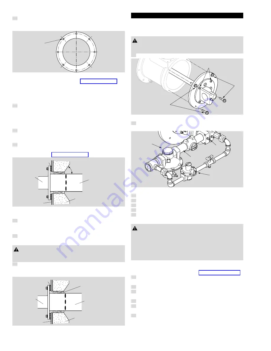
Attach eight mounting bolts to the chamber wall. Position these
bolts to match the clearance holes (
C
) on the burner mounting
flange.
C
Chamber mounting pattern
➔
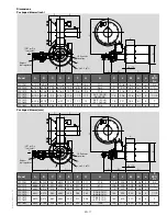
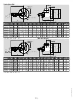
More information can be found here: page 17 (Dimensions).
tube shrouding considerations
➔
Applications in which there is process air flow perpendicular to and
across the Winnox combustor greater than 1000 ft/min (5 m/s) may
cause flame instability and/or high production of CO emissions.
4
In these applications a shroud may be required to shield the
combustor. Contact Eclipse for more information.
Chamber wall
➔
Make sure the chamber wall
B
is strong enough to support the
weight of the burner
C
.
5
If necessary, reinforce the mounting area. See figure "Chamber
wall".
note:
The slots in the combustor must not be covered with insulation.
6
If necessary, taper the chamber insulation at a minimum of 45°
to provide clearance for the combustor slots. Slot dimensions
can be found here: page 17 (Dimensions).
C
B
A
Combustor
Slots
Chamber
Insulation
Min. 45°
Chamber wall
Burner mounting
7
Mount the burner to the chamber wall using eight (8) customer
supplied nuts and lock washers.
Alloy combustion tube
8
Be sure gasket
A
is installed between burner
C
and chamber wall
B
. See figure "Alloy combustion tube".
CAUtIon
– Placing insulation over combustor slots will impede burner
performance and decrease combustor life.
9
Pack fiber insulation around the tube to a depth not beyond the
combustor slot position, as shown in figure "Alloy combustion
tube".
C
B
A
Combustor
Fiber
insulation
Slots
Chamber
Insulation
Alloy combustion tube
GAs PIPInG
Burner piping
➔
The burner is factory assembled and shipped as ordered.
note:
If you have to realign the pipes, please observe the following!
CAUtIon
– Do not attempt to redirect piping by removing the inner circle
bolts
e
. Internal burner parts will be damaged.
1
Remove the outer
A
four bolts only.
E
A
A
Redirect piping
2
Rotate the rear cover and replace bolts.
When reassembling, ensure the following.
B
C
D
F
Burner piping
3
The ratio regulator spring column
B
is pointing down.
4
The bypass regulator spring column is pointing up
F
.
5
The arrow on the ratio regulator points in the direction of gas flow.
6
Integral fuel orifice and o-rings
C
are reinstalled.
7
The same straight run of pipe
D
remains between the ratio reg-
ulator and the burner.
CAUtIon
– Do not alter the bypass regulator. The NFPA requires that the
bypass regulator
F
be appropriately vented and protected.
– For applications in which the Winnox is operating indoors, a
vent limiting device is installed in the bypass regulator.
– For applications in which the Winnox is operating outdoors, an
insect/rain protector is installed in the bypass regulator.
supply piping
➔
Inlet pressure to the ratio regulator must stay within specified limits.
More information can be found here: page 10 (Technical data).
8
Locate the valve train close to the burner. The gas must reach
the burner during the fixed trial for ignition period.
9
Sufficiently size the shut off valve in the valve train.
10
Make sure piping is large enough to accommodate flow required
to meet burner input.
11
Minimize piping elbows.
12
Install fuel flow measurement device
A
upstream from the burner
inlet.
13
If necessary to maintain inlet pressures to the burner (see datasheet
for your burner), install a gas pressure regulator
B
upstream of
the burner inlet and downstream of the valve train and fuel meas-
urement device
A
.


