background image

HONEYWELL 7000 SOLID STATE ALARM SYSTEM

69-1192—1

8

ON

ON

ON

ON

ON

ON

ON

ON

OFF OFF OFF

ON

ON

ON

ON

OFF OFF OFF OFF

ON

ON

ON

ON

ON

OFF OFF

ON

ON

OFF OFF

ON

ON

OFF

ON

OFF

ON

OFF OFF OFF

ON

OFF

ON

OFF

ON

1

2

3

4

5

6

7

8

9

10

11

1

2

3

4

1

2

3

4

S1

TB1

TB2

OFF

ON

S1

S1

SETS PEM ADDRESS #

S1

SHOWN SET FOR ADDRESS #1

MAXIMUM OF 11 PEMs ON A SYSTEM

PEM ADDRESS #

11

10

9

8

7

6

5

4

3

2

1

1

2

3

4

5

6

7

8

9

10

11

GND

P1

P2

P3

P4

GND

P5

P6

P7

P8–

P8+

NO

EOLR

NC

NO

EOLR

NC

ALL EOLR = 
3.3K

1/4W

5%

TYP WIRING: POINT 1-7

WIRING: POINT 8

GND

GND

+13.8 VDC

HBUS–

HBUS+

RELAY 1

TO
CONTROL 
PANEL

GOLDEN VALLEY, MINN.

RELAY 2

NO

NC

C

NO

NC

C

BLK

RED

GRN

YEL

M10902

RELAY:
CURRENT DRAIN 

 40 mA

CONTACT RATING:
  RESISTIVE
      2A @ 30 VDC
      0.4A @ 30 VAC
  INDUCTIVE
      1A @ 30 VDC
      0.2A @ 30 VAC

LABEL 2480341  REV B

PEM

SYSTEM 7000

SEE INSTALLATION MANUAL

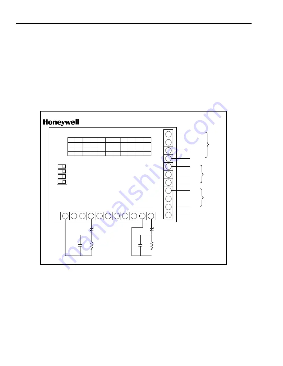
PEM Wiring

1.

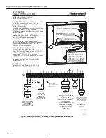
Use four-conductor AK4500A cable to connect the PEM
to other HBus devices.

2.

Connect the PEM wires to the control panel according
to the wiring diagram with the unit. See Fig. 6.

Each PEM has a unique, four digit, address. Fig. 6 lists the
PEM address number and switch settings. The Honeywell
7000 System can support up to 11 PEM.

RFEM Installation

The RFEM provides additional rf protection points for the
Honeywell 7000 System. Only one RFEM can be used per
system.

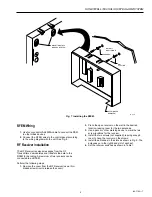
Mount the RFEM plastic box within 250 feet (76 meters) of
the control panel if using 22 AWG wire or 500 feet (152
meters) if using 18 AWG wire.

Remove the RFEM circuit board from the RFEM plastic box
(if installed) and use the RFEM plastic box to mark the
mounting screw locations on the wall or plywood. Use two
screws to mount the RFEM plastic box. Insert the RFEM
circuit board into the RFEM plastic box. See Fig. 7.

Fig. 6. PEM wiring diagram.

Содержание CommerCialPro 7000

Страница 1: ...ed to meet the demanding needs of homeowners FEATURES Can display up to 96 points of protection Eight hardwire zones built into the control panel Optional RF and hardwired expansion on Hbus Supports keypads with custom text displays Mode based operation for simple error free control Date and time stamped event log Up to 24 fully programmable outputs Contents Application 1 Features 1 Specifications...

Страница 2: ...Vdc Keypad 120 mA Point Expansion Module PEM 60 mA 120 mA when both relays are on RF Expansion Module RFEM 60 mA Ademco Receiver 50 mA Ademco Transmitters see individual Ademco specification sheet with each type of transmitter Battery Backup 7AH Minimum 28 AH Maximum at 12 to 13 8 Vdc Fuses One 2A AGA2 fuse F3 AC Digital Communicator Located on Control Panel Format Modem 2E Line Seizure Double Pol...

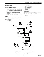
Страница 3: ...of the system Fig 1 and installation and hookup instructions for the following equipment 1 Control Panel a Enclosure b Circuit Board c Transformer 2 Point Expansion Module 3 RF Expansion Module 4 RF Receiver 5 RF Transmitter 6 Keypad Control Panel The control panel performs the main functions of the system The following can be found inside the control panel enclosure a Control Panel Circuit Board ...

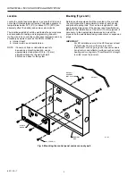
Страница 4: ...ched to the wall with wall anchors as a base for the system Mounting Fig 2 and 3 Determine what equipment will be mounted on the wall with the control panel box approximate location of each device and probable wiring runs This can be a rough sketch with approximate dimensions of the devices see Specifications Based on this information cut the 3 4 in 19 mm plywood if necessary to the appropriate di...

Страница 5: ...d Wiring The control panel circuit board is the central wiring point for most of the system Connections are available for a Loop wiring b Smoke detector wiring c Backup batteries d External bell horn e Ac connections f Earth ground g Telephone interface connection h HBus devices keypad PEM RFEM etc Wiring instructions for each of these connections or devices are provided in the appropriate section...

Страница 6: ...DETECTORS SMOKE DETECTOR COMPATIBILITY IDENTIFIER IS 7K8 P8 MAY BE WIRED FOR 2 WIRE FIRE OR 4 WIRE FIRE OR BURGLARY 2 WIRE FIRE IS SHOWN FOR 4 WIRE FIRE AND BURGLARY WIRING SEE INSTALLATION INSTRUCTIONS HBUS 1 HBUS 2 COM 3 13 8 VDC 4 P1 5 P2 6 COM 7 P3 8 P4 9 COM 10 P5 11 P6 12 COM 13 P7 14 P8 15 P8 16 AUX 17 HORN 18 COM 19 13 8 VDC 20 AC IN 21 AC IN 22 STANDBY BATTERY MINIMUM REQUIREMENTS 12 VDC ...

Страница 7: ...PPLIED PEM COVER REMOVED ANCHORS M10912 MOUNTING SLOTS ON BACK OF RFEM can support normally open NO or normally closed NC sensor contacts The PEM has eight hardwire point connections and two relay output connections Mount the PEM plastic box within 250 feet 76 meters of the control panel if using 22 AWG wire or 500 feet 152 meters if using 18 AWG wire Remove the PEM circuit board from the PEM plas...

Страница 8: ...41 REV B PEM SYSTEM 7000 SEE INSTALLATION MANUAL PEM Wiring 1 Use four conductor AK4500A cable to connect the PEM to other HBus devices 2 Connect the PEM wires to the control panel according to the wiring diagram with the unit See Fig 6 Each PEM has a unique four digit address Fig 6 lists the PEM address number and switch settings The Honeywell 7000 System can support up to 11 PEM RFEM Installatio...

Страница 9: ...lates and transfers the data to the RFEM for decoding A maximum of two receivers can be connected to an RFEM Perform the following steps 1 Remove the cover from the RF Receiver use a thin bladed screwdriver to release the cover 2 Place the open receiver on the wall in the desired location leaving room for the two antennas 3 Use a pencil or other marking device to mark the two screw locations for t...

Страница 10: ...8 AWG cable Do not route keypad wiring parallel to ac wiring or within 12 in of ac wiring NOTE A maximum of 11 keypads can be installed on one Honeywell 7000 System The control panel can supply power for up to four keypads Additional keypads must be powered by an external 12V power source with backup batteries A standard plastic base is provided To mount the keypad 1 Secure the base to the wall 2 ...

Страница 11: ... xxxx xxxxx xxxxx xxxxx xxxxx xxxxx 1 2 3 4 5 6 7 8 9 0 xxxxx xxxx xxxxx xxxxx xxxxx xxxxx xxxxx 1 2 3 4 5 6 7 8 9 0 xxxxx xxxx xxxxx xxxxx xxxxx xxxxx xxxxx 1 2 3 4 5 6 7 8 9 0 xxxxx xxxx xxxxx xxxxx xxxxx xxxxx xxxxx 1 2 3 4 5 6 7 8 9 0 xxxxx xxxx xxxxx xxxxx xxxxx xxxxx xxxxx 1 2 3 4 5 6 7 8 9 0 xxxxx xxxx xxxxx xxxxx xxxxx xxxxx xxxxx 1 2 3 4 5 6 7 8 9 0 M10893 120 OHM 120 OHM 120 OHM KEYPAD K...

Страница 12: ... 1000 feet 4 Each circuit must be terminate with a 3 3K ohm 1 4 watt EOLR provided 5 Make all connections according to the loop diagrams that follow 6 Program loops for type as well as NC or NO contact operation xxxxx xxxx xxxxx xxxxx xxxxx xxxxx xxxxx 1 2 3 4 5 6 7 8 9 0 xxxxx xxxx xxxxx xxxxx xxxxx xxxxx xxxxx 1 2 3 4 5 6 7 8 9 0 M10896 120 OHM KEYPAD KEYPAD xxxxx xxxx xxxxx xxxxx xxxxx xxxxx xx...

Страница 13: ...ignals a warning for time period 2 when violated and is ignored during the normal exit and entry delay periods Tamper A burglary circuit that is always on Violation of this point will be reported but the local audible alarm can be optioned to be silenced Police A burglary alarm that instantly alarms on cross or break when violated The audible alarm is selectable separately Fire A fire circuit that...

Страница 14: ...all exposed leads 6 Make sure that all wire is contained within the base of the smoke detector 7 Program a Special Mode with the name FIRE RESET to operate the fire reset relay from a programmable output Four Wire Circuit Reset Operation Fig 17 Reset four wire smoke detectors from the keypad by entering the disarm code and pressing the FIRE RESET mode numeric key The reset period is approximately ...

Страница 15: ...to three inches to get them away from multi path nulls Outputs Honeywell 7000 System supports two solid state outputs on the main control panel and two relay outputs on each PEM All but the HORN output are fully programmable for maintained or momentary operation They can be a activated by events Burglar Alarm Fire Alarm Equipment Alarm Police Alarm Medical Special Alarm System Ready On Watch Inter...

Страница 16: ... Fig 19 Transformer Installation The Honeywell 7000 System is powered by a 120 Vac to 24 Vac 50A plug in transformer Install the transformer as follows 1 Locate the control panel within 25 ft of a non switched power receptacle 2 Make sure that S1 the control panel power switch is off 3 Use UL listed two conductor twisted pair 18 AWG wire to connect the transformer to the AC IN connectors TB1 21 an...

Страница 17: ... function of the size of the system The formula used to calculate battery capacity is Normal current Amps x 24 hours Alarm current Amps x 1 15 hours 10 Capacity needed AH Divide the ampere hour result by seven to obtain the number of 7AH batteries needed for the system Table 8 gives current usage normal and alarm for the devices in the system Adding the normal and alarm currents of the system and ...

Страница 18: ...8AH of standby battery power Sample Configurations Table 9 lists sample configurations Any of these configurations can be downsized less modules or components and still meet the battery standby times for that configuration Installation per these guidelines will meet the California State Fire Marshal CFSM 24 hour battery backup requirement Earth Wire Grounding An earth ground can be a cold water pi...

Страница 19: ...teps will enable Programming Refer to Programming Instructions form 24510169 for details Setup NOTE The following procedure steps apply to local programming with a PC If remote programming Downloading a program from the CSC is applicable skip steps 2 and 3 complete steps 4 through 7 to enable remote programming The system will be ready for the CSC to call and the system will connect and the CSC pr...

Страница 20: ...answering machines FAX machines and local telephone company options 31 Enter the FIRE POLICE and SPECIAL Keypad point numbers 32 Enter Fire Audible Shutoff UL requires this to be set to 4 minutes or greater 33 Set Police Special and Tamper Audibles Silent or not silent 34 Set the Entry Delay times 0 to 255 seconds 35 Pick customer city 36 If necessary pick time zone Previous step should exclude ne...

Страница 21: ...n pressed will show all points that are not ready The up arrow key shows the points that are bypassed and the special protection points that are disarmed d Audible Feedback Each time you press any key an audible tone will sound to confirm successful entry of a digit or function e LED s Two LED s between arrow keys The LED next to the UP arrow when lit indicates that some Special Protection is turn...

Страница 22: ...and Trouble Indications on the Keypad 1 Entry Exit Delay Pulsed low tone one second ON 0 1 second OFF for the duration of the programmed Entry 1 or 2 or the Exit delay timer EXIT NOW is displayed on line 1 of the LCD Audible Increases in speed for the last 10 seconds Exit audible is silent for home occupancy modes 2 Burglary Alarm Continuous loud tone the point alarm description is displayed on li...

Страница 23: ...ugh 12 0 volts 11 Tamper Alarm Continuous loud tone displayed the same as any other burglary point This hardwire point is programmed as a 24 hour burglary zone External Siren is delayed 15 seconds 12 Transmitter Low Battery A tone will be heard between 8 AM and 8 PM This could be up to 12 hours after displaying the message The tone delay is to avoid annunciation during sleeping hours Each time the...

Страница 24: ...and password entered Table 11 Keypad LCD and LED response to system operation Emergency System Shutoff This procedure will completely disable your entire security system including the 24 hour protected points the display Keypads and outputs Use this procedure only as a last resort if 1 All efforts to turn off the audible alarms fail or 2 You cannot disarm the security portion of the system by any ...

Страница 25: ...ted twice within 8 seconds The Transmitter Point ID description will appear and the KEYPAD will annunciate a one second tone IMPORTANT Use only Ademco 5800 transmitters on the Honeywell 7000 System control panel 1 Customer Service Center CSC Test 1 Call the CSC to coordinate testing of the system 2 Reconnect the telephone cord from the Control Panel to the RJ 31X jack 3 Press the MODES key and arm...

Страница 26: ...85 amperes of alarm for 4 minutes for 24 hours of battery backup 7 Use ALARM SAF AP PS5BF 12 UL when auxiliary power is required What You See What is Wrong What You Should Do HOME NOT READY FORCE ARM These Points not ready 1 A protected point is open and or 2 A transmitter cover is open 1 Press the right arrow button to look at open points 2 Open and close the named door or window and leave it clo...

Страница 27: ...nges or modifications to the equipment unless authorized by the Installation Instructions or User s Manual Unauthorized changes or modifications could void the user s authority to operate the equipment This equipment complies with Part 68 of the FCC rules On the front cover of this equipment is a label that contains among other information the FCC registration number and ringer equivalence number ...

Страница 28: ...nd Building Control Honeywell Limited Honeywell Limitée 155 Gordon Baker Road North York Ontario M2H 3N7 Honeywell Latin American Region 480 Sawgrass Corporate Parkway Suite 200 Sunrise FL 33325 69 1192 1 G R Rev 9 98 Home and Building Control Honeywell Inc Honeywell Plaza P O Box 524 Minneapolis MN 55408 0524 Printed in U S A on recycled paper containing at least 10 post consumer paper fibers www...

Отзывы: