Honeywell
UND ERGROUND GAS REGULATION STATION
TYPE: COCON 26 DRA-LP/MP
Active - Slam
MAINTENANCE AND ASSEMBLY MANUAL
Assembly and maintenance documentation
Cocon 26 Active – Slam configuration
July
12,
2017
Rev
0
Страница 1: ...neywell UNDERGROUND GAS REGULATION STATION TYPE COCON 26 DRA LP MP Active Slam MAINTENANCE AND ASSEMBLY MANUAL Assembly and maintenance documentation Cocon 26 Active Slam configuration July 12 2017 Rev 0 ...
Страница 2: ... Assembly of Safety Unit S S V 16 2 8 Assembly of Regulator Pilot Safety Relief Valve and Measuring Units such as Vent and Pressure Relief Pipes 18 2 9 Assembly of Dust Filter 23 3 Inspection 25 3 1 Inspection of Gas Regulating Station and Safety Unit 25 3 2 Test Casing 26 3 3 Assembly of the Gas Regulating Station and Safety Unit on the Test Casing 27 3 4 Leakage Test 27 3 5 Setting of the Gas Re...
Страница 3: ...tation with auxiliary power from the inlet pressure Safety Shut off Device Safety Shut off Valve with monitor control Filter Material Felt Separation Rate 98 at particle size of 3 micron 0 003 mm Shut off Valves Inlet Ball Valve DN 50 ANSI300 Outlet Butterfly valve DN150 PN 16 or PN25 Mounting of Type Plates on the membrane cover under the pit cover on the regulator pilot on the monitor control an...
Страница 4: ... the following instructions when working Always wear protective goggles when assembling the unit Use the right tools to assemble the individual components Keep the parts mentioned in a chapter together and separate them from other parts mentioned in other chapters This way you will have sorted all parts for the assembly of a component part as described in a specific chapter Disassemble the parts o...
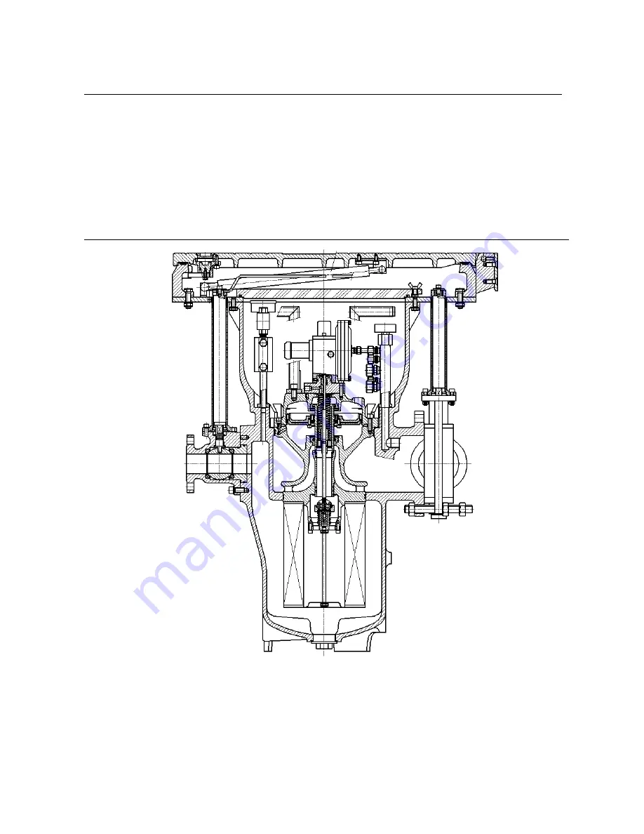
Страница 5: ...Maintenance manual Honeywell Maintenance and assembly manual underground gas pressure reducing station Type COCON26 DRA LP MP A S page 5 Diagram 02 01 ...
Страница 6: ...to the membrane holder with four hex socket head screws 46 Put this part aside Slide the guiding holder 47 over the guide valve rod 23 Secure the guiding holder to the guide valve rod with a lock ring 52 The frame on the outer diameter of the control valve 20 separates the control valve into a short and a long end Slide the largest diameter of the guide valve rod 23 into the long end of the contro...
Страница 7: ...04003131980 12 1 Membrane 8104004106720 20 1 Control Valve 8104003131970 23 1 Guide Valve Rod 8104004100520 43 1 Seal Ring 8401050502136 44 1 Membrane Disc 8104003131990 46 4 Hex Socket Head Screw 8251050060016 47 1 Guiding Holder 8104004100530 51 1 Lock Ring 8236050040001 52 1 Lock Ring 8236000015001 64 4 Screw 8251110060016 65 1 Disc 8104004131960 We recommend to have on stock the with marked pa...
Страница 8: ...ainer 30 into the safety shut off valve The seal ring is pressed between the safety shut off valve and retainer Secure the retainer onto the safety shut off valve with two hex socket head screws 28 and spring rings 29 Slide the retainer over the valve rod and against the sinus spring rings Press the safety shut off valve against the spring pressure of the sinus springs and place the seal ring 32 i...
Страница 9: ... 03 25 1 Valve Rod 8104004100230 27 2 Sinus Spring Rings 8503210653400 28 2 Hex Socket Head Screw 8207160040012 29 2 Spring Ring 8237020040001 30 1 Retainer 8104004150990 31 1 Seal Ring 8404037703222 32 1 Seal Ring 8404006002108 56 1 Safety Shut off Valve 8104004103880 58 1 Guiding 8104004100550 We recommend keeping the spare parts marked with ready for maintenance purposes Diagram 02 03 ...
Страница 10: ...ide 10 Place a seal ring 41 into the groove on the exterior Place the cover of the cartridge 40 with the concave side facing upwards Slide the valve guide onto the edge in the centre of the cartridge cover Close the valve guide with a lock ring 42 cover of the cartridge Turn over the cover of the cartridge Place the seal ring 3 into the groove on the top of the cover of the cartridge Put this part...
Страница 11: ...seat holder Secure the seal ring with a valve cup 60 Slide the diameter of the valve seat holder through the hole in the middle of the gas regulation casing The valve seat holder frame is located on the gas regulation casing Place the gas regulation casing to one side Secure the valve seat holder with a lock ring 55 at the lower end of the gas regulation casing Fasten the seal ring 71 in the groov...
Страница 12: ... Seal Ring 8401006101010 15 2 Seal Ring 8401253603274 24 1 Valve Seat Holder 8104003117480 41 1 Seal Ring 8401071102149 42 1 Lock Ring 8236050075001 50 1 Seal Ring 8404047203225 53 2 Seal Ring 8401044102132 54 1 Gas Regulation Casing 8104541126230 55 1 Lock Ring 8236000050001 60 1 Valve Cup 8104004117490 66 1 Valve Guide 8104004134710 71 1 Seal Ring 8401049236000 We recommend to have on stock the ...
Страница 13: ...n the cover of the cartridge Press the thicker membrane edge into the groove in the cover of the cartridge Lower the cover of the cartridge slowly onto the top of the gas regulation casing Slide the control valve through the valve guide 02 05 Pos 66 in the upper flange of the gas regulation casing 02 06 A spring pin centres the cover of the cartridge to the upper flange of the gas regulation casin...
Страница 14: ...Maintenance manual Honeywell Maintenance and assembly manual underground gas pressure reducing station Type COCON26 DRA LP MP A S page 14 Diagram 02 06 ...
Страница 15: ...al underground gas pressure reducing station Type COCON26 DRA LP MP A S page 15 PARTS LIST 02 06A No of Items belonging to diagram 02 06A 45 12 Hex Socket Head Screw 8251050100035 73 1 Locking Screw 6447200001000 74 1 Locking Screw 6447210001000 Diagram 02 06A ...
Страница 16: ...valve rod 23 against the shut off valve rod Place the connection piece 6 with the threaded hole facing upwards Place the seal ring 61 on the bottom of the chamber Place the pressure pin guide 8 with the largest hole facing upwards Place the seal ring 4 into the pressure pin guide 8 Place the seal rings 68 into the pressure pin guide 8 Close everything with lock rings 67 Screw the pressure pin guid...
Страница 17: ... 7 4 Hex Socket Head Screw 8251050120020 8 1 Pressure Pin Guide 8104004138340 9 1 Pressure Pin 8501114131660 33 4 Spring Ring 8237020060001 34 4 Hex Socket Head Screw 8207160060020 38 4 Hex Socket Head Screw 8251050080035 57 1 Pressure Pin 8501134106490 59 1 Pressure Pin Safety Unit 8104004100060 61 1 Seal Ring 8401023501021 67 1 Lock Ring 8251437012001 68 1 Ring 8104004138400 99 1 Monitor Control...
Страница 18: ...eve secures this cartridge The outlet pressure measuring sleeve is positioned on the low pressure side of the station An outlet pressure gauge 20 is mounted to the top side of the outlet pressure measuring sleeve 26 with a reduction sleeve 26 Place the seal rings 27 into the areas underneath the measuring sleeves NOTE Make sure that all connecting pieces are sufficiently greased with a gas resista...
Страница 19: ...onnection of the measuring sleeve Mount the other end of this pipe with an adjustable angle pipe fitting with a thread 5 in the floor connection of the safety relief valve AV LP MP Mount the adjustable angle fitting 12 in the side connection of the safety relief valve AV LP MP and connect the tube 35 with an adjustable angle fitting Secure the pipe to the connection on the cover of the cartridge w...
Страница 20: ... Pipe 15 1 Pipe Stainless Steel Pipe 20 1 Pressure gauge 1101061110122 22 1 Pipe Stainless Steel Pipe 23 1 Pipe Stainless Steel Pipe 24 1 T Connector 6443040011001 25 1 Pipe Stainless Steel Pipe 28 1 Pipe Stainless Steel Pipe 29 1 Reduction Socket 6438232100000 30 1 Pipe Stainless Steel Pipe 31 1 Locking Cone 6446040000001 33 1 Locking Connector 6447200001000 34 1 Locking Connector 6447210001000 3...
Страница 21: ... Double Nipples 8308040000007 3 1 Ring 8250302130018 8 2 Hex Socket Head Screw 8251050120025 9 1 Seal Ring 8401015602114 14 1 Pressure gauge 1101061110922 15 1 Pressure gauge Connector 6429040008001 16 1 Adjustable Angle Fitting 6414040015001 17 1 Inlet Pressure Measuring Sleeve 9304534125480 26 3 Locking Connection Piece 6447210001000 We recommend to have on stock the with marked parts INLET PRES...
Страница 22: ...PARTS LIST 02 08B No of Items belonging to diagram 02 08B 10 2 Hex Socket Head Screw 8251050120025 20 1 Pressure gauge 1101061110122 21 1 Reduction Sleeve 8104004125970 26 1 Outlet Reduction Sleeve 9304534118880 27 1 Seal Ring 8401025102120 We recommend to have on stock the with marked parts OUTLET PRESSURE MEASURING SLEEVE Diagram 02 08B ...
Страница 23: ... Place a seal ring 26 into both grooves Screw the nut 35 onto the threaded pin 36 of the cartridge holder Screw the threaded pin 36 of the cartridge holder with the nut into the cover of the safety shut off valve 02 07 Pos 59 Secure the threaded pin of the cartridge holder in the cover by tightening the nut against the cover Slide the filter cartridge 37 over the filter threaded pin Secure the fil...
Страница 24: ...ng station Type COCON26 DRA LP MP A S page 24 PARTS LIST 02 09 No of Items belonging to diagram 02 09 26 2 Seal Ring 8401209103267 35 2 Nut 8201300100001 36 1 Filter Threaded Pin 9304004103900 37 1 Filter Cartridge 8104004110460 We recommend to have on stock the with marked parts Diagram 02 09 ...
Страница 25: ...4 0 30 0 30 0 50 0 50 1 00 red brown yellow brown green brown blue brown white brown black brown Article Number Section MP bar Colour 8501114103990 8501114104550 8501114104560 8501114104570 8501114104000 0 8 2 0 2 0 3 4 3 4 4 7 4 7 8 0 8 0 10 yellow green blue white black SHUTOFF RELAY 050 LP D MP D Article Number Section LP bar Colour 8501210113100 8501210133900 8501210135900 0 1 0 3 0 3 0 6 0 6 ...
Страница 26: ...on without dust filter but with a regulator pilot monitor control safety relief valve outlet pressure measuring sleeves and connector piping Mount the dust filter after the inspection Place the test casing on a stable surface Connect the test casing with a compressed air system that delivers a minimum pressure of 0 3 bar and a maximum pressure of 16 bar Connect the test casing outlet with a relief...
Страница 27: ... toothing locks into the toothing of the test casing Ensure that the two drill holes in the outlet pressure measuring sleeves correspond with the threaded hole in the test casing Secure the measuring sleeve in the casing with two hex socket head screws 02 08B Pos 10 3 4 Leakage Test Use the leakage test to check all contact surfaces for leakages after having installed the gas regulating station an...
Страница 28: ...oosen the two screws 02 08B Pos 10 in the outlet pressure measuring sleeve Turn the gas regulating station and the safety unit out of the test casing toothing Lift the gas pressure regulating station and safety unit out of the test casing by its handles 4 Cleaning of Cartridge Clean the cartridge after it has been completely removed using a clean soft cloth and environmentally friendly non aggress...
Страница 29: ... adjusted Solution a Reset the regulator pilot see Chapter 6 Operation in the Operator s Manual Cause b Delta pressure p is too small Solution b Increase the inlet pressure Cause c Filter cartridge is extremely polluted Solution c Replace the filter cartridge with a spare cartridge Problem 3 Customers receive no gas Cause a The regulator pilot of the gas regulation station has not been correctly a...
Страница 30: ...1 Seal Ring 8401003701007 9 02 08A 1 Seal Ring 8401015602114 12 02 02 1 Membrane 8104004106720 14 02 05 1 Seal Ring 8401006101010 15 02 05 2 Seal Ring 8401253603274 26 02 09 2 Seal Ring 8401209103267 27 02 08B 1 Seal Ring 8401025102120 31 02 03 1 Seal Ring 8401037703222 32 02 03 1 Seal Ring 8401006002108 37 02 09 1 Cartridge Your Attempt 39 02 04 1 Seal Ring 8401050204329 41 02 04 05 2 Seal Ring 8...