


41
b. Connect violet IOLINK cable to IOL2A and IOL2B for IOLINK 2
interface of the controller.
14. Install the two-wire twisted pair Battery cable onto the MEMORY
HOLD-UP connector on the left side of the IOTA board.
15. Insert the controller module onto IOTA board making sure that the
controller circuit board mates properly with the IOTA board
connector.
16. Secure the controller module to the IOTA board with two screws
located at each side of the module.
17. Insert the NAM onto IOTA board making sure that the controller
circuit board mates properly with the IOTA board connector.
18. Secure the NAM to the IOTA board with rotary button located at
right side of the module.
19. Connect RJ45 or Ethernet link cables to the RJ-45 connectors on
NAM.
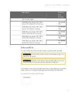
Spare parts and model numbers
For details on the spare parts and their part numbers, refer to the
section Hardware Components in this guide.
Chapter 5 - Maintenance
Содержание CN100
Страница 8: ...8 Chapter 2 Overview ...
Страница 13: ...13 Figure 3 3 Redundant Controller CCA Figure 3 4 Redundant Controller DINRAIL Chapter 3 Hardware Components ...
Страница 16: ...16 Chapter 3 Hardware Components ...
Страница 42: ...42 Chapter 5 Maintenance ...
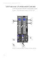
Страница 45: ...45 The various LED states are detailed in the following table Chapter 6 Diagnostics and Troubleshooting ...
Страница 50: ...50 Chapter 6 Diagnostics and Troubleshooting ...