


® U.S. Registered Trademark
Copyright © 2004 Honeywell International Inc. • All Rights Reserved
INSTALLATION INSTRUCTIONS
62-0216
C7046A,B,C,D
Air Temperature Sensors
APPLICATION
The C7046 series of Air Temperature Sensors function
as primary and/or secondary sensors in electronic control
systems.
INSTALLATION
When Installing this Product...
1.
Read these instructions carefully. Failure to follow
them could damage the product or cause a hazard-
ous condition.
2.
Check the ratings given in the instructions and on
the product to make sure the product is suitable for
your application.
3.
Installer must be a trained, experienced service
technician.
4.
After installation is complete, check out product
operation as provided in these instructions.
CAUTION
Electrical Shock or Equipment Damage
Hazard.
Can shock individuals or short equipment
circuitry.
Disconnect power supply before installation.
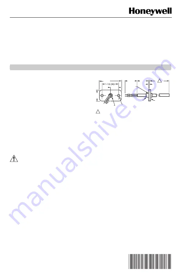
The sensor assembly (see Fig. 1) consists of an
aluminum sensor probe (element housed internally) with
attached flange that can be mounted on a flat duct or
plenum surface, or in a 2 in. by 4 in. (51 by 102 mm)
junction box using two No. 8 screws. Connections to the
sensor are made through two 6 in. (152 mm) leadwires.
Fig. 1. C7046A,B,C,D Air Temperature
Sensor dimensions in in. (mm).
NOTE: Sensor probe diameter is 1/4 in. (6 mm).
Location
The sensor should be located in the air duct or plenum
where it will sample an average air temperature. Avoid
locations where air stratification can cause sensing
errors.
Mounting
Mounting on Flat Duct or Plenum Surface (Fig. 2)
1.
Cut a 3/8 in. (9.5 mm) hole in the duct or plenum
surface at the desired location.
2.
Insert sensor probe into the duct or plenum until
the flange rests against the duct or plenum wall.
3.
If necessary, use the flange as a template to mark
and drill two holes for No. 8 mounting screws.
4.
Fasten the sensor to the duct or plenum surface
with two No. 8 sheet metal screws (not provided).
Mounting in a Junction Box (Fig. 3)
1.
Cut a 3/8 in. (9.5 mm) hole in the duct or plenum
surface at the desired location.
2.
Remove the center rear knockout from the junction
box and insert the sensing probe through the
knockout with the flange flat against the outlet box.
3.
Using the flange as a template, mark and drill two
holes in the junction box and the duct or plenum
surface for No. 8 mounting screws.
4.
Insert sensor probe through both the junction box
knockout and the 3/8 in. (9.5 mm) hole drilled in the
duct or plenum and fasten the junction box and
sensor to the duct or plenum surface.
1/4 (6)
DIAMETER (2 HOLES)
M22402A
1
(25)
3/4 (19)
2 (51)
1 (25)
1/16 (2)
8 (203)
NEOPRENE
GASKET
5/16 (9) DIAMETER
(BUSHING)
LOCKING PUSH
NUTS (2)
PLASTIC
BUSHING
1
INSERTION LENGTH DEPENDS UPON THE MODEL.
1