background image

Wireless Control And Submenus

When you step through the main menu there are sections for wireless communication, including
ISM, Wi-Fi, and Mesh radio.

It is also necessary to select a Primary Modem if theAreaRAE Plus/Pro is equipped with both
ISM and Wi-Fi modems.

ISM Settings

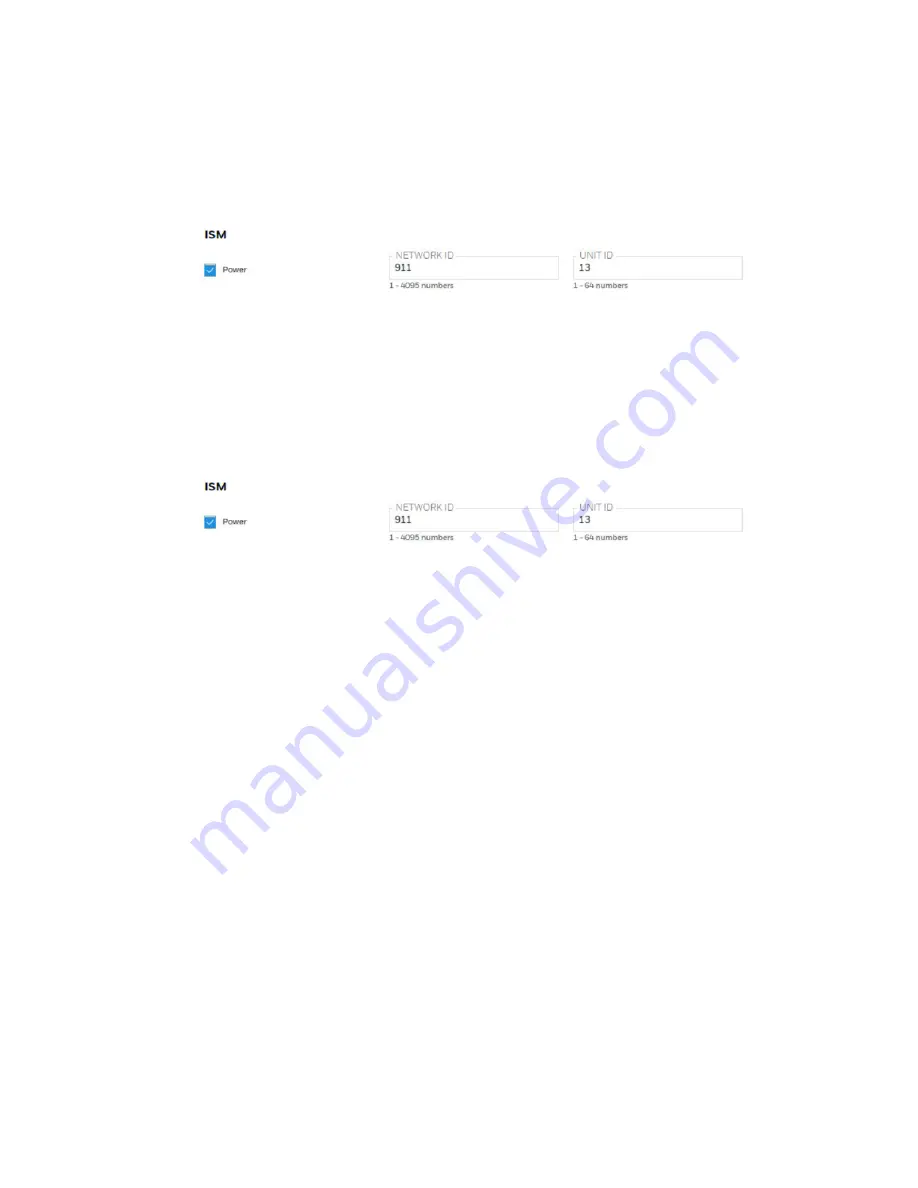
Every network using ISM radio must have a Network ID, which identifies that network and all
equipment operating in that network. All AreaRAE Plus/Pro and RAELink3 (or other RAELink
model) Host, Repeater, and Remote wireless modems in the same AreaRAE network need to be
configured with the same Network ID. Each device on the network must have a unique Unit ID.

Note: ISM Settings can be adjusted in the AreaRAE Plus/Pro’s Wireless menu under “ISM.”

AreaRAE

34

User Manual

Содержание AreaRAE Plus

Страница 1: ...AreaRAE WIRELESS MULTI GAS MULTI THREAT DETECTOR ...

Страница 2: ......

Страница 3: ... Of Active Sensors 25 Glance Mode 25 Menus 26 Wireless Operation 27 Broadcast On Alarm And Remote Unit Sleep Wakeup 28 Wireless Control And Submenus 34 ISM Settings 34 Wi Fi Settings 35 Secure Wireless Access Point Configuration 35 Setting Wi Fi Communication Parameters in Safety Suite Device Configurator 36 Relays for Controlling External Equipment 41 Battery 44 Charging 44 Battery States 45 Exte...

Страница 4: ...nced User Mode 83 Policy Enforcement 84 Setting Policy Enforcement 84 Deactivating Policy Enforcement 87 Calibration and Testing 88 Manual Alarms Test 88 Bump Testing and Calibration 88 Span Calibration 91 Three Point Calibration for Enhanced Linearity with Extended Range and ppb PID Sensors 91 Datalog Transfer Monitor Configuration and Firmware Upgrades Via Computer 97 Downloading Datalogs And Pe...

Страница 5: ...ollecting Gas Samples 119 Base Plate for Tripod Mounting Optional 120 Replacing the Pump 121 Alarms Overview 123 Alarm Signals 123 Changing the Alarm Mode 123 Diagnostic Mode 124 Enter Diagnostic Mode 124 Adjusting Alarm LEDs Buzzer 124 Adjusting LCD Contrast 124 Pump Stall Threshold Adjustment 125 Exit Diagnostic Mode 132 Alarm Signal Summary 133 Troubleshooting 135 Specifications 136 AreaRAE Plu...

Страница 6: ...he low alarm set point A bump test is also recommended if the monitor has been subjected to physical impact liquid immersion an Over Limit alarm event or custody changes or anytime the monitor s performance is in doubt To ensure greatest accuracy and safety only bump test and calibrate in a fresh air environment The monitor should be calibrated every time it does not pass a bump test but no less f...

Страница 7: ...MANCE UNIQUEMENT LA PORTION POUR DÉTECTER LES GAZ COMBUSTIBLES DE CET INSTRUMENT A ÉTÉ ÉVALUÉE CAUTION BEFORE EACH DAY S USAGE SENSITIVITY OF THE LEL SENSOR MUST BE TESTED ON A KNOWN CONCENTRATION OF METHANE GAS EQUIVALENT TO 20 TO 50 OF FULL SCALE CONCENTRATION ACCURACY MUST BE WITHIN 0 AND 20 OF ACTUAL ACCURACY MAY BE CORRECTED BY CALIBRATION PROCEDURE ATTENTION AVANT CHAQUE UTILISATION JOURNALI...

Страница 8: ...Code T4 C22 2 No 152 M1984 ANSI ISA 12 13 01 2013 20º C Tamb 50º C CAUTION READ AND UNDERSTAND INSTRUCTION MANUAL BEFORE OPERATING OR SERVICING ATTENTION LIRE ET COMPRENDRE MANUEL D INSTRUCTIONS AVANT D UTILISER OU SERVICE FCC Part 15 Statement This device complies with Part 15 of the FCC rules Operation is subject to the following two conditions 1 This device may not cause harmful interference an...

Страница 9: ...nt into an outlet on a circuit different from that to which the receiver is connected Consult the dealer or an experienced radio TV technician for help Under Industry Canada regulations this radio transmitter may only operate using an antenna of a type and maximum or lesser gain approved for the transmitter by Industry Canada To reduce potential radio interference to other users the antenna type a...

Страница 10: ...na 4 9dBi Gain of antenna 2 5dBi Max Type of antenna Omnidirectional Type of antenna Omnidirectional Type of antenna Omnidirectional Type of antenna Omnidirectional Impedance of antenna 50 ohms Impedance of antenna 50 ohms Impedance of antenna 50 ohms Impedance of antenna 50 ohms Le présent émetteur radio identifier le dispositif par son numéro de certification ou son numéro de modèle s il fait pa...

Страница 11: ...fied by Divisions PGM 65XXX is intended to be used in hazardous areas classified for Class I Div 2 within the temperature range of 20º C to 50º C where gases of explosion groups A B C or D and temperature code T4 may be present INSTRUCTIONS FOR SAFE USE WARNING Read and understand instruction manual before operation or servicing AVERTISSEMENT Lisez et comprenez le manual d instructions avant d uti...

Страница 12: ...the area is known to be non hazardous ii The battery pack shall only be charged or replaced in a non hazardous location iii The sensors shall only be replaced in a non hazardous location iv The external connection to the PGM 65xxx shall be in accordance to control drawing W01 0901 CTL The external alarms that are to be connected to PGM 65xxx must be suitable for the hazardous location where they a...

Страница 13: ...must undergo separate collection and recycling from general or household waste Please use the return and collection system available in your country for the disposal of this product Sensor Specifications Cross Sensitivities And Calibration Information For information on sensor specifications cross sensitivities and calibration information refer to RAE Systems Technical Note TN 114 Sensor Specifica...

Страница 14: ...amp PID 0 1 ppm 4R 9 8eV Lamp PID 1 ppm 7R 10 6eV Lamp PID 10 ppb 4R 10 6eV Lamp PID 10 ppb 4R 9 8eV Lamp PID 1 ppm Combustible LEL LEL NDIR CO2 Sensor CO2 CO2 Toxic EC Up to 6 Up to 6 Supported Sensors O2 CO CO ext CO H2 H2S H2S ext SO2 NO NO2 HCN NH3 PH3 HCl HF ETO A ETO B ETO C Cl2 ClO2 H2 O2 CO CO ext CO H2 H2S H2S ext SO2 NO NO2 HCN NH3 PH3 HCl HF ETO A ETO B ETO C Cl2 ClO2 H2 Other Sensors G...

Страница 15: ...opening tool if instrument is equipped with a PID sensor l 7R PID cover opening tool if instrument is equipped with a PID sensor l PID lamp removal tool if instrument is equipped with a PID sensor l Lamp cleaning kit isopropanol l T type calibration tube l QuickStart Guide l CD with documentation l CD with ProRAE Studio II instrument configuration and data management software l Calibration and tes...

Страница 16: ...nsor data and alarm status is achieved via ProRAE Guardian software Key Features l Up to seven gas sensors PID LEL CO2 Toxics l Dedicated radiation sensor slot Gamma sensor l RAEMet station for wind speed and direction ambient temperature and relative humidity l Multiple onboard wireless options Primary radio ISM 900 2400 MHz Wi Fi Secondary radio Mesh l CID2 certified for U S and Canada l Standar...

Страница 17: ...AreaRAE 16 User Manual ...

Страница 18: ...ht and top sides The rubber boot has integral caps for covering the ports when they are not in use IMPORTANT Keep all ports covered when they are not in use This keeps moisture and debris out of the ports and contributes to the instrument s intrinsic safety AreaRAE 17 User Manual ...

Страница 19: ...terface consists of the display alarm LEDs an alarm buzzer and three keys Display Overview The LCD display provides visual feedback that includes the sensor types readings alarm status battery condition and other information AreaRAE 18 User Manual ...

Страница 20: ...ss status the ISM or Wi Fi radio is off ISM or Wi Fi radio signal 0 to 19 ISM or Wi Fi radio signal 20 to 39 ISM or Wi Fi radio signal 40 to 79 ISM or Wi Fi radio signal 80 to 100 ISM or Wi Fi Long haul radio type ISM or Wi Fi RTR Number of Mesh Routers connected STD Number of standard mesh radio devices connected GPS enabled and power is off flashing Cannot find satellite 1 to 3 satellites 4 to 8...

Страница 21: ...0 Battery error Sensor due for calibration Sensor due for a bump test All electrochemical sensors tested and calibrated to policy tick mark all sensors have been bump tested and calibrated no sensor is overdue for a bump test or calibration according to the intervals configured on the instrument This icon is not shown if any sensor is due for bump testing or calibration or if policy enforcement is...

Страница 22: ...Temperature Relative humidity AreaRAE 21 User Manual ...

Страница 23: ...io or Wi Fi use specific icons to indicate functionality Icon Description ISM or Wi Fi power is off Cannot find network Received signal strength is 0 and 20 Received signal strength is 20 and 40 Received signal strength is 40 and 60 Received signal strength is 60 and 80 Received signal strength is 80 AreaRAE 22 User Manual ...

Страница 24: ...re mapped to the keys These change as menus change but at all times the left pane corresponds to the Y key the center pane corresponds to the MODE key and the right pane corresponds to the N key Here are examples that show the relationships of the keys and functions In addition to the functions described above any of the keys can be used to manually activate display backlighting Press any key when...

Страница 25: ... direction 1 Press and hold N for 3 seconds 2 When the arrow changes from pointing to the right to pointing to the left release your finger Now when you press N you step back through the screens To change direction again Press and hold N for 3 seconds and then release Note Changing direction does not work with all screens It works primarily in submenus AreaRAE 24 User Manual ...

Страница 26: ...r support personnel Glance Mode can be enabled disabled via Safety Suite Device Configurator SSDC Enter Glance Mode Note The instrument must be configured so that Glance Mode is turned on the default mode is Off This can be done in Safety Suite Device Configurator SSDC With the AreaRAE Plus Pro turned off press and hold Y to enter Glance Mode The feature is latched meaning that it runs even after ...

Страница 27: ...s Glance Mode Menus The reading menus are easy to step through by pressing the N key Notes l If the instrument is not equipped with a VOC sensor PID or is not equipped with an LEL sensor then screens for those sensors VOC Gas Status and LEL Gas Status respectively are not shown l If ISM or Wi Fi is not the primary modem its menu is not displayed Operation Mode Navigation AreaRAE 26 User Manual ...

Страница 28: ...the AreaRAE Plus Pro to a PC running Safety Suite Device Configurator SSDC to monitor them as well as the AreaRAE Plus Pro Note If the AreaRAE Pro or AreaRAE Plus is equipped with Wi Fi and Wi Fi is used as the primary radio instead of ISM then a Wi Fi access point substitutes for the RAELink3 Host Note The ISM radio acts as a repeater providing extended range for other instruments operating with ...

Страница 29: ... message to the entire system via ISM or Wi Fi when an instrument goes into alarm You can set the Alarm Interval to the time after each alert to be repeated this is set in seconds 2 seconds is the default value You can select specific units on the network to wake or put to sleep as well as send a message that you type in the Message field Send Message Broadcast message Type a message that you want...

Страница 30: ...elect sequential group Control Click to select individuals View Messages In AreaRAE Plus Pro The AreaRAE Plus Pro stores up to 10 received messages To view messages 1 Hold the MODE and N keys until you enter Programming Mode a password may be required see See Programming on page 50 for more information for details 2 Select Wireless 3 Scroll down to Message 4 Click Y to select A list of messages ac...

Страница 31: ...tor SSDC User s Guide for details Wake Unit Up Put Unit To Sleep There are two ways to wake the ProRAE Guardian On the instrument or from Safety Suite Device Configurator SSDC Put Unit To Sleep From Safety Suite Responder If the AreaRAE Plus Pro is on a network with Safety Suite Responder you can put it to sleep remotely from the same screen where you send messages 1 Select the instrument you want...

Страница 32: ... screen goes dark Wake Unit Up At Instrument When the AreaRAE Plus Pro is in Sleep mode the display is dark and no information is shown To wake it 1 Press any key on the instrument 2 The Password screen is shown Input the AreaRAE Plus Pro s password AreaRAE 31 User Manual ...

Страница 33: ... screen goes dark again This is an anti tampering feature Wake Unit Up From Safety Suite Responder If the AreaRAE Plus Pro is on a network with Safety Suite Responder you can wake it remotely from the same screen where you send messages 1 Select the instrument you want to wake up 2 Click the wake up sleep unit icon AreaRAE 32 User Manual ...

Страница 34: ...The instrument should wake up and begin monitoring immediately AreaRAE 33 User Manual ...

Страница 35: ...ttings Every network using ISM radio must have a Network ID which identifies that network and all equipment operating in that network All AreaRAE Plus Pro and RAELink3 or other RAELink model Host Repeater and Remote wireless modems in the same AreaRAE network need to be configured with the same Network ID Each device on the network must have a unique Unit ID Note ISM Settings can be adjusted in th...

Страница 36: ...ses a Wi Fi wireless network to transmit data related to its current and past activity To protect these data against unauthorized access Honeywell recommends the following when configuring your wireless network l Set a unique network name SSID Do not use the default name l Set unique administrative credentials username and password that control the configuration settings of your Access Point Route...

Страница 37: ...er Communications Mode 4 Press Y 5 Select PC The message on the display should say Ready To Communicate With Computer 1 Start Safety Suite Device Configurator SSDC 2 Log in using your Administrator s password 3 When your Wi Fi equipped instrument is detected click on its serial number 4 Click the Settings tab to view the current settings from the Wi Fi equipped instrument 5 Scroll down until you f...

Страница 38: ...you are using DHCP you do not have to provide these because they will be filled in automatically Channels and Security Check with your system administrator for the settings in this section Security Mode Different types of wireless security guard your network against possible instances of unauthorized access Using security you can l Ensure that no one can easily connect to your wireless network wit...

Страница 39: ...Then set your Security Key Warning Using a network with security disabled is not recommended AreaRAE 38 User Manual ...

Страница 40: ... reuse passwords used in other systems or for other purposes Avoid using examples found on the Internet in literature etc l Use a long sequence of random characters at least eight characters l Use a mix of different types of characters such as uppercase and lowercase letters numbers punctuation marks etc l To make the password easier to remember begin with a sentence verse book title line from a s...

Страница 41: ...D Server IP This is the destination IP address for the instrument to communicate with a computer running Safety Suite Device Configurator SSDC Server Port The port number is distinct from any physical port on a computer such as a COM port or an I O port address It is a 16 bit address that exists only for the purpose of passing certain types of information to the correct location above the transpor...

Страница 42: ... Normally Closed default can be changed to Normally Open by using Safety Suite Device Configurator SSDC software Type Dry Contact Maximum voltage 24VDC Maximum amperage 250mA Relay contact rating 24V 250mA Relays open to indicate High Low and Sensor or Pump Failure status When there is a pump failure Relay 3 s state changes to activate an alarm Note If an external device is not connected keep the ...

Страница 43: ...n2 Relay1 output Pin3 Relay2 output Pin4 Relay3 output A mating connector for wiring to external devices is available from electronics distributors Samtec part number ACP 16 03 G 00 30 S BC O 1 Test Setup For Relays AreaRAE 42 User Manual ...

Страница 44: ...sors 2 Low Instant reading reaches the low limitation of any sensor installed 3 Fail Pump Stall Any sensor in Fail alarm VOC sensor in Lamp alarm LEL sensor in Over alarm Pump Stall alarm IMPORTANT The external devices that are to be connected to the AreaRAE Plus Pro must be suitable for the hazardous location where they are mounted The wiring method shall be to local electrical code and installat...

Страница 45: ... recharge remove or replace the battery only in an area known to be non hazardous Do not mix old and new batteries or batteries from different manufacturers Charging Note Batteries should be charged in an environment where the temperature is in the range of 32 to 104 F 0 to 40 C Follow this procedure to charge the AreaRAE Plus Pro 1 Remove the cover over the AreaRAE Plus Pro s power port 2 Plug th...

Страница 46: ...he screen while auto cleaning is taking place IMPORTANT Always securely close the cover over the power port when not charging This keeps moisture and debris out of the port Battery States The battery icon on the display shows how much charge is in the battery and alerts you to any charging problems Full charge 2 3 charge 1 3 charge Low charge Battery alert When the battery s charge falls below a p...

Страница 47: ...rea known to be non hazardous Do not mix old and new batteries or batteries from different manufacturers External Battery Charger LED Indicators LEDs on the External Battery Charger indicate the following LED Indication Solid red NTC fault bad battery battery standby Blinking red Charging but the capacity is too low to power the instrument less than 10 Blinking green Charging The capacity is suffi...

Страница 48: ...ation for as long as you like To resume the progression press MODE again Even if you pause the progression of screens the startup process is not interrupted Note To speed up the startup time the number of screens shown on startup can be reduced by enabling the Fast Startup option under Programming Monitor Then the AreaRAE Plus Pro s main reading screen appears It displays instantaneous readings si...

Страница 49: ...ely shows inflow and outflow as shown here If there is a pump failure or obstruction that disrupts the pump the alarm sounds and you see this icon blinking on and off Once the obstruction is removed you can try to restart the pump by pressing the Y If the pump does not restart and the pump stall alarm continues consult the Troubleshooting section of this guide or contact Honeywell Technical Suppor...

Страница 50: ...ose calibration is overdue l The defined period of time between calibrations has been exceeded l If you have changed the calibration gas type without recalibrating the instrument l The sensor has failed a previous calibration Bump Status The instrument displays this icon next to the sensor that requires bump test A bump test is required and indicated by this icon if l The defined period of time be...

Страница 51: ...ramming in Basic Mode Programming in Basic Mode is limited to calibration only A password is required to access other programming menus 1 To enter Programming Mode press and hold MODE and N until you see the Password screen 2 Input the 4 digit password l Increase the number from 0 through 9 by pressing Y l Step from digit to digit using N l Press MODE when you are done AreaRAE 50 User Manual ...

Страница 52: ...ter Programming Mode the Calibration menu is highlighted You cannot access other menu items and you can only perform the following types of calibration l Fresh Air l Multi Sensor Span l Single Sensor Zero l Single Sensor Span The following require password access in Basic Mode or can be directly accessed in Advanced Mode l Multi Sensor Bump l Single Sensor Bump l Cal Reference l Change Cal Gas l M...

Страница 53: ...word is necessary in Advanced Mode 2 Press N to step through the programming screens Note Holding down N advances quickly through the menu options When a menu item is selected its name is shown at the top of the screen and its icon is enlarged To enter a menu and view or edit parameters in its submenus press Y AreaRAE 52 User Manual ...

Страница 54: ...lue Change Span 2 Value Message menu item appears only when messages have been received by the AreaRAE Plus Pro 7R sensors and 4R ppb sensors Editing and Selecting Parameters and Sensors There are a few basic ways to edit parameters select sensors and perform other activities in the AreaRAE Plus Pro The actions performed by pressing keys always match 1 to 1 with the boxes along the bottom of the d...

Страница 55: ...dry zero air if used 4 Press Y to start fresh air calibration 5 A countdown screen appears You can abort the calibration at any time during the countdown by pressing N Note Dotted line indicates automatic progression 6 If the calibration is not aborted the display shows the sensor names and tells you whether the fresh air Multi Sensor Span Depending on the configuration of your AreaRAE Plus Pro an...

Страница 56: ...bration 6 A countdown screen appears You can abort the calibration at any time during the countdown by pressing N Note Dotted line indicates automatic progression 7 If the calibration is not aborted the display shows the sensor names and tells you whether the zero calibration passed or failed followed by the sensors zero calibration readings Single Sensor Span Calibration Instead of performing a s...

Страница 57: ...y of the sensors it means that the sensor is due for a full calibration To perform span calibration of an individual sensor follow these steps 1 At the Calibration Menu select Single Sensor Span 2 Select a sensor to calibrate from the list 3 Install the T tube and connect it to a source of calibration gas 4 Verify that the displayed calibration value meets the concentration specified on the gas cy...

Страница 58: ...e AreaRAE Plus Pro equipped with a gamma sensor to check the readings Place the check source near the upper middle of the rear of the instrument and hold it until you see the Gamma reading change in the display Single Sensor Span 2 Calibration If the sensor is configured to allow a second calibration after the first span calibration the display provides a prompt With a label of Span 2 Calibration ...

Страница 59: ...instrument and pressing Y If you do not want to perform a multiple bump test press MODE Note You can abort a multiple bump test by pressing N once testing has started When the Multi Bump test is done a screen is shown with the sensor names and either Pass or Fail shown next to them Single Sensor Bump This menu allows a bump test to be performed on an individual sensor of your choice Note If a bump...

Страница 60: ... value meets the concentration specified on the gas cylinder 5 Start the flow of calibration gas Note Dotted line indicates automatic progression 6 Press Y to start calibrating or wait for the bump test to start automatically 7 A countdown screen appears You can abort the bump test at any time during the countdown by pressing N 8 If the bump test is not aborted the display shows the sensor names a...

Страница 61: ...eight M W and correction factor CF Multi Cal Select This menu allows you to define a group of sensors to be bump tested and span calibrated together Simultaneous testing and calibration of multiple sensors shortens the bump test and calibration processes and reduces the number of individual gas cylinders you need For example it may be more efficient to use a single cylinder with a four gas mix inc...

Страница 62: ...of measure ppm LEL etc are shown on the display 1 Scroll down the list of sensors using the N key 2 Press Y to select it 3 Press N to step through the digits 4 Press Y to increase the number from 0 through 9 Once the number 9 is reached pressing Y causes the numbers to wrap around to 0 and count up again 5 Once you have set the desired value press MODE for Done This registers the new span value Ar...

Страница 63: ...the new second span value 5 Press Y for Save and N for Undo LEL Calibration Procedure You must perform a separate zero calibration for the LEL sensor and then perform a span calibration Important Before calibrating make sure pump is on its high setting This is in the Pump Speed submenu under the Monitor menu item To calibrate the LEL sensor follow these two procedures Zero Sensor Calibration For T...

Страница 64: ...alibration gas 7 Press Y to start calibration 8 When calibration is complete shut off the calibration gas flow and disconnect the calibration tubing 9 Press MODE to exit to the menu You may perform other calibrations Otherwise exit Measurement The submenus for Measurement include Sensor On Off Change Measurement Gas and VOC and Gamma if equipped Measurement Units AreaRAE 63 User Manual ...

Страница 65: ...ensor s name indicates it is turned on 1 Scroll down the list of sensors using the N key 2 Add or remove that gas from the list by pressing Y An X in a box to the left of a sensor s name indicates it is selected 3 Once you have made all your selections press MODE for Done AreaRAE 64 User Manual ...

Страница 66: ...the instrument Note The first gas in the list is always isobutylene it cannot be removed from the list l Last Ten is a list of the last ten gases used by your instrument The list is built automatically and is only updated if the gas selected from Custom Gases or Library is not already in the Last Ten This ensures that there is no repetition l Gas Library is a library that consists of more than 200...

Страница 67: ...ubic meter micrograms per cubic meter PID for VOC ppm parts per million EC mg m3 milligrams per cubic meter EC µrem h mrem h microrems and millirems per hour Gamma µSv h mSv h microSieverts and milliSieverts per hour Gamma µR h mR h microRoentgens and milliRoentgens per hour Gamma µGy h mGy h microGrays and milliGrays per hour Gamma ppm parts per million CO2 VOL Volume CO2 ºF Fahrenheit degrees Te...

Страница 68: ...erage Alarm Note Some alarm settings are not applicable to all sensors If a setting is irrelevant to a sensor for example STEL for a gamma radiation sensor then that sensor does not appear in the list Alarm Mode You can program the AreaRAE Plus Pro so that there are two ways to shut off an alarm Auto Reset When the alarm condition is no longer present the alarm stops automatically Latch You must m...

Страница 69: ... User ID and other parameters The AreaRAE Plus Pro memory is sufficient to record six months worth of data for 12 sensors and GPS at one minute intervals 24 7 All data are retained even after the unit is turned off in non volatile memory so that they can be downloaded at a later time to a PC Clear Datalog This operation erases all data stored in the datalog Select Clear Datalog and then Yes Note O...

Страница 70: ... a sensor off in the list does not change or erase its settings Data Selection Data Selection allows you to select which types of data are stored and made available when you download your datalog to a computer via Safety Suite Device Configurator SSDC software You can choose any or all of four types of data you must choose at least one l Minimum l Average l Maximum l Real Time AreaRAE 69 User Manu...

Страница 71: ...Manual Datalogging occurs only when you manually initiate it see below for details Note You can only choose one datalog type to be active at a time About Manual Datalogging When the instrument is set to Manual Datalog you can turn datalogging on and off by repeatedly pressing N and stepping through the screens from the main display until you reach the screen that says Start Datalog AreaRAE 70 User...

Страница 72: ...rough the screens until you reach the screen that says Stop Datalog Press Y to stop datalogging The screen displays Datalog Stopped for a few seconds before displaying Start Datalog and the datalog interval You can restart it anytime by pressing Y from that screen Memory Full Action When the internal datalog memory is full the AreaRAE Plus Pro can either stop collecting data Stop When Full or go b...

Страница 73: ... GPS GPS receivers operate by line of sight with global positioning satellites A receiver must be able to get signals from at least four satellites in order to calculate longitude and latitude there are currently 30 GPS satellites orbiting the earth The more satellites a GPS receiver can see the more accurate and reliable the positioning For a GPS equipped AreaRAE Plus Pro to work properly it must...

Страница 74: ...int to point and point to multi point networking with Safety Suite Device Configurator SSDC software Options include l Power On Off l PAN ID l Channel l Factory Reset On Off 1 Press Y to see on or off state and which is selected 2 Press N to scroll to On or Off 3 Press Y to select 4 Press Y to Save You can also press N to undo PAN ID The AreaRAE Plus Pro and any other devices that you want to inte...

Страница 75: ...hoice or press N to undo your changes Note You cannot change the channel setting on an instrument equipped with a radio modem that operates at a frequency of 868 MHz Factory Reset Restore all the wireless settings to their original factory defaults Caution Once you reset the wireless settings you cannot retrieve any of the settings deleted by performing this reset l Press Y to reset the wireless s...

Страница 76: ...e change Power On Off You can turn the ISM radio s power on or off 1 Press Y to see on or off state and which is selected 2 Press N to scroll to On or Off 3 Press Y to select 4 Press Y to Save You can also press N to undo Network ID Every ISM network must have a Network ID which identifies that network and all equipment operating in that network All instruments including the host repeaters etc in ...

Страница 77: ...ease the number and N to advance to the next digit 2 After moving to the last digit and making changes press MODE l Press Y to save the change l Press N to undo the change Wi Fi You can turn the Wi Fi radio s power on or off 1 Press Y to see on and off states and which is selected 2 Press N to scroll to On or Off 3 Press Y to select 4 Press Y to Save You can also press N to undo AreaRAE 76 User Ma...

Страница 78: ... s setup 8 Scroll down to Wi Fi This is where you see the current Wi Fi parameters and can set new ones 9 It is recommended that you select Use DHCP to dynamically set up the correct settings If you must use a Static IP Address many corporate enterprises require it check with your I T administrator 10 Settings for Security Mode Security Key and SSID must match the settings on the router associated...

Страница 79: ...art l Fast Startup l Language l Site ID l User ID l Secure In Place Press N to advance through the submenus and when you reach the last one it returns to the first selection LCD Contrast The display s contrast can be increased or decreased from its default setting You may not need to ever change the default setting but sometimes you can optimize the display to suit extreme temperature and ambient ...

Страница 80: ...on and is ready for use It skips showing you many settings and is best suited to environments where the AreaRAE Plus Pro is turned on and off very often during a given day If Fast Startup is not selected then when the instrument starts it shows you details of each sensor including calibration information high and low alarm settings etc 1 Press Y to see on or off state and which is selected 2 Press...

Страница 81: ...ock Requires that you enter the system password to power down the AreaRAE Plus Pro When Power Down Lock is selected every time you want to shut down the AreaRAE Plus Pro you must hold the MODE button for five seconds and then at the prompt input the password Note This feature is disabled by default and is configurable via Safety Suite Device Configurator SSDC and via the AreaRAE Plus Pro s menu Sc...

Страница 82: ...ress Y to Save You can also press N to undo Your options are l Power Down Lock l Screen Lock l Remote Monitoring Mode l All Disabled Accessing AreaRAE Set To Secure In Place When The Password Is Lost If the instrument is locked via Secure In Place and you lose the password it is possible to recover access to the AreaRAE This requires that the Firmware version in the AreaRAE is v1 06 or higher Also...

Страница 83: ...ick on the device s serial number to view the settings 6 Scroll down to Instrument User Preferences View and or change the password in the Passcode window Note The password screen only remains viewable for one minute After that minute AreaRAE 2 returns to the locked main reading page Therefore make changes quickly If the screen returns to the locked page repeat the process beginning with step 2 7 ...

Страница 84: ...Basic User Mode some restrictions are applied including password protection that guards against entering Programming Mode by unauthorized personnel Advanced User Mode In Advanced User Mode there are no access restrictions you do not need a password and the AreaRAE Plus Pro provides the indications and data you need most for typical monitoring applications AreaRAE 83 User Manual ...

Страница 85: ...us Pro displays a screen that informs the user that the instrument requires either a bump test or a calibration If both are required then they are shown in sequence Note Policy enforcement features are disabled by default Setting Policy Enforcement You must use Safety Suite Device Configurator SSDC to make changes to Policy Enforcement settings The procedure requires connecting the AreaRAE Plus Pr...

Страница 86: ... calibration requirement in a Policy Violation report Bump The user is prompted to bump test the instrument when a bump test is due as set by the bump test interval There are two programmable options l Can t Bypass Unless a bump test is performed the instrument cannot be used and the only option is to turn off the instrument l Can Bypass If a bump test is due but the user does not want to perform ...

Страница 87: ...tions inSafety Suite Device Configurator SSDC you must upload the changes to the instrument Click Save 9 Exit Safety Suite Device Configurator SSDC 10 Press Y on the AreaRAE Plus Pro to exit Communication Mode AreaRAE 86 User Manual ...

Страница 88: ...Y and MODE until it starts up 3 After startup enter the password when prompted default is 0000 and press MODE 4 Press N repeatedly until you see the Enter Communications Mode screen 5 Press Y to enter Communications Mode 6 Safety Suite Device Configurator SSDC 7 Input the username and password the default username is administrator and the default password is Default123 8 Click LOG IN 9 Click on th...

Страница 89: ...ance but the user still has the responsibility to make sure all the alarms are enabled and functional Bump Functional Testing A bump test can be performed on an individual sensor Single Sensor Bump or a group of sensors Multi Sensor Bump combined into Multi Cal Select The same gas is used for a bump test as for calibration Typically two cylinders of calibration gas are needed to perform a bump tes...

Страница 90: ...gs shown are in the equivalent units of the calibration gas and not the measurement gas if different Bias Equilibration for Liquid O2 and other Biased Sensors Some electrochemical sensors NO NH3 Liquid O2 require a bias voltage to detect the gas while most do not Unbiased sensors may be shipped with a shorting pin across the electrodes to avoid an accidental bias The pin should be removed before i...

Страница 91: ...llion PID sensor should be zeroed with ambient air using a charcoal filter or a VOC zeroing tube Refer to the procedure on See VOC Zero Calibration Procedure for Enhanced Linearity with Extended Range and ppb PID Sensors on page 92 for more information Fresh Air Calibration This procedure determines zero points of most sensors The AreaRAE Plus Pro should be zero calibrated in clean air with 20 9 o...

Страница 92: ...PID sensors including high range ppm and ppb PID sensors Default calibration gas settings for AreaRAE Plus Pro PID sensors are as follows Sensor Specifications Zero Span Span 2 Third calibration point if enabled AreaRAE Plus Pro parts per billion ppb PID 0 to 2 000 ppm range 10 ppb resolution With a charcoal filter or VOC zeroing tube 10 ppm Isobutylene 100 ppm Isobutylene AreaRAE Plus Pro extende...

Страница 93: ... Tube by putting the ends into the small hole near the bottom of the tube box and snapping them off 3 Connect the VOC Zero Tube Adapter to the external filter on AreaRAE Plus Pro and then insert one end of the VOC Zeroing Tube into the adapter The arrow on the tube indicates the correct direction 4 Run the zeroing calibration procedure for the instrument 5 After zero calibration properly dispose o...

Страница 94: ... in the Safety Suite Device Configurator SSDC User s Manual 2 Click on the device s serial number to view the AreaRAE Plus Pro s current configuration information 3 Click on the Sensors tab 4 Scroll down until VOC sensor is visible 5 Click on the edit icon 6 Click on the checkbox to activate 3 Point Calibration 7 Click the Save button 8 When you are done quit Safety Suite Device Configurator SSDC ...

Страница 95: ...ch one end of a T to the external filter on the AreaRAE Plus Pro inlet You can use RAE Systems by Honeywell P N W01 3003 000 Calibrating Without a T Tube Use Teflon tubing to connect the calibration gas cylinder s regulator to the external filter on the AreaRAE Plus Pro inlet Multi Sensor Span Calibration This lets you perform a span calibration on multiple sensors simultaneously It requires using...

Страница 96: ...ibration reaches its conclusion it shows the sensor names and tells you whether the calibration passed or failed followed by the sensor readings Note If there are other sensors to be calibrated at this stage the screens will guide you through the process Single Sensor Span Calibration To perform span calibration of an individual sensor follow these steps 1 At the Calibration Menu select Single Sen...

Страница 97: ...e span calibration is done The LCD will display whether the calibration was successful and the reading for that calibration gas Note If the sensor calibration fails try again If calibration fails repeatedly turn off the instrument and then replace the sensor WARNING Do not replace sensors in hazardous locations AreaRAE 96 User Manual ...

Страница 98: ...n be downloaded from the AreaRAE Plus Pro to a computer and firmware updates can be uploaded to the AreaRAE Plus Pro via the USB port on the side Use the included USB cable to connect the AreaRAE Plus Pro to a computer running Safety Suite Device Configurator SSDC AreaRAE 97 User Manual ...

Страница 99: ...y pressing N repeatedly starting from the main measurement screen until you reach the Enter Communication Mode screen 4 Press Y Measurement and datalogging stop and the instrument is now ready to communicate with the PC The display now says Ready To Communicate With Computer 5 Start up the Safety Suite Device Configurator SSDC software login and detect the instrument following the directions provi...

Страница 100: ...the Rubber Boot In order to open the AreaRAE Plus Pro it is necessary to remove the belt clip and the rubber boot Note that there are two hex screws on the bottom rear side that secure the boot 1 Turn off the instrument 2 Remove the external filter 3 Remove the wind sensor if one is attached 4 Unscrew the two the two screws on each side 5 Slide the top part of the boot upward until it clears the t...

Страница 101: ...iscard it and replace it with a new filter P N 008 3022 000 Perform a pump stall test to make sure the inlet and the external filter are installed properly so that there are no leaks in the system IMPORTANT An AreaRAE Plus Pro must not be calibrated or operated without a filter Operation without a filter may damage the instrument AreaRAE 100 User Manual ...

Страница 102: ...t 3 Remove the cover The sensors are plugged into the slots 4 Gently lift out the desired sensor module with your fingers 5 Install the replacement sensor It can only go into its slot one way The connector inside the AreaRAE Plus Pro and the indexing guides are good visual indicators of how to set the sensor into position Make sure the indexing keys are aligned and press the sensor into place to e...

Страница 103: ... gas inlet side membrane filter side pointing downwards 3 Avoid storing the instrument for more than 12 hours in a way that sensors will be have their gas inlet side pointing upwards equivalent to the instrument s screen pointing downwards HF HCL Sensor Calibration It is important to understand and acknowledge that HF and HCl sensors are not as easy to use and calibrate as any other EC electrochem...

Страница 104: ...s two or more of the same kind including for example a 4R PID and a 7R PID to operate simultaneously Therefore if duplicate sensors are inserted in the slots when the instrument is turned on it automatically senses the redundancy and only allows operation of one of the sensors selecting the sensor in the location with the lowest number The exception is the PID sensor If both a 7R PID sensor and a ...

Страница 105: ...the PID module with your fingers 2 If the module requires replacement because the lamp does not illuminate or the module has been used past its expiration date place a new module into the slot being careful to match the indexing keys The sensor can only go into its slot one way Refer to step 11 for alignment information 3 If you want to open the sensor module to inspect and clean the lamp and sens...

Страница 106: ...5 Once the cap is removed set it aside 6 Now lift the sensor electrode panel from the module AreaRAE 105 User Manual ...

Страница 107: ... dry 8 Clean the lamp s window with a cleaning swab dipped in isopropanol lamp cleaner and allow it to dry Do not touch the lamp window with your fingers as the residual oils will shorten its life 9 Inspect the electrical contacts Clean them with a swab dipped in lamp cleaner if they appear to need cleaning make sure the contacts are not pressed down when you are done AreaRAE 106 User Manual ...

Страница 108: ... place and firmly pressing the cap back onto the top 11 Place the sensor module back into the AreaRAE Plus Pro Make sure the index points are aligned it can only go in one way 12 Carefully place the cap back onto the AreaRAE Plus Pro and tighten the screw AreaRAE 107 User Manual ...

Страница 109: ...new module into the slot being careful to match the indexing keys The sensor can only go into its slot one way If you want to open the sensor module to inspect and clean the lamp and sensor electrode panel you must use the special 7R PID Sensor Cover Opening Tool P N C04 2025 000 1 Press the tool down around the sensor module making sure to align the arrow on the module and the tool 2 Check that t...

Страница 110: ... flat blade screwdriver in the slot and gently pry up on the cover using the tool for leverage 5 Once the cover is loose remove the screwdriver 6 Lift the lid off exposing the sensor electrode panel AreaRAE 109 User Manual ...

Страница 111: ...7R PID Lamp Removal Tool P N C04 2026 000 to remove the lamp With the tool s collar retracted a press down around the top of the lamp b Then press down the collar so that the tool grips the lamp c 9 Gently lift the PID lamp out of the sensor module by pulling up AreaRAE 110 User Manual ...

Страница 112: ...g by wiping it with isopropanol using a cotton swab using moderate pressure After cleaning hold the lamp up to the light at an angle to detect any remaining film Repeat the process until the lamp window is clean Never use water solutions to clean the lamp Dry the lamp and the lamp housing thoroughly after cleaning CAUTION Never touch the window surface with the fingers or anything else that may le...

Страница 113: ...pect the large O ring gasket for damage If it is damaged discard it and use a new one 1 Place the O ring gasket in the compartment Inspect the O ring gasket for wear or damage first If necessary replace it 2 Press all the sensors firmly in place to ensure they are seated correctly 3 Set the sensor compartment cover on top of the compartment 4 Tighten the four screws Note Do not overtighten AreaRAE...

Страница 114: ...pack requires a Philips screwdriver To replace the AreaRAE Plus Pro battery 1 Turn the instrument off 2 Remove the filter from the front of the instrument 3 Place the instrument face down on a soft surface 4 Remove the four screws that hold the battery 5 Use your fingers to lift the battery out there are indents at each end AreaRAE 113 User Manual ...

Страница 115: ... battery into place 7 Tighten the four screws WARNING To reduce the risk of ignition of hazardous atmospheres recharge remove or replace the battery only in an area known to be non hazardous AreaRAE 114 User Manual ...

Страница 116: ...tor plug with the AreaRAE Plus Pro s receptacle using the indexing key and slot as a guide 4 Press the RAEMet s base into place and then turn the locking ring to tighten the connection Never force the connector in or out of the receptacle 5 Tighten the locking ring until the RAEMet sensor is firmly seated Do not turn the entire RAEMet sensor IMPORTANT If the RAEMet and AreaRAE receptacle are not a...

Страница 117: ... is in operation If it is removed from the AreaRAE Plus Pro during operation the display shows a Fail message to alert you Note Keep strong magnets away from the RAEMet sensor It contains a compass and strong magnetism can affect its accuracy AreaRAE 116 User Manual ...

Страница 118: ...mpartment aligning the antenna and turning the base of the antenna until it is snug IMPORTANT When the antenna is not attached to the instrument make sure the cover is securely closed to keep moisture and debris from entering the base AreaRAE 117 User Manual ...

Страница 119: ...es on page 101 for more information for details 2 Remove the gas plate 3 Place the filter over the CO sensor with the filter s fabric side facing up 4 Replace the gas plate Refer to See Battery Removal Replacement on page 113 for more information for details 5 Tighten the four screws 6 Start the AreaRAE Plus Pro 7 Recalibrate the CO sensor For further information on using a carbon filter to reduce...

Страница 120: ...a male luer connector P N 400 0073 000 and Tygon tubing P N 411 0018 037 Capturing samples requires a Tedlar sample collection bag 3 liters P N 500 0003 000 Note When collecting samples for evidence or later analysis it is recommended to use only the PID sensor Important Remove the Exhaust Gas Collector after capturing samples Do not leave the Exhaust Gas Collector attached during continuous monit...

Страница 121: ...removal of the instrument s rubber boot 1 Lay the AreaRAE Plus Pro on its back to provide access to the two threaded inserts 2 Match the plate to the instrument with its rib against the instrument s bottom 3 Align the hex head screws with the holes and press them into place 4 Use a hex wrench to tighten the screws Once the base plate is firmly attached to the AreaRAE Plus Pro stand the instrument ...

Страница 122: ...sor compartment cover 2 Turn it upside down and set it on a soft flat surface 3 The pump assembly is attached to the sensor compartment cover with two Philips screws Remove the two screws 4 Lift off the pump assembly 5 Pressing down on the gas plate with one hand disconnect the pump from internal tubing by gently pulling it out It has an inlet and outlet that are held in the two holes with rubber ...

Страница 123: ...mbly P N W01 3002 000 into place making sure that both the inlet and outlet from the pump go through the O rings into the two holes 8 Insert and tighten the two screws that attach the bracket to the housing 9 Replace the cover 10 Turn on the instrument and check for proper pump operation AreaRAE 122 User Manual ...

Страница 124: ...dition to gas and radiation alarms other alarms are available Furthermore the AreaRAE Plus Pro alarms if one or more of the following conditions occurs battery voltage low pump blocked PID lamp failed etc When the low battery alarm occurs there may be approximately 15 minutes of operating time remaining In this case it is recommended that you promptly change or charge the battery in a non hazardou...

Страница 125: ...dition you can adjust the repetition rate and loudness of the buzzer and the repetition rate and brightness of the LEDs 1 Start with the instrument turned off Hold down the Y and MODE keys until the AreaRAE Plus Pro starts 2 When you see the password screen input your 4 digit password and then press MODE 3 Once you have entered Diagnostic Mode press N until the Alarm screen is displayed 4 Press MO...

Страница 126: ...c Mode Also regardless of which method is used when you are done setting thresholds exit Diagnostic Mode and test the instrument before actual use Entering Diagnostic Mode to Set the Pump Stall Threshold 1 Start with the instrument turned off Hold down the Y and MODE keys until the AreaRAE Plus Pro starts 2 When you see the password screen input your 4 digit password and then press MODE 3 Once you...

Страница 127: ...ess Dynamic pump stall settings Now follow directions to change the pump stall threshold values using the method that matches your choice of either Dynamic or Static Setting Pump Stall Threshold Values Dynamic Method When the Dynamic pump stall threshold values are shown you can perform calibration to set the pump stall values dynamically Press MODE to begin calibration This screen is shown indica...

Страница 128: ...ress MODE to begin calibration There is a countdown shown in the box Press N anytime to abort the calibration and go back Once the countdown is finished this message is displayed AreaRAE 127 User Manual ...

Страница 129: ...inger over the inlet and allow the countdown to proceed Press Y anytime to abort and return to the previous screen When the countdown is finished the main Dynamic pump stall screen is shown AreaRAE 128 User Manual ...

Страница 130: ...mic pump stall calibration is complete You can now exit Diagnostic Mode Important When you are done setting thresholds exit Diagnostic Mode and test the instrument before actual use AreaRAE 129 User Manual ...

Страница 131: ...High Threshold Setting Static Method In Diagnostic Mode press the MODE key repeatedly until the Pump screen is displayed High should be highlighted Otherwise press Y to select the High value l The Idle value shown as a value for I should be 150 to 250 Record the value l Block the inlet and record the value after it goes up l The blocked value minus the Idle Unblocked value should be greater than 1...

Страница 132: ... and divide by 2 Blocked value Unblocked value 2 correct Stall High value l Press N to advance to the next Pump screen l Use the Y and N keys to increase or decrease the high value input the results of your calculation l Press MODE to register that value AreaRAE 131 User Manual ...

Страница 133: ... 100 counts Blocked value Unblocked value 100 l If it is greater than 100 then the pump is working correctly and tubing leading from the inlet is not leaking l To set the Low value first add the blocked and unblocked values and divide by 2 Blocked value Unblocked value 2 correct Stall Low value l Then using the Y and N keys set the Stall Low value to this number Verifying the Stall Low Setting Sta...

Страница 134: ...Low 2 beeps sec Low at sensor location Reading On Negative 1 beep sec Neg at sensor location 0 On STEL 1 beep sec STEL at sensor location Reading On TWA 1 beep sec TWA at sensor location Reading On Calibration Fail 1 beep sec Cal at sensor location Reading On Bump Fail 1 beep sec Bump at sensor location Reading On Datalog Full 1 beep sec Blinking datalog symbol Reading On Calibration Required Full...

Страница 135: ...h per second STEL Gas exceeds STEL limit 1 Beep flash per second Crossed pump icon flashes Inlet blocked or pump failure 3 beeps flashes per second Lamp flashes PID lamp failure 3 beeps flashes per second Empty battery icon flashes Low battery 1 flash 1 beep per minute CAL Calibration failed or needs calibration 1 beep flash per second NEG True sensor reading is below zero even though a zero readi...

Страница 136: ...Reasons Low ion concentration inside PID lamp especially in cold environment when first powered on Defective PID lamp or defective circuit Solutions Turn the unit off and back on Replace UV lamp Pump failed message Pump alarm Reasons Inlet probe blocked Direct connection to a gas outlet while the gas value is turned off Water trap filter sucks in water Water trap filter too dirty Water condensed a...

Страница 137: ...or pump failure Visible Alarm Bright LED 360 degree view Audible Alarm Dual buzzers 108 dB 1 m Data logging Continuous datalogging 90 days for 12 gas sensors and GPS at 1 minute intervals continuously Data Storage 24M bytes memory full action stop when full or wrap around Data Interval User configurable from 1 to 3 600 sec Wireless l Long Range ISM License free 900 to 928 MHz or 2 4GHz l Optional ...

Страница 138: ...ygen sensors l Three years for CO and H2S sensors l Two years for non consumable components and catalytic LEL sensor l Two years for 10 6eV 7R PID lamp l One year on all other sensors battery and other consumable parts l Six months for 9 8eV lamp PID sensor Optional sensors Specifications are subject to change AreaRAE 137 User Manual ...

Страница 139: ...60A PGM 6520A 2 N A Y 900MHz Y Y PGM 6560E PGM 6520E 3 900MHz Y 900MHz Y Y PGM 6560D PGM 6520D 4 2 4GHz N A 900MHz Y Y PGM 6560B PGM 6520B EMEA 1 2 4GHz N A 869MHz Y Y PGM 6560B PGM 6520B Asia Pacific 1 900MHz N A 900MHz Y Y PGM 6560A PGM 6520A 2 2 4GHz N A 900MHz Y Y PGM 6560B PGM 6520B China 1 2 4GHz N A 869MHz Y Y PGM 6560B PGM 6520B 2 N A Y 869MHz Y Y PGM 6560E PGM 6520E AreaRAE 138 User Manua...

Страница 140: ...rbon Monoxide 0 to 2 000 ppm 10 ppm Carbon Monoxide H2 comp 0 to 2 000 ppm 10 ppm Chlorine 0 to 50 ppm 0 1 ppm Chlorine dioxide 0 to 1 ppm 0 03 ppm Ethylene Oxide ETO A 0 to 100 ppm 0 5 ppm Ethylene Oxide ETO B 0 to 10 ppm 0 1 ppm Ethylene Oxide ETO C 0 to 500 ppm 10 ppm Hydrogen 0 to 2 000 ppm 2 ppm Hydrogen Chloride 0 to 15 ppm 1 ppm Hydrogen Cyanide 0 to 50 ppm 0 5 ppm Hydrogen Fluoride 0 5 to ...

Страница 141: ...ol 3 3 1 8 Ethyl acetate 2 2 4 Gasoline 1 3 2 6 Heptane n 1 1 2 5 Hexane n 1 1 2 1 Hydrogen 4 1 0 Isobutene Isobutylene 1 8 1 6 Isopropanol 2 2 2 Methane 5 1 0 Methanol 6 1 6 Methyl ethyl ketone 4 5 2 2 Octane n 1 2 7 Propane 2 1 1 4 Propene 2 1 6 Toluene 1 1 2 4 Turpentine 0 8 3 0 Note Values in bold type are confirmed with RAE Systems by Honeywell instruments Others shown in italic are calculate...

Страница 142: ...Manufacture To identify the year and month of manufacture refer to the two digit marking placed adjacent to the serial number on the instrument label according to the following table Year First digit Year code Month Second digit Month code 2014 R January 1 2015 S February 2 2016 T March 3 2017 U April 4 2018 V May 5 2019 W June 6 2020 A July 7 2021 B August 8 2022 C September 9 2023 D October A 20...

Страница 143: ...tinsford Road Nuffield Industrial Estate Poole Dorset BH17 0RZ United Kingdom Tel 44 0 1202 645 544 Fax 44 0 1202 645 555 Honeywell Analytics ZAC Athélia 4 375 avenue du Mistral Bât B Expace Mistral 13600 La Ciotat France Tel 33 0 4 42 98 17 75 Fax 33 0 4 42 71 97 05 Honeywell Analytics Elsenheimerstrasse 43 80687 München Germany Tel 49 89 791 92 20 Fax 49 89 791 92 43 Honeywell Analytics P O Box ...

Страница 144: ...2 USA Phone 1 888 749 8878 Fax 1 817 274 8321 E mail technical support rae callcenter honeywell com Web Site www sps honeywell com WORLDWIDE SALES OFFICES USA Canada 1 877 723 2878 Europe 800 333 222 44 41 44 943 4380 Middle East 971 4 450 5852 China 86 10 5885 8788 3000 Asia Pacific 852 2669 0828 AreaRAE 143 User Manual ...

Страница 145: ...Rev C September 2021 User Manual P N W01 4001 000 ...

Отзывы: