background image

24                                                                                   Installation Instructions  ACC 50

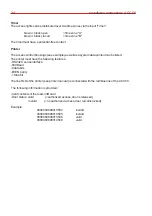
Timer

The access rights can be distributed over two time zones via the input ”Timer”:

brown + black open

= time zone "A"

brown + black closed 

= time zone "B"

The timer must have a potential-free contact.
 

Printer

The access control bookings (see example) as well as a system data printout can be listed.
The printer must have the following features:
-RS 232 C serial interface
-600 Baud
-8 data bits
-EVEN parity
-1 Stop bit

The line RxD of the printer (see printer manual) is connected with the red/blue line of the ACC 50.

 The following information is provided::

-Card contents of the read-in ID card
-Door status: valid            (= authorized access, door is released)
                      invalid          (= no authorized access, door remains locked)

Example:

0000060808010504

invalid

0000060808010505

invalid

0000060808010506

valid

0000060808010508

valid

Содержание ACC 50

Страница 1: ...Änderungen vorbehalten P31050 02 002 03 26 02 2007 Installationsanleitung ACC 50 Art Nr 026389 00 026389 10 Zutrittskontrollsystem für bis zu 99 berührungslose Karten GB D ...

Страница 2: ...rgeregelten vom Netz galvanisch getrennten Lötkolben ausgeführt werden VDE Sicherheitsvorschriften sowie die Vorschriften des örtlichen EVU beachten Gefahr Das Gerät darf nicht in explosionsgefährdeten Räumen oder in Räumen mit metall und kunststoffzersetzenden Dämpfen eingesetzt werden Entsorgung Die Verpackung ist aus folgenden wiederverwertbaren Stoffen hergestellt Pappe Polystyrol PS Polyäthyl...

Страница 3: ...den können Beispiel Zeitzone A 07 00 Uhr 19 00 Uhr Schalter geöffnet Zeitzone B 19 00 Uhr 07 00 Uhr Schalter geschlossen Je nach Zuordnung erhalten bestimmte Personen nur in Zeitzone A nur in Zeitzone B oder in beiden Zeitzonen Zutritt l Die Programmierung des ACC 50 erfolgt durch den Programmierkartensatz Bei der Programmierung des Programmierkartensatzes speichert das ACC 50 die Nummer der Progr...

Страница 4: ... Ø Drucker 5m LifYCY 5x2x0 6mm Ø 2 Spannungsversorgung nach Berechnung H03VV F 2x1 5mm 3 3 Befestigung des ACC 50 Die Befestigungsbohrungen des ACC 50 sind so ausgelegt daß die Montage direkt über einer uP Installationsdose oder Hohlwandinstallationsdose Ø60mm erfolgen kann Das Gerät kann auch direkt über einen Leerrohrausgang montiert werden siehe nachfolgende Zeichnungen Dabei ist eine Kabelrese...

Страница 5: ... die Montage im Außenbereich empfehlen wir Ihnen den Einsatz des beiliegenden Montagesockels 022197 Bei einer Montage mit Montagesockel besteht die Möglickeit des seitlichen oder vertikalen Kabelabgangs für eine aP Verlegung des Anschlußkabels Nach Beendigung der Installation ist die beiliegende selbstklebende Decorfolie anzubringen wodurch die Befestigungsschrauben verdeckt werden ...

Страница 6: ...nungsleitungen müssen abgeschirmt sein Bei Verwendung von Türöffnern ohne Rückmeldekontakt muss violett nach schwarz gebrückt werden rot rosa weiß grau violett schwarz Türöffner relais Alarm relais Wird ein Ruhestrom Türöffner verwendet so wird anstelle der grauen Leitung die rosa Leitung angeschlossen Arbeitsstrom Türöffner mit Rückmeldekontakt und Freilaufdiode grün braun blau grau rosa rot blau...

Страница 7: ... so wird beim Verlassen des Raumes der Türüberwachungskontakt betätigt und somit das Alarmrelais angesteuert In diesem Fall sollte der Türüberwachungskontakt nicht benutzt werden externer Türöffnertaster Wird ein externer Türöffnertaster benötigt wird dieser an der grünen und der schwarzen Leitung angeschlossen Mit dem externen Türöffnertaster kann die Tür freigegeben werden Besucher Er ermöglicht...

Страница 8: ...kt werden Der Drucker muss hierzu folgende Merkmale aufweisen serielle RS 232 C Schnittstelle 600 Baud 8 Datenbits EVEN Parity 1 Stopbit Die Leitung RxD des Druckers siehe Handbuch des Druckers wird mit der rot blauen Leitung des ACC 50 verbunden Sie erhalten Angaben über Karteninhalt der eingelesenen ID Karte Türstatus valid zutrittsberechtigt Tür wird freigegeben invalid keineZutrittsberechtigun...

Страница 9: ...ehmens sind Unikate Jede existierende Karte besitzt eine andere Dateninformation 7 Bedeutung des Programmierkartensatzes Der Programmierkartensatz besteht aus 3 Karten RESET Karte PROGRAM Karte CLEAR Karte Mit diesen Karten können Sie in den jeweiligen Modus des ACC 50 wechseln Der Programmierkartensatz wird vom Errichter programmiert siehe Erstellen des Programmierkartensatzes RESET Karte Achtung...

Страница 10: ...tig die Betriebsspannung damit die Schalteränderung wirksam wird 4 Nach Anlegen der Betriebsspannung leuchtet die gelbe und die rote LED Warten Sie bis die rote LED erloschen ist ca 10 Sekunden Das ACC 50 ist jetzt zur Programmiersatzerstellung bereit 5 RESET Karte ins Feld bringen Grüne LED leuchtet kurz PROGRAM Karte ins Feld bringen Grüne LED blinkt kurz CLEAR Karte ins Feld bringen Rote LED bl...

Страница 11: ...Schalter 1 2 Mit den DIP Schaltern 1 2 kann gewählt werden wie lange das Türöffner Relais angezogen bleibt nach dem eine berechtigte Karte gelesen wurde bzw der externe Türöffnertaster betätigt wurde DIP Schalter 3 4 Mit den DIP Schaltern 3 4 wird die Überwachungszeit eingestellt Ist nach Ablauf der Überwachungszeit der Rückmeldekontakt noch geöffnet wird das Alarmrelais angesteuert Soll der Rückm...

Страница 12: ...st betriebsbereit 11 Betriebsanzeigen LED gelb gelb gelb rot grün blinkt im 2 Sekun dentakt blinkt schnell leuchtet für mehrere Sekunden leuchtet ca 2 Sek LED Funktion Bedeutung Gerät ist im Normalbetrieb leuchtet dauernd ID Karte ist nicht berechtigt Freigaberelais ist angezogen Gerät ist bereit zur Erstellung des Programmierkartensatzes oder Speicher muss noch mit RESET Karte gelöscht werden Ers...

Страница 13: ...e Karte 1 nur in der Zeitzone A und die Karte 2 ist nur in Zeitzone B berechtigt Die Karte 3 ist dagegen in beiden Zeitzonen berechtigt Das ACC 50 legt beim Berechtigen einer Karte diese in dem Zeitzonenspeicher ab der momentan durch die Schalterstellung ausgewählt ist Eine Karte die in beiden Zeitzonen berechtigt sein soll muss folglich zweimal berechtigt werden nämlich bei offenem und geschlosse...

Страница 14: ...ID Karte sperren Öffnen oder schließen Sie den Schalter der Zeitschaltuhr entsprechend der gewünschten Zeitzone A oder B Um das ACC 50 in den Sperrmodus zu schalten bringen Sie die CLEAR Karte ins Feld Der Sperrmodus wird ebenfalls durch schnelles Blinken angezeigt Die zu sperrende Karte ins Feld bringen Bei korrektem Sperrvorgang leuchtet die rote LED ca 1 Sekunde lang auf Sämtliche berechtigten ...

Страница 15: ...bezeichnung 1002 12 0 5 Ausgangsspannung 1 12V DC stabilisiert Ausgangsspannung 2 12V DC nicht stabilisiert nicht geglättet Es kann ein Gesamtstrom Summe beider Ausgänge von max 500mA entnommen werden Beispiel Ausgang 1 100mA Ausgang 2 400mA 151 5 mm 131 mm 18 mm 79 mm Gehäusetiefe 45mm ...

Страница 16: ... C Lagerungstemperaturbereich 35 C 70 C Umweltklasse gemäß VdS Klasse III Abmessungen BxHxT siehe Seite 4 Gewicht ca 200 g Farbe ähnlich RAL 9002 grauweiß Das Gerät entspricht bei bestimmungsgemäßer Anwendung den grundlegenden Anforderungen gemäß Artikel 3 der R TTE Richtlinie 1999 5 EG Die EG Konformitätserklärung steht auf unserer Homepage im Service Downloadbereich zum Download bereit Honeywell...

Страница 17: ...Subject to change without notice Installation Instructions ACC 50 Item no 026389 00 026389 10 Access control system for up to 99 contactless ID cards GB D P31050 02 002 03 26 02 2007 ...

Страница 18: ...diagram 5 Connecting external components 6 Handling ID cards 7 Programming card set 8 Creating programming card set 9 Setting of DIP Switches 10 Initial commissioning 11 Operating displays 12 Time zones 13 Authorize disable ID cards 14 Accessories 14 1 Power supply unit 15 Technical data 16 EC Declarartion of Conformity Contents Page Soldering and connection work should only be carried out when th...

Страница 19: ...e ID cards can be allocated Example Time zone A 07 00 h 19 00 h switch open Time zone B 19 00 h 07 00 h switch closed Depending on the allocation specific persons only receive access in time zone A or time zone B or in both time zones The ACC 50 is programmed with the progarmming card set When programming the programming card set the ACC 50 stores the number of the programming cards once Other pro...

Страница 20: ... 6 Printer 5m LifYCY 5x2x0 6 2 Voltage supply Calculation H03VV F 2x1 5mm 3 3 Fixation of ACC 50 The fixing boreholes of the ACC 50 are designed so that for installation either a flush mounted box or cavity wall installation box 60mm can be used The device can also be installed directly above an empty pipe output see drawing next page taking into consideration that the reserve cable is either in t...

Страница 21: ...ion Installation variations ACC 50 Adapter base Deco foil For outdoor installation we recommend the usage of the including adapter base item no 022 197 Using the adapter base for surface mounted installation the connection lead can either be vertical or lateral After finishing the installation the set screws have to be covered by the self adhesive deco foil ...

Страница 22: ...thout monitoring contact the violet line must be bridged to the black line red pink white grey violet black Door opener relay Alarm relay If a no load current door opener is being used the pink line is connected instead of the grey line Strike with load current function with monitoring contact and free wheeling diode Observe connection polarity green brown blue grey pink red blue Item no 094 051 M...

Страница 23: ...r handle the door monitoring contact is activated when the room is exited and the alarm relay actuated In this case the door monitoring input should not be used External door strike key If an external door strike key is required this is connected to the green and the black line The door can be released with the external door strike key visitors In that case it is also possible to exit the room wit...

Страница 24: ...t can be listed The printer must have the following features RS 232 C serial interface 600 Baud 8 data bits EVEN parity 1 Stop bit The line RxD of the printer see printer manual is connected with the red blue line of the ACC 50 The following information is provided Card contents of the read in ID card Door status valid authorized access door isreleased invalid noauthorized access door remainslocke...

Страница 25: ...attern which is received by the ACC 50 All contactless cards offered by our comany are unique Every existing card contains different data information 7 Programming card set The programming card set comprises 3 cards RESETcard PROGRAM card CLEARcard The actual mode of the ACC 50 can be switched to using these cards The programming card set is programmed by the installer see Creating the programming...

Страница 26: ... voltage the yellow and the red LED light up Wait until the red LED has gone out approx 10 seconds The ACC 50 is now ready to create a programming set 5 Move the RESET card into the field Green LED lights up briefly Move the PROGRAM card into the field Green LED flashes briefly Move the CLEAR card into the field Red LED flashes briefly 6 Move the DIP switches to the normal setting again see 9 Sett...

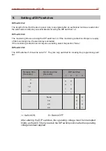
Страница 27: ...ry of the monitoring time the alarm relay is actuated If the monitoring contact does not require evaluating select the position None DIP switch 5 8 The DIP switches 5 8 must be set at 0 They are only switched for creating the programming card set 1 Switch ON 0 Switch OFF After altering the DIP switches the operating voltage must be interrupted briefly as theACC 50 only reads in the DIP switch posi...

Страница 28: ... the device is ready to operate LED yellow yellow yellow red green Flashes every 2 seconds Flashes quickly Lights up for several seconds Lights up for approx 2 sec LED Function Meaning Device is in normal operation Permanently lit up ID card is not authorized Release relay is energized Device is ready for creating the programming card set or memory must still be cleared with the RESET card initial...

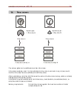
Страница 29: ...thorized in time zone A and card 2 only in time zone B Card 3 on the other hand is authorized in both time zones When authorizing a card the ACC 50 stores the same in the time zone memory which is currently activated due to the switch position A card which requires authorizing for both time zones must therefore be authorized twice i e when the switch is open and closed Memory requirements For both...

Страница 30: ...de Disable ID cards Open or close the switch of the timer according to the desired time zone A or B In order to switch the ACC 50 to disable mode move the CLEAR card into the field The disable mode is also displayed by rapid flashing Move the card which requires disabling into the field If the disabling process is correct the red LED lights up for approx 1 second All authorized ID cards which are ...

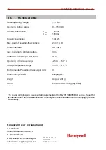
Страница 31: ... 12 0 5 Output voltage 1 12V DC stabilized Output voltage 2 12V DC not stabilized not smoothed A total current total of both outputs of max 500mAcan be used Example Output 1 100mA Output 2 400mA 151 5 mm 131 mm 18 mm 79 mm Housing depth 45mm 14 Accessories 14 1 Power supply unit ...

Страница 32: ...ge 25 C 60 C Storage temperature range 35 C 70 C Environmental Protection Class as per VdS III Dimensions WxHxD see page 22 Weight Approx 200 g Colour similar to RAL 9002 grey white The device complies with the essential requirements of the R TTE 1999 5 EC Directive if used for its intended use The EC Declaration of Conformity can be downloaded from our homepage Service Download Honeywell Security...

Отзывы: