GB-6
D
GB
F
NL
I
E
Restrictors
▷
The appropriate restrictors are to be fitted in the
supply lines for fuel gas, combustion air and
motive air for the eductor to adjust the burner.
Central air connection for LPG operation
▷
The LPG version of the burner has an additional
central air lance.
▷
The gas lance must be cooled to prevent the
gas cracking and soot forming inside the burner.
▷
The connection is made with an Ermeto pipe.
▷
The purge air connection must be located in the
air supply line to the burner upstream of the air
control valve, for example at the inlet of the air
solenoid valve.
▷
Open the adjuster in the central air lance fully;
on ECOMAX
®
1, the adjuster must be restricted
to 45° or 50%.
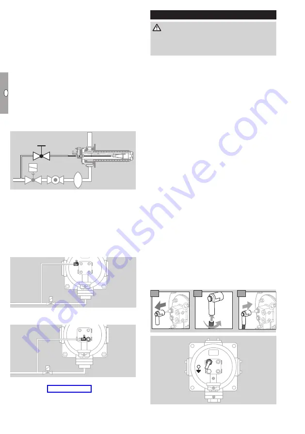
Purge air connections for electrode and UV
sensor
▷
The electrode and the UV sensor should be
cooled and purged with air.
▷
The air must be branched off upstream of the
air control valve, for example at the inlet of the
air solenoid valve.
▷
Connect the purge air to the gas flange next to
the electrode.
▷
In the case of UV control, use the purge air con-
nection of the UV sensor.
▷
The nozzles are adapted to the relevant burner,
see page 16 (Accessories). The nozzles do
not need any adjustment.
Wiring
DANGER
Electric shocks can be fatal! Before working on
possible live components, ensure the unit is discon-
nected from the power supply.
▷
The flame is monitored by a combined flame
rod/spark electrode as standard on the burner
ECOMAX
®
.
▷
Flame control with a UV sensor is necessary if a
furnace temperature of 1050°C is exceeded for
direct heating or 950°C for indirect heating. In
this case, we recommend a UV sensor UVS 10
with a purge air connection be used.
▷
An adapter set (Order No. 21800791), which
must be ordered separately, is available for in-
stalling the UVS 10. If the adapter set has been
ordered with the burner, it is fitted to the burner
on delivery and the UV sensor can be screwed
on to it.
▷
For high temperature operation without flame
control using ionization or a UV sensor, the air
flow must be monitored by a pressure switch.
▷
We recommend an ignition transformer ≥ 7.5 kW,
≥ 20 mA.
▷
For the ignition/ionization cable, use (unscreened)
high-voltage cable:
FZLSi 1/6 up to 180°C (356°F),
Order No. 04250410, or
FZLK 1/7 up to 80°C (176°F),
Order No. 04250409.
▷
Length of cable: max. 5 m, recommended < 1 m.
▷
Lay cable individually and not in a metal conduit.
▷
Install cable well away from mains cables and
interference from electro-magnetic sources.
▷
In particular, avoid external electrical interference
when using ionization control.
▷
For UV control, route the ignition cable separately
from the UV cable.
1
3
2


