


BODY PANELS/EXHAUST SYSTEM
2-10
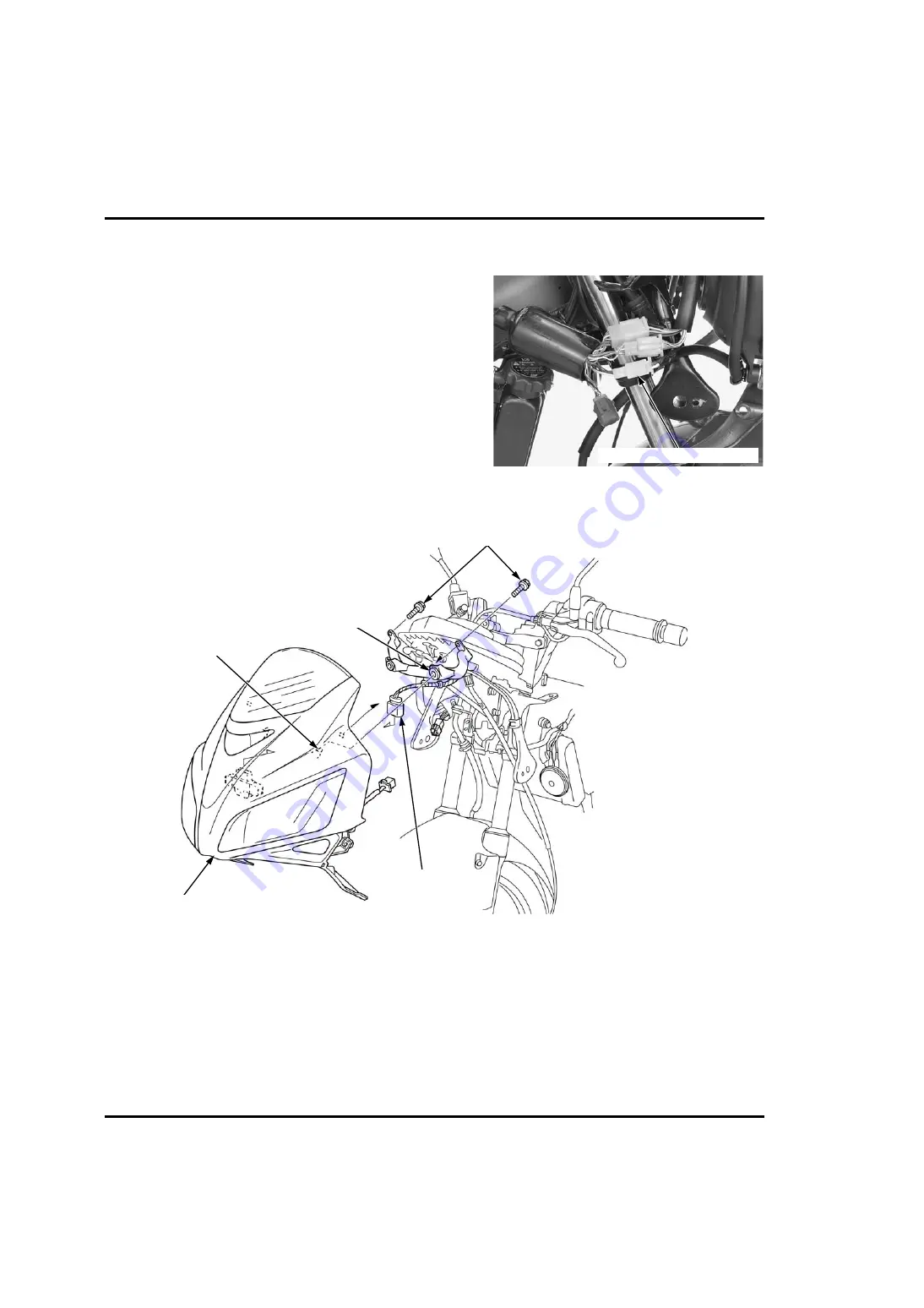
UPPER COWL
REMOVAL/INSTALLATION
Remove the middle cowl (page 2-9).
Disconnect the headlight/position light 4P (Natural)
connector.
Remove the bolts and release the bosses from the
grommets of the upper cowl stay.
Disconnect the bank angle sensor 3P (Gray) connector.
4P (NATURAL) CONNECTOR
BOLTS
GROMMET
BOSS
3P (GRAY) CONNECTOR
UPPER COWL
Содержание CBR125R
Страница 38: ...MEMO...
Страница 56: ...MEMO...
Страница 84: ...MEMO...
Страница 94: ...FUEL SYSTEM PGM FI 5 2 FUEL SYSTEM PGM FI COMPONENT LOCATION 1 2 N m 0 1 kgf m 0 9 lbf ft...
Страница 213: ...9 1 9 9 CYLINDER PISTON COMPONENT LOCATION 9 2 SERVICE INFORMATION 9 3 TROUBLESHOOTING 9 3 CYLINDER PISTON 9 4...
Страница 214: ...CYLINDER PISTON 9 2 CYLINDER PISTON COMPONENT LOCATION...
Страница 224: ...MEMO...
Страница 248: ...ALTERNATOR STARTER CLUTCH 11 2 ALTERNATOR STARTER CLUTCH COMPONENT LOCATION 64 N m 6 5 kgf m 47 lbf ft...
Страница 260: ...CRANKSHAFT BALANCER TRANSMISSION 12 2 CRANKSHAFT BALANCER TRANSMISSION COMPONENT LOCATION...
Страница 282: ...MEMO...
Страница 392: ...MEMO...
Страница 416: ...MEMO...
Страница 417: ...20 1 20 20 WIRING DIAGRAMS ED E F II G type 20 3 CM type 20 4 U type 20 5...
Страница 428: ...MEMO...


