Home Depot 1002269802 Скачать руководство пользователя страница 1


Item #1002269802

USE AND CARE GUIDE

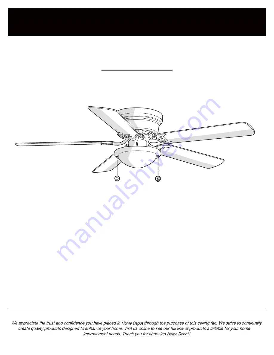
HUGGER 52 IN. CEILING FAN

Model #AL383LED-BN

1-877-527-0313

HOMEDEPOT.COM

THANK YOU

THANK YOU


Questions, problems, missing parts? Before returning to the store call  

Home Depot Customer Service 

8 a.m. - 7 p.m., EST, Monday-Friday, 9 a.m. - 6 p.m., EST Saturday 

Содержание 1002269802

Страница 1: ...GER 52 IN CEILING FAN Model AL383LED BN 1 877 527 0313 HOMEDEPOT COM THANK YOU THANK YOU Questions problems missing parts Before returning to the store call Home Depot Customer Service 8 a m 7 p m EST Monday Friday 9 a m 6 p m EST Saturday ...

Страница 2: ...ncluded Package Contents Installation Assembly Hanging the Fan Attaching the Fan Blades Installing the Light Kit 2 3 4 4 4 4 5 6 7 8 8 11 12 Operation Pull Chain Operating Instructions Reverse Switch Operating Instructions Care and Cleaning Troubleshooting Service Parts 14 14 14 15 15 17 Table of Contents ...

Страница 3: ...ian 3 The outlet box and support structure must be securely mounted and capable of reliably supporting a minimum of 35 lbs 15 9 kg or less Use only UL listed outlet boxes marked FOR FAN SUPPORT 4 The fan must be mounted with a minimum of 7 ft 2 1m clearance from the trailing edge of the blades to the floor 5 Avoid placing objects in the path of the blades 6 To avoid personal injury or damage to th...

Страница 4: ...wobble is normal and should not be considered a defect Servicing performed by unauthorized persons shall render the warranty invalid There is no other express warranty We hereby disclaim any and all warranties including but not limited to those of merchantability and fitness for a particular purpose to the extent permitted by law The duration of any implied warranty which cannot be disclaimed is l...

Страница 5: ...ssembled Blade arm screw and lock washer Light kit mounting screw preassembled Light holder thumbscrew preassembled 9 5 watt LED bulb not to scale Plastic plug not to scale Pull chain and fob not to scale Part Part Description Description 16 3 5 4 11 3 4 1 1 2 Quantity Quantity 5 NOTE Hardware shown to actual size unless noted otherwise in the table below HOMEDEPOT COM Please contact 1 877 527 031...

Страница 6: ...F G Description Description Blade arm Light kit Glass shade Pre Installation continued 6 Part Part A B C D Quantity Quantity 1 1 1 5 Description Description Mounting plate Fan motor assembly Motor housing Blade Quantity Quantity 5 1 1 A B C F G D E ...

Страница 7: ...its bracing must be able to fully support the weight of the moving fan at least 35 lbs Do not use a plastic outlet box The illustrations below show two different ways to mount the outlet box KK not included WARNING To reduce the risk of fire electric shock or personal injury mount the fan to an outlet box marked acceptable for fan support using the screws provided with the outlet box An outlet box...

Страница 8: ...nting plate A is tight and secured WARNING To reduce the risk of fire electric shock or other personal injury mount the fan only to an outlet box or supporting system marked acceptable for fan support and use the mounting screws provided with the outlet box Carefully lift the fan motor assembly B and insert the T section of the motor mounting plate MM into the slot in the mounting plate A 2 A KK 8...

Страница 9: ...ecure the wire nuts BB with electrical tape Make sure there are no loose strands or connections Connect the ground conductor of the 120V supply this may be a bare wire or a wire with green colored insulation to the green ground lead s of the fan Connect the fan motor white wire to the supply white neutral wire using a plastic wire nut BB Connect the fan motor black wire and the blue wire to the su...

Страница 10: ...M to the mounting plate A with the screws and lock washer CC provided 5 Attaching the motor housing to the mounting plate Carefully lift the motor housing C onto the mounting plate A properly align the holes and tighten the motor housing C with the four screws and lock washer DD supplied 10 Assembly Hanging the Fan continued C DD A A MM CC CC B ...

Страница 11: ...iber washers AA Start a screw and fiber washer AA into the blade arm E but do not tighten Repeat for the two remaining blade attachment screws and fiber washers AA Tighten each screw securely starting with the center screw Make sure the blade D is straight Repeat these steps for the remaining blades D Align motor holes to blade arms E and secure with screws and lock washer EE provided tighten scre...

Страница 12: ...crews FF provided Be sure to tighten all screws Installing the light bulb and glass shade CAUTION Before starting installation disconnect the power by turning off the circuit breaker or removing the fuse at the fuse box Turning power off using the fan switch is not sufficient to prevent electric shock 12 Install 1 x 9 5W Medium base LED bulb HH included Mount the glass shade G to the light kit F b...

Страница 13: ...ued Disassemble the switch housing cover NN from the light kit F You can keep the light kit F for future use Attach the plastic plug II to the switch housing cover NN Install the switch housing cover NN to the switch housing with light kit mounting screws FF provided 10 Installing the fan without the light kit optional ...

Страница 14: ...ched to the switch housing OO Operation JJ JJ OO NOTE Wait for the fan to stop before reversing the direction of the blade rotation REVERSE SWITCH OPERATING INSTRUCTIONS REVERSE SWITCH OPERATING INSTRUCTIONS The reverse switch is located on the surface of the switch housing This switch controls directions forward switch down or reverse switch up Warm weather Counterclockwise Direction A downward a...

Страница 15: ...in the switch housing Make sure all motor housing screws are snug Make sure the screws that attach the fan blade arm to the motor hub are tight Make sure the wire nut connections are not rattling against each other or the interior wall of the switch housing Allow a 24 hour breaking in period Most noises associated with a new fan disappear during this time If using the ceiling light kit make sure t...

Страница 16: ...ling above the tip of one of the blades then select any fan blade and measure from the center of the selected blade to the point on the ceiling Rotate the fan until the next blade is positioned and repeat the measurement using the same point from the ceiling for every blade Measurement deviations should be within 1 8 in If all deviations are less than 1 8 in and the fan continues to wobble please ...

Страница 17: ...shade Part Part AA BB CC DD EE FF GG HH II JJ Description Description Blade attachment screw and fiber washer Plastic wire nut Mounting plate screw and lock washer Motor housing screw and lock washer preassembled Blade arm screw and lock washer Light kit mounting screw preassembled Light holder thumbscrew preassembled 9 5 watt LED bulb Plastic plug Pull chain and fob A F G B C D E AA GG JJ II HH B...

Страница 18: ...anual for future use AL383LED002 A 1 877 527 0313 HOMEDEPOT COM Questions problems missing parts Before returning to the store call Home Depot Customer Service 8 a m 7 p m EST Monday Friday 9 a m 6 p m EST Saturday ...

Отзывы: