


10
Assembly - Hanging the Fan (continued)
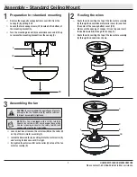
Wiring the fan to the receiver
□
If using the 6 in. ball downrod assembly (B) provided, wire
the receiver to the fan wires by connecting the molded
adaptor plug from receiver (J) with molded adaptor of the
fan motor assembly (E) together.
□
If you wish to use longer downrod, you can use the
extension lead wire (L or M) provided by connecting the
molded adaptor together.
5
NOTE:
The fan comes with 12 in. lead wires for use with the
provided 6 in. ball downrod assembly (B), if you wish to use
longer downrod, you can use the extension lead wire (42 in.) (M)
provided.
Outlet box
in the ceiling
(MM)
Green
L
N
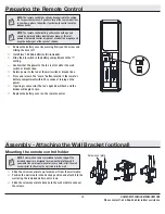
Mounting the fan-motor assembly
□
Align the locking slots of the canopy (C) with the two
screws (CC) and alignment post (KK) in the mounting
bracket (A).
□
Push up the canopy (C) and turn it clockwise until the
alignment post (KK) engages to the round hole and the
screws (CC) engage to the key slots.
□
Firmly tighten the two mounting screws (CC).
□
Align the oval shape on the canopy (C) with canopy bottom
cover (DD).
□
Push up the canopy bottom cover (DD) until the screw (CC)
heads engage to the slots on the canopy bottom cover (DD)
so that the magnetic canopy bottom cover (DD) can be
attached to the bottom of the canopy (C) properly.
6
WARNING:
When using the standard ball/downrod mounting,
the tab in the ring at the bottom of the mounting bracket
must rest in the groove of the hanger ball. Failure to properly
seat the tab in the groove could cause damage to the wiring.
E
D
DD
C
A
CC
KK