ENGLISH | 13
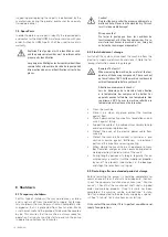
Risk of electrocution!
Improper use of electricity can be fatal! All pumps
with exposed cable ends must be connected by a
qualified electrician.
Risque d’électrocution !
Une mauvaise utilisation de l’électricité peut être fa-
tale ! Toutes les pompes dont les extrémités de câble
sont exposées doivent être raccordées par un élec-
tricien qualifié.
All electrical work shall be carried out under the super-
vision of an authorized, licensed electrician. The present
state adopted edition of the National Electrical Code as
well as all local codes and regulations shall be complied
with.
5.6.1 Verification of power supply
Prior to making any electrical connections or applying pow-
er to the pump, compare the power supply available at the
pump station to the data on the unit‘s nameplate. Confirm
that both voltage and phase match between pump and
control panel.
5.6.2 Power lead wiring
Please refer to wiring diagram in the appendix for specific
connection details.
The pump must be connected electrically through a motor
starter with proper circuit breaker protection in order to
validate warranty. Do not splice cables.
5.6.3 Thermal switch wiring
Pumps are equipped with thermal switches embedded
in the stator windings which are normally closed, auto-
matically resetting switches. Switches will open when the
internal temperature rises above the design temperature,
and will close when the temperature returns to normal.
Thermal switches must be wired to a current regulated
control circuit in accordance with the NEC. Identify ther-
mal switch leads marked T1 and T2 in the power cable.
The resistance across the leads will be 0.5 Ohms. Thermal
leads must be connected to the thermal overload relay
located in the control panel. Thermal switch leads must be
connected to validate warranty.
Note: All sizes of Class 1, Div. 1 pumps for hazardous
service must have thermal switch leads connected to
a current regulated control circuit in accordance with
NEC.
5.6.4 Seal probe wiring
The mechanical seal leak detector probe utilized in the
pump is a conductive probe which is normally open. The
intrusion of water into the seal chamber completes the
electrical circuit. Control panel provisions will sense this
circuit closure, and will provide indication or alarm func-
tions depending on the panel design.
Either single or dual wire systems may be provided. Sin-
gle wire systems utilize one energizing conductor, and
the pump casing and neutral lead as the ground or return
portion of the circuit. The dual wire systems utilize two
separate conductors for each leg of the circuit.
With either system, the seal probe leads must be wired
into a control circuit provided in the control panel. This
control circuit must energize the probe with a regulated
power source, and sense the closed circuit in event of wa-
ter intrusion Indication and alarm functions must also be
provided in the control circuit. Please see control panel
wiring diagram for seal probe connection points.
For Hazardous Area Classification Pumps, leak de-
tector circuit must be in conformance with applica-
ble NEC codes and regulations.
Pour les pompes classées en zone dangereuse, le
circuit du détecteur de fuites doit être conforme aux
codes et réglementations NEC applicables.
5.6.5 Start / Run Capacitors and Relays
All single phase motors require start and run capacitors
along with a start relay to operate. Capacitors and relays
must be sized for the specific motor. Capacitors are sized
based on ideal conditions. The run capacitor may need to
be resized to match the available field voltage. Each cap
kit shipped is supplied with a wiring diagram and start up
procedure.
5.6.6 Single Phase Pump Start-Up Procedure
Run Capacitor sizing can vary depending on the incoming
supply voltage provided. HOMA Single Phase pumps are
provided with Start and Run Capacitor(s) sized for 220-
230V under load. Frequently, the available line voltage is
considerable different than indicated, and the Run capac-
itor(s) may need to be resized to match the available field
voltage. The following procedure will allow you to verify
proper operation of your single phase pump, and/or make
necessary changes to you capacitors to correct for your
power supply. After verifying wiring is in accordance with
your pump requirements, start pump and record the fol-
lowing readings from each of the (3) pump cable leads.
Current under load:
U1________Amps>U2________Amps>Z2_______Amps
Should be (highest rating) (middle rating) (lowest rating)
Lead U1 (common) should have the highest current read-
ing. Lead Z2 (start) should have the lowest reading.
If Z2 current draw is greater than the current draw of ei-
ther U1 or U2, a smaller size Run capacitor (lower micro-
farad rating) is required to correct the condition. Example:
If a 60 µf Run capacitor was supplied, change to a 50 µf
Run capacitor and check current readings. Typically, only
one step down in capacitor size is required, but in certain
instances 2 steps may be required.
( ) The standard capacitor kit provided includes:
__µf start capacitor
__µf run capacitor.
( ) Additional run capacitors have been included for use in
tuning the pump to match available line voltages for opti-
mum performance.
__µf run capacitor
__µf run capacitor
__µf run capacitor
Содержание TP30-70
Страница 1: ...Installation Operation and Maintenance Manual TP30 70 Version 11 2021 ...
Страница 22: ...22 ENGLISH Notizen Notes ...
Страница 23: ...ENGLISH 23 ...


