background image

TRANSPORT 


HOLZMANN MASCHINEN GmbH   www.holzmann-maschinen.at 

 49


ED1080ADIG


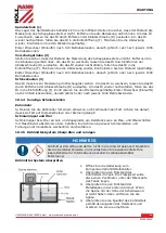
W A R N I N G  


Such a safety instruction indicates a potentially hazardous situation which, if not 

avoided, may result in serious injury or even death. 


C A U T I O N  


A safety instruction designed in this way indicates a potentially hazardous situation 

which, if not avoided, may result in minor or moderate injury.


N O T I C E  


A safety notice designed in this way indicates a potentially hazardous situation which, 

if not avoided, may result in property damage.


15.8


Residual risks 


Formation of a flow chip 

-


This wraps around the forearm and causes severe cuts. 


Throwing away workpieces or tools at high speed. 

-


Always check workpieces for suitability and clamp them securely and firmly 

-


Clamp and center longer workpieces via an additional counter bearing (e.g. tailstock) 

-


For very long workpieces, use a steady rest 


Risk of tripping due to supply lines on the floor. 

-


Properly route supply lines and cables 

-


Mark unavoidable tripping hazards yellow-black 

Irrespective of all safety regulations, your common sense and appropriate technical 

suitability/training are and will remain the most important safety factor for error-free operation of 

the machine. Safe working primarily depends on you! 

16


TRANSPORT 

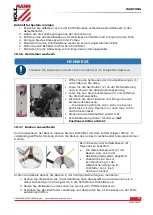
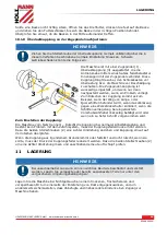
W A R N I N G  


Damaged or insufficiently strong hoists and load slings can result in serious injury or 

even death. Before use, therefore, check hoists and load slings for adequate load-

bearing capacity and perfect condition. Secure the loads carefully. Never stand under 

suspended loads! 


To ensure proper transport, observe the instructions and information on the transport packaging 

regarding  centre  of  gravity,  attachment  points,  weight,  means  of  transport  to  be  used  and  the 

prescribed transport position, etc. 
Transport the machine in its packaging to the place of installation. To manoeuvre the machine in 

the packaging, a pallet truck or forklift truck with the appropriate lifting force can be used, for 

example. Ensure that the selected lifting equipment (crane, forklift, pallet truck, load sling, etc.) 

is in perfect condition. Lifting and transporting the machine may only be carried out by qualified 

personnel with appropriate training for the lifting equipment used. 


Содержание ED1080ADIG

Страница 1: ...Edition 15 09 2020 Revision 00 EcC DE EN ED1080ADIG Originalfassung DE BETRIEBSANLEITUNG METALLDREHMASCHINE bersetzung Translation EN USER MANUAL METAL TURNING LATHE...

Страница 2: ...NTAGE 16 7 1 Vorbereitende T tigkeiten 16 7 1 1 Lieferumfang pr fen 16 7 1 2 Reinigen und abschmieren 16 7 1 3 Anforderungen an den Aufstellort 16 7 1 4 Verankerungsfreie Montage 17 7 1 5 Verankerte M...

Страница 3: ...38 10 1 Instandhaltungs und Wartungsplan 39 10 1 1 Nachstellen der Keilleisten 39 10 1 2 Sichtkontrolle der lst nde 39 10 1 3 lwechsel Spindelstock Vorschubgetriebe und Schlosskasten 40 10 1 4 Sonsti...

Страница 4: ...ush button 61 18 4 Setting spindle speed and rotation direction 61 18 4 1 Spindle speed selection 61 18 4 2 Direction of rotation 62 18 4 3 Running operation 62 18 5 Threads and feeds 62 18 5 1 Change...

Страница 5: ...0 1 7 Replacing jaws 76 20 1 8 Adjusting the overload clutch on the feed spindle 76 21 STORAGE 77 22 DISPOSAL 77 23 TROUBLESHOOTING 77 24 SCHALTPLAN WIRING DIAGRAM 79 25 ERSATZTEILE SPARE PARTS 80 25...

Страница 6: ...ausschalten und Netzstecker ziehen EN Switch off the machine before repairing servicing or stopping work and pull out the mains plug DE Pers nliche Schutzausr stung tragen EN Wear personal protective...

Страница 7: ...z hex key set 17 Camlock Bolzen 6 Stk camlock bolts 6 pcs 7 Wechselzahnr der Gewindeuhr Z 14 15 change gears thread dial indicator T 14 15 18 Spannbacken Set f r 3 Backenfutter set of reverse jaws for...

Страница 8: ...st 20 Gewindeduhr thread dial indicator 7 Arbeitsleuchte work lamp 21 Einr ckhebel Gewindeschneiden Schlossmutter shift lever tapping lock nut 8 Schnellwechselhalter quick change tool post 22 Einr ckh...

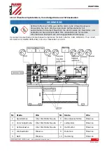
Страница 9: ...us 0 coolant pump On I Off 0 N Handrad Oberschlitten handwheel top slide G NOT AUS Schalter Emergency Stop O Gewindeuhr thread dial indicator H Motorstufen Schalter motor step switch P Einr ckhebel Ge...

Страница 10: ...ldruckpegel LPA sound pressure level LPA 78 dB A k 3dB A DE Hinweis Ger uschangaben Bei den genannten Zahlenwerten handelt es sich um Emissionspegel und nicht notwendigerweise um sichere Arbeitspegel...

Страница 11: ...k nnen Abbildungen und Inhalte geringf gig abweichen Sollten Sie Fehler feststellen informieren Sie uns bitte Technische nderungen vorbehalten Kontrollieren Sie die Ware nach Erhalt unverz glich und v...

Страница 12: ...etreiben der Maschine ohne ad quate k rperliche und geistige Eignung Betreiben der Maschine ohne Kenntnis der Bedienungsanleitung nderungen der Konstruktion der Maschine Verwendung von Schmirgelleinen...

Страница 13: ...enn die Schutzabdeckung angebracht ist Eine Spiralfeder als Schutzabdeckung an der Leitspindel verhindert das Einziehen von Kleidungsst cken Eine berlastkupplung an der Zugspindel 5 4 Allgemeine Siche...

Страница 14: ...acht und der n tigen Vorsicht und wenden Sie auf keinen Fall berm ige Gewalt an berbeanspruchen Sie die Maschine nicht Setzen Sie die Maschine vor Einstell Umr st Reinigungs Wartungs oder Instandhaltu...

Страница 15: ...hsch den f hren kann wenn sie nicht gemieden wird 5 8 Restgefahren Bildung eines Flie spans Dieser umschlingt den Unterarm und verursacht schwere Schnittverletzungen Wegschleudern von Werkst cken oder...

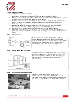
Страница 16: ...ann 2 Heben Sie die Metalldrehmaschine vorsichtig mit Hilfe eines Kranes bzw einer anderen geeigneten Hebeeinrichtung an Empfohlen wird beim Heben mit Gurt Haken zu verwenden Richten Sie die Gurtl nge...

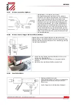
Страница 17: ...ivellieren A Spindelstock B Pr zisionswaage C Reitstock D Sattel und Querschlitten E Bettf hrung 1 Setzen Sie die Stellscheibe 3 unter den Maschinenunterbau 2 Montieren Sie die Stellschrauben 1 3 Rich...

Страница 18: ...4 Nivelliervorgang erforderlichenfalls wiederholen 7 1 6 Zusammenbau Die Maschine kommt vormontiert es sind die zum Transport abmontierten Anbauteile laut nachstehender Anleitung zu montieren und die...

Страница 19: ...sich vor dem ersten Arbeitseinsatz eine berpr fung der Maschinenausrichtung und nivellierung Um die Arbeitsgenauigkeit zu gew hrleisten sollten Ausrichtung und Nivellierung in der Folge in regelm ige...

Страница 20: ...l leicht ein len Dann Drehfutter bis zur Spindelnase anheben und auf die Spindel dr cken Haltenocken Bolzen durch Drehen der Haltenocken entgegen dem Uhrzeigersinn anziehen Nach dem Anziehen sollte d...

Страница 21: ...montierenden Flansch f r das 4 Backenfutter auf Sauberkeit und nicht besch digte Aufnahmefl chen 2 Pr fen Sie ob sich alle Spannbolzen in der Drehspindelaufnahme in ge ffneter Stellung befinden 3 Heb...

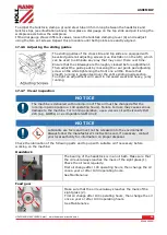
Страница 22: ...h jedes Spiel beseitigen l sst das dort mit der Zeit auftreten kann Sorgen Sie daf r dass die Gleitf hrungen vor ihrer Justierung gr ndlich gereinigt werden Justieren Sie dann die F hrungsleisten inde...

Страница 23: ...triebsstunden danach j hrlich oder nach jeweils 1000 Betriebsstunden Siehe Wartung Schlosskasten Kontrollieren Sie den lstand regelm ig mit Hilfe des Schauglases 3 an der Frontseite Erster lwechsel na...

Страница 24: ...rtet und gef llt ist 2 Positionieren Sie die K hlmitteld se wie gew nscht f r Ihren Betrieb 3 Verwenden Sie den Schalter am Bedienfeld um die K hlmittelpumpe ein bzw auszuschalten 4 Regulieren Sie den...

Страница 25: ...trollieren berpr fen Sie die lst nde und f llen Sie bei Bedarf l nach K hlmittel kontrollieren berpr fen Sie den Stand des K hlmittels und f llen Sie bei Bedarf K hlmittel nach 8 2 Erstinbetriebnahme...

Страница 26: ...gen Sie den Schalthebel Drehrichtung nach unten Die Maschine darf nicht starten Ist das der Fall ist die Sicherheitsfunktion des NOT AUS Schalter gew hrleistet Fahren Sie mit dem n chsten Schritt fort...

Страница 27: ...stet unten leinlass Geschwindigkeit bzw Drehrichtung nicht im laufenden Betrieb ndern Elektrische Spannung Momentlauf Taster Betriebskontrollleuchte NOT AUS Schalter 8 3 2 Maschine einschalten HINWEIS...

Страница 28: ...Werkzeugstandzeit Um die Spindeldrehzahl richtig einzustellen m ssen Sie folgendes tun Die optimale Spindeldrehzahl f r die jeweilige Bearbeitungsaufgabe festlegen und die Maschinensteuerung so einst...

Страница 29: ...werkseitig montierten Wechselr dern einstellen F r spezielle Vorsch be oder Gewindesteigungen m ssen die erforderlichen Wechselr der gewechselt werden WARNUNG Maschine vor Austausch oder Positionsver...

Страница 30: ...ken eines Hebels zu unterst tzen Die Zugspindel wird ber den Wahlhebel Vorschubrichtung B am Spindelstock eingeschaltet und damit die Vorschubrichtung bestimmt Legen Sie den Wahlhebel entsprechend der...

Страница 31: ...festlegen Einr ckhebel Gewindeschneiden Schlossmutter L muss w hrend des Gewindeschneidvorganges immer geschlossen sein Metrisches Gewinde Zollgewinde Einstellungen f r metrische Gewinde T Wechselr d...

Страница 32: ...mit der Leitspindel eingreift Auf der Skalenscheibe der Gewindeuhr sind die nummerierten Striche 1 3 5 und 7 aufgezeichnet Dazwischen befinden sich Striche ohne Nummerierung so genannte Halbstriche We...

Страница 33: ...en den Uhrzeigersinn Drehen Sie den Werkzeughalter in die gew nschte Position und stellen Sie ihn anschlie end durch Drehen des Klemmhebels im Uhrzeigersinn wieder fest 8 7 Montage von L netten Verwen...

Страница 34: ...ine vom Netz 2 Platzieren Sie zum Schutz der pr zisionsgeschliffenen Oberfl chen unter der Spindel ein stabiles Brett oder eine Drehfutter Wiege 3 Setzen Sie den Futterschl ssel in eine Scrollnut ein...

Страница 35: ...ch k nnen nicht zylindrische Teile zum Plandrehen oder Bohren gehalten und in die Spindelmittellinie gebracht werden Ein weiterer Vorteil ist dass der Gro teil der Werkst cke au erhalb der Spindelrota...

Страница 36: ...itsvorkehrungen und das Drehspiel 7 Schieben Sie den Reitstock vom Werkst ck weg und montieren Sie die erforderlichen Reitstockwerkzeuge zum Bohren oder Ausbohren oder positionieren Sie den Mei el zum...

Страница 37: ...g des Werkst cks auf der Spindelkopfseite Die mitlaufende Zentrierspitze sitzt in der Zentrierbohrung des Werkst cks auf der Reitstockseite 8 9 8 Drehen kurzer Kegel mit dem Oberschlitten Das Drehen k...

Страница 38: ...Freischneiden mehr durch 9 REINIGUNG HINWEIS Falsche Reinigungsmittel k nnen den Lack der Maschine angreifen Verwenden Sie zum Reinigen keine L sungsmittel Nitroverd nnung oder andere Reinigungsmittel...

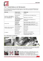
Страница 39: ...f llen Oberschlitten Planschlitten alle Schmiernippel und ler mit Maschinen l abschmieren bzw bef llen J hrlich oder nach jeweils 1000 Betriebsstunden Vorschubgetriebe l wechseln Schlosskasten l wechs...

Страница 40: ...tieren Sie gegebenenfalls Ihre lokale Beh rde f r weitere Informationen bez glich der ordnungsgem en Entsorgung Versorgen Sie Getriebe mit Getriebe l empfohlen f r ISO 12925 1 CKD DIN51517 Teil 3 CLP...

Страница 41: ...ube D auslaufen Um das l wieder nachzuf llen f llen Sie das l in die Einf ll ffnung F Kontrollieren Sie den lstand regelm ig Erster lwechsel Einlauf l nach 100 Betriebsstunden danach j hrlich oder nac...

Страница 42: ...men und bringen Sie den Riemen auf Spannung Die Spannung stimmt wenn sich ein einzelner Keilriemen mit dem Daumen nur noch max 5 mm durchdr cken l sst Ziehen Sie die Stellmuttern wieder fest Schutzabd...

Страница 43: ...chlitten behindert wird wenn das Werkzeug gegen eine Werkst ckschulter kollidiert wenn die Schlittenverriegelung bei einger cktem Vorschubw hlhebel linksseitig bet tigt wird oder wenn ein zu tiefer Sc...

Страница 44: ...e Behebung Maschine startet nicht Maschine ist nicht angeschlossen Sicherung oder Sch tz kaputt Kabel besch digt Sicherheitseinrichtung nicht verriegelt Alle elektr Steckverbindungen berpr fen Sicheru...

Страница 45: ...ucts illustrations and contents may differ slightly If you notice any errors please inform us Technical changes reserved Check the goods immediately after receipt and note any complaints on the consig...

Страница 46: ...mental aptitude Operating the machine without knowledge of the operating instructions Changes in the design of the machine Use of emery cloth by hand Operating the machine outdoors Processing of dust...

Страница 47: ...working with the machine the following points must be observed in addition to the general rules for safe working Before start up check the machine for completeness and function Only use the machine if...

Страница 48: ...tarting Do not work on the machine if it is tired not concentrated or under the influence of medication alcohol or drugs Do not use the machine in areas where vapours from paints solvents or flammable...

Страница 49: ...respective of all safety regulations your common sense and appropriate technical suitability training are and will remain the most important safety factor for error free operation of the machine Safe...

Страница 50: ...and check the machine immediately after unpacking for transport damage or missing or damaged parts Report any damage to the machine or missing parts immediately to your retailer or freight forwarder 1...

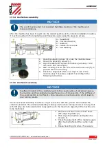
Страница 51: ...er a few days of use of the machine and if necessary adjust it according to the following instructions 17 1 5 Anchored assembly NOTICE Insufficient rigidity of the substrate leads to the superposition...

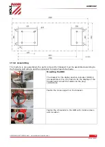
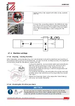
Страница 52: ...according to the following instructions and the connection to mains have to be made Mounting the DRO The bracket for the digital position indicator DRO is pre assembled You only have to fix the displa...

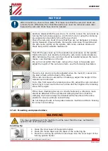
Страница 53: ...alignment and levelling should be repeated at regular intervals To level the machine use a precision spirit level according to DIN 877 with an accuracy of 0 02 mm to 1000 mm This allows the horizonta...

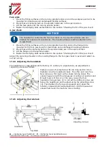
Страница 54: ...is mark remove the chuck or face plate and adjust the height of the cam lock studs see the following illustration The cam lock stud is correctly adjusted when the mark C carved into the stud is flush...

Страница 55: ...are in the open position 3 Lift the flange onto the spindle holder 4 Fasten the clamping bolts as described in the section Checking the fit of the jaw chuck Adjust the centering shoulder on the locat...

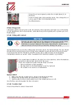
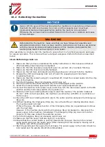
Страница 56: ...ight an adjustment will result in increased wear and heavy jerky running 17 2 7 Visual inspection NOTICE The machine is delivered with running in oil This oil must be changed after the running in peri...

Страница 57: ...peratures occur at the cutting edge of the tool due to the frictional heat The tool should therefore be cooled during turning Cooling with a suitable coolant will improve the work result and prolong t...

Страница 58: ...ded to use a cable type H07RN taking measures to protect against mechanical damage in a current capacity data sheet NOTICE Rotary current machines must always be connected to 3 phases and a protective...

Страница 59: ...coolant pump F is switched off direct the coolant nozzle into the chip tray of the machine 7 Turn the Emergency Stop G clockwise until it pops out 8 Move the selector lever feed direction B to the di...

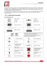
Страница 60: ...oubleshooting section If you cannot find a remedy contact your specialty retailer or customer service 18 3 Operating the machine 18 3 1 Control Icons Main switch I ON 0 OFF Coolant Green On Red Off Ha...

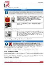
Страница 61: ...essed the main spindle immediately turns forward and stops as soon as you release the button 18 4 Setting spindle speed and rotation direction NOTICE Never change the direction of rotation or speed as...

Страница 62: ...ing or automatic feed is not in use the selector lever feed direction should be in the neutral position to ensure disconnection of the lead screw and the feed screw To avoid unnecessary wear the threa...

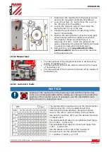
Страница 63: ...lide is carried out by means of handwheel 1 The manual feed of the cross slide is carried out by means of handwheel 2 The manual feed of the top slide is carried out by means of handwheel 3 18 5 3 Aut...

Страница 64: ...tion of rotation for threading left right thread You can set the pitch with the feedrate selectors The shift lever tapping lock nut P must always be closed during the thread cutting process Metric thr...

Страница 65: ...he same turn again at each step On the lower end of the thread dial indicator shaft there are several change gears with different numbers of teeth to be able to turn metric threads with different thre...

Страница 66: ...ngle to the axis of rotation see illustration on the left When clamping at an angle the turning tool can be pulled into the workpiece Align the turning tool in height Use the tailstock with centering...

Страница 67: ...eeve with the clamping lever Use the handwheel to retract and extend the tailstock sleeve 18 8 1 Tailstock laterally offset The transverse displacement of the tailstock is necessary for example when t...

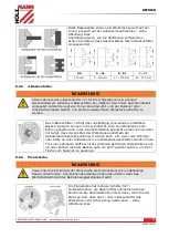
Страница 68: ...iguration is used to hold concentric workpieces that are centred with the same pressure from all three jaws A set of reversible top jaws is also included to allow additional workpiece configurations B...

Страница 69: ...the quill when enough pressure is applied to hold the workpiece Additional support may be required depending on the workpiece 5 Clamp the workpiece in at least three locations as evenly spaced as poss...

Страница 70: ...onto the workpiece The driving pin which is screwed into the chuck flange transmits the torque to the rotary heart The fixed centering point is located in the centre hole of the workpiece on the spin...

Страница 71: ...hine and reposition the chisel in small cutting depths with the cross slide Before each run adjust the upper slide by approx 0 2 to 0 3 mm alternately to the left and right in order to free the thread...

Страница 72: ...specified limits Interval Component What to do Before start of work or after every maintenance or servicing Guideways oiling Change Gears lubricate lightly with grease Camlock Clamping Bolts Turning S...

Страница 73: ...ck 1 feed gear 2 and apron 3 before starting work or after every maintenance and repair Oil level must reach at least to the middle or top mark 20 1 3 Oil change headstock feed gear and apron NOTICE L...

Страница 74: ...Oil gun 5 Bed Oil gun 10 Bracket Oil gun Headstock 1 The bearing of the headstock is in an oil bath Make sure that the oil level always reaches the mark of the sight glass To change the oil remove th...

Страница 75: ...ipples or oilers on the guide and feed spindles on the tailstock as well as on the face and top slides with machine oil weekly 20 1 5 Checking and cleaning the coolant system NOTICE Coolants are toxic...

Страница 76: ...one by one The following must be observed when inserting the jaws The threaded segments 2 of the jaws are graduated as shown in the figure In addition they are numbered 1 from 1 to 3 to indicate the a...

Страница 77: ...pressure must be reduced To do this loosen the two set screws 2 by one eighth of a turn and then check again for slippage 21 STORAGE NOTICE Improper storage can damage and destroy important components...

Страница 78: ...Contact electrician Machine vibrates strongly Stands on uneven ground Motor mounting is loose Level new Tighten the fixing screws Lathe tool has a short tool life Hard cast skin Too high cutting speed...

Страница 79: ...SCHALTPLAN WIRING DIAGRAM HOLZMANN MASCHINEN GmbH www holzmann maschinen at 79 ED1080ADIG 24 SCHALTPLAN WIRING DIAGRAM...

Страница 80: ...e die Online Bestellm glichkeit ber den Ersatzteilkatalog bzw Ersatzteilanforderungsformular auf unserer Homepage Bestelladresse sehen Sie unter Kundendienstadressen im Vorwort dieser Dokumentation EN...

Страница 81: ...ERSATZTEILE SPARE PARTS HOLZMANN MASCHINEN GmbH www holzmann maschinen at 81 ED1080ADIG 25 2 Explosionszeichnung exploded view BED ASSEMBLY...

Страница 82: ...t M12 35 6 10 CQ6230 1025 Bolt 45 1 11 CQ6230 1011 Rack gear 45 2 12 GB1096 79 Pin C8X40 1 13 GB97 86 Washer 10 4 14 GB5781 86 Hexagon bolt M10X25 4 15 Y2 100L1 4 Motor 2 2KW 1 R1420 16 CQ6240 1003A4...

Страница 83: ...ERSATZTEILE SPARE PARTS HOLZMANN MASCHINEN GmbH www holzmann maschinen at 83 ED1080ADIG HEAD STOCK 1...

Страница 84: ...ERSATZTEILE SPARE PARTS HOLZMANN MASCHINEN GmbH www holzmann maschinen at 84 ED1080ADIG 2...

Страница 85: ...ERSATZTEILE SPARE PARTS HOLZMANN MASCHINEN GmbH www holzmann maschinen at 85 ED1080ADIG...

Страница 86: ...ERSATZTEILE SPARE PARTS HOLZMANN MASCHINEN GmbH www holzmann maschinen at 86 ED1080ADIG...

Страница 87: ...ERSATZTEILE SPARE PARTS HOLZMANN MASCHINEN GmbH www holzmann maschinen at 87 ED1080ADIG...

Страница 88: ...ERSATZTEILE SPARE PARTS HOLZMANN MASCHINEN GmbH www holzmann maschinen at 88 ED1080ADIG 6...

Страница 89: ...78 Gear Shaft 45 1 22 GB79 2000 Screw M6 10 1 23 CQ6236 2075 Gear 45 1 M1 5z18 24 GB894 1 86 Circlip 14 1 25 CQ6236 2072 Gear 45 2 M1 5 z43 26 GB879 2 2000 Pin 5 30 2 27 GB T77 2000 Screw M8 12 2 28 G...

Страница 90: ...ar 45 1 M2 Z42 75 CQ6230 2018 Gear 45 1 M2 Z23 76 CQ6230 2019 Gear 45 1 N2 Z47 77 CQ6236 2082 I Shaft collar 45 1 78 GB276 94 Bearing 6004 2 20X42X12 79 GB894 1 86 Circlip 20 1 80 CQ6230 2063 Cover HT...

Страница 91: ...5 GB T2089 94 Spring 65Mn 6 0 8X3 2X17 126 CQ6240 2035G Pin 45 6 127 GB3452 1 92 O ring 222 4 1 128 CQ6236 2001 Shaft 45 1 129 CQ6236 2032 Gear 45 1 M2 Z30 130 GB893 1 86 Circlip 42 2 131 GB276 94 Bea...

Страница 92: ...ERSATZTEILE SPARE PARTS HOLZMANN MASCHINEN GmbH www holzmann maschinen at 92 ED1080ADIG Gear Box 1...

Страница 93: ...ERSATZTEILE SPARE PARTS HOLZMANN MASCHINEN GmbH www holzmann maschinen at 93 ED1080ADIG 2...

Страница 94: ...ERSATZTEILE SPARE PARTS HOLZMANN MASCHINEN GmbH www holzmann maschinen at 94 ED1080ADIG 3...

Страница 95: ...Pin 5X8 4 24 CQ6230 3054E Handle seat 45 4 25 CQ6230 3054E 1 Handle 45 4 26 CQ6230 3054E 2 Plate 4 27 GB1235 76 O ring 16X2 4 4 28 GB79 2000 Screw M6X18 4 29 GB308 89 Ball 6 4 30 GB T2089 94 Spring 65...

Страница 96: ...A6X35 1 76 CQ6230 3067C I Ishaft 45 1 77 CQ6230 3025B Gear 45 1 M2 25Z21 78 GB276 94 Bearing 6002 3 15x32x9 79 CQ6230 3017B Cover 45 3 80 CQ6230 3044B Cover HT150 1 81 CQ6230 3046B Sealer 1 82 CQ6230...

Страница 97: ...ERSATZTEILE SPARE PARTS HOLZMANN MASCHINEN GmbH www holzmann maschinen at 97 ED1080ADIG 1 APRON LEFT 1...

Страница 98: ...ERSATZTEILE SPARE PARTS HOLZMANN MASCHINEN GmbH www holzmann maschinen at 98 ED1080ADIG 2 APRON LEFT 2...

Страница 99: ...ERSATZTEILE SPARE PARTS HOLZMANN MASCHINEN GmbH www holzmann maschinen at 99 ED1080ADIG 1 APRON RIGHT 1...

Страница 100: ...ERSATZTEILE SPARE PARTS HOLZMANN MASCHINEN GmbH www holzmann maschinen at 100 ED1080ADIG 2 APRON RIGHT 2...

Страница 101: ...rew M6X60 1 21 CQ6230 4004A Gear 45 1 M1Z16 22 GB70 85 Screw M6X15 1 23 CQ6230 4007 45 1 24 GB77 85 Screw M6X16 2 25 GB6170 86 SCREW M6 2 26 GB95 85 Copper washer 10 1 27 Q ZB220 2 77 Outer hexagonal...

Страница 102: ...Handle wheel HT200 1 74 CQ6240 4036 Scale ring 45 1 75 GB70 85 Screw M6X20 2 76 CQ6230 4031 Handle base HT200 1 77 GB1096 79 Pin 5X16 1 78 CQ6230 4030 VIIshaft 45 1 M2Z12 APRON RIGHT NO PART NO NAME...

Страница 103: ...86 Taper pin 5X25 2 47 CQ6230 4018 Vshaft 45 1 48 GB1096 79 Pin B5X12 1 49 CQ6230 4025 Reel 45 1 50 CQ6230 4024 IIshaft 45 1 51 CQ6230 4040 Plate 1 52 GB70 85 Screw M6X45 3 53 GB70 85 Screw M6X10 1 54...

Страница 104: ...ERSATZTEILE SPARE PARTS HOLZMANN MASCHINEN GmbH www holzmann maschinen at 104 ED1080ADIG COMPOUND REST...

Страница 105: ...X26X9 11 CD6241 05 006 Scale ring 45 1 12 CD6241 05 017 Handle base 45 1 13 GB2089 94 Spring 65Mn 3 14 CD6241 05 008 Nut 45 1 15 CD6241 05 018 Handle lever1 45 1 16 GB77 2000 Screw M6X6 1 17 CD6241 05...

Страница 106: ...ERSATZTEILE SPARE PARTS HOLZMANN MASCHINEN GmbH www holzmann maschinen at 106 ED1080ADIG 1 SADDLE 1...

Страница 107: ...ERSATZTEILE SPARE PARTS HOLZMANN MASCHINEN GmbH www holzmann maschinen at 107 ED1080ADIG 2 SADDLE 2...

Страница 108: ...HT200 1 20 CQ6230 5108 Wipper 1 21 GB818 86 Screw M5 12 8 22 CQ6240 5135 Press Plate Q235 1 23 CQ6240 5134 Wipper 1 24 GB68 85 Screw M6 12 1 25 CQ6230 5105 Splash Guard 45 1 26 CQ6230 5115 Screw 45 2...

Страница 109: ...ERSATZTEILE SPARE PARTS HOLZMANN MASCHINEN GmbH www holzmann maschinen at 109 ED1080ADIG 1 TAIL STOCK...

Страница 110: ...86 Circlip 32 1 18 GB56 88 Nut M8 1 19 GB97 1 85 Washer 10 2 20 GB T79 2000 Screw M10 45 1 21 CD6241 06 017 Washer 45 1 22 GB308 89 Steel Ball 6 5 Gr15 3 23 GB T2089 94 Spring 65Mn 3 24 CQ6240 6018 I...

Страница 111: ...ERSATZTEILE SPARE PARTS HOLZMANN MASCHINEN GmbH www holzmann maschinen at 111 ED1080ADIG CHANGE GEAR...

Страница 112: ...87 85 Big washer 6 1 13 CQ6230 3040B Spacer 45 1 14 CQ6240 3039 Change gear 45 1 15 GB6170 86 Screw M10 1 16 GB97 86 Washer 10 1 17 GB898 76 Nut M10X45 1 18 CQ6240 3033 1 Cover 45 1 19 CQ6230 3043B Br...

Страница 113: ...ERSATZTEILE SPARE PARTS HOLZMANN MASCHINEN GmbH www holzmann maschinen at 113 ED1080ADIG CONTROL SWITCH ASSEMBLY...

Страница 114: ...86 Taper pin A6X40 2 6 CQ6230 1012 Hitching leg HT200 1 7 GB308 89 Ball 1 8 GB1239 89 Spring 1 2X5X30 1 9 GB73 85 Screw M8X10 1 10 CQ6230 1035B Switch cover 45 1 11 GB70 85 Screw M8X60 2 12 GB1155 89...

Страница 115: ...ERSATZTEILE SPARE PARTS HOLZMANN MASCHINEN GmbH www holzmann maschinen at 115 ED1080ADIG STEADY REST FOLLOW REST...

Страница 116: ...CQ6230 8209 Pressing base ZQSn6 6 3 5 7 CQ6240 8202 Upper body HT200 1 8 GB78 85 Screw M6X12 5 9 GB79 85 Screw M6X18 5 10 GB41 86 Screw M6 5 11 GB6170 86 Screw M6 1 12 GB65 85 Screw M6X30 1 13 CQ6230...

Страница 117: ...die oben genannten Maschinen aufgrund ihrer Bauart in der von uns in Verkehr gebrachten Version den grundlegenden Sicherheits und Gesundheitsanforderungen der angef hrten EU Richtlinien entsprechen D...

Страница 118: ...ter Hydraulik le lfiltern Gleitbacken Schalter Riemen usw d Ausgeschlossen sind Sch den an den Ger ten welche durch unsachgem e Verwendung durch Fehlgebrauch des Ger tes nicht seinem normalen Verwendu...

Страница 119: ...des hydraulic oils oil filters sliding jaws switches belts etc d Also excluded are damages on the machine caused by incorrect or inappropriate usage if it was used for a purpose which the machine is n...

Страница 120: ...diese per E Mail Fax oder Post an uns zu senden We monitor our products even after delivery In order to be able to guarantee a continuous improvement process we are dependent on you and your impressi...

Страница 121: ...T MONITORING HOLZMANN MASCHINEN GmbH www holzmann maschinen at 121 ED1080ADIG KONTAKTADRESSE CONTACT HOLZMANN MASCHINEN GmbH 4170 Haslach Marktplatz 4 AUSTRIA Tel 43 7289 71562 0 Fax 43 7289 71562 4 i...

Отзывы: