


Rev. 2.10
162
���� 02� 201�
Rev. 2.10
163
���� 02� 201�
HT68F20/HT68F30/HT68F40/HT68F50/HT68F60
HT68FU30/HT68FU40/HT68FU50/HT68FU60
Enhanced I/O Flash Type 8-Bit MCU with EEPROM
HT68F20/HT68F30/HT68F40/HT68F50/HT68F60
HT68FU30/HT68FU40/HT68FU50/HT68FU60
Enhanced I/O Flash Type 8-Bit MCU with EEPROM
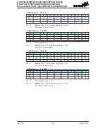
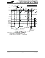
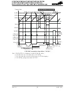
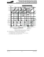
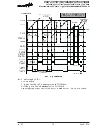
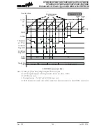
Capture Input Mode
To select this mode bits TnAM1, TnAM0 and TnBM1, TnBM0 in the TMnC1 and TMnC2 registers
should be set to 01 respectively. This mode enables external signals to capture and store the
present value of the internal counter and can therefore be used for applications such as pulse width
measurements. The external signal is supplied on the TPnA and TPnB_0, TPnB_1, TPnB_2 pins,
whose active edge can be either a rising edge, a falling edge or both rising and falling edges; the
active edge transition type is selected using the TnAIO1, TnAIO0 and TnBIO1, TnBIO0 bits in the
TMnC1 and TMnC2 registers. The counter is started when the TnON bit changes from low to high
which is initiated using the application program.
When the required edge transition appears on the TPnA and TPnB_0, TPnB_1, TPnB_2 pins the
present value in the counter will be latched into the CCRA and CCRB registers and a TM interrupt
generated. Irrespective of what events occur on the TPnA and TPnB_0, TPnB_1, TPnB_2 pins
the counter will continue to free run until the TnON bit changes from high to low. When a CCRP
compare match occurs the counter will reset back to zero; in this way the CCRP value can be used
to control the maximum counter value. When a CCRP compare match occurs from Comparator P,
a TM interrupt will also be generated. Counting the number of overflow interrupt signals from the
CCRP can be a useful method in measuring long pulse widths. The TnAIO1, TnAIO0 and TnBIO1,
TnBIO0 bits can select the active trigger edge on the TPnA and TPnB_0, TPnB_1, TPnB_2 pins
to be a rising edge, falling edge or both edge types. If the TnAIO1, TnAIO0 and TnBIO1, TnBIO0
bits are both set high, then no capture operation will take place irrespective of what happens on the
TPnA and TPnB_0, TPnB_1, TPnB_2 pins, however it must be noted that the counter will continue
to run.
As the TPnA and TPnB_0, TPnB_1, TPnB_2 pins are pin shared with other functions, care must
be taken if the TM is in the Capture Input Mode. This is because if the pin is setup as an output,
then any transitions on this pin may cause an input capture operation to be executed. The TnCCLR,
TnAOC, TnBOC, TnAPOL and TnBPOL bits are not used in this mode.


