
Document No: C-61-00003-3
S
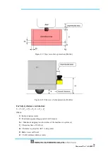
= Safety distance (mm)
K
= Approach speed 1600 (mm/s)
T
m
= Maximum stopping/run-down time of the machine or system (s)
T
s
= Response time of UAM (s)
C
= Additional distance of 850mm by considering arm intrusion (mm)
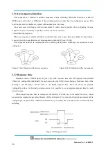
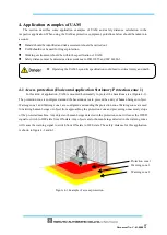
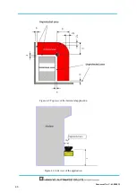
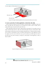
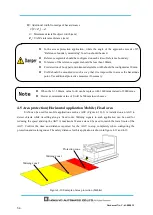
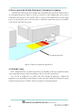
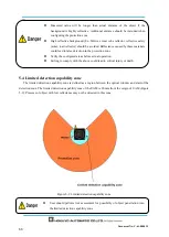
4.4 Access protection (Vertical application Stationary)
Figure 4-8 shows an example to prevent the access when part of the body is approached near the
hazardous area. If objects or part of body enters such area, OSSD signal switches to OFF state from ON-state.
UAM detects an object or human being in vertical plane in such configuration. It is not possible to detect an
object or human being at the front or back side of the detection plane. Therefore, caution should be taken
while deciding the distance between approaching point and hazardous area. The width of protection zone
should be sufficient to protect the hazardous area. Always use reference monitor function in such
applications to detect the displacement of fences and UAM which may expose the hazardous area. OSSD
signal will switch to OFF state when the position of reference is changed. The safety distance for this
application is shown in figure 4-8 and 4-9. Refer to section 7 for configuring the protection zone.
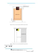
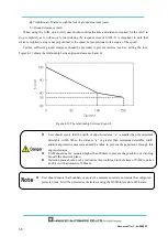
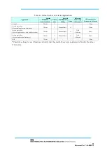
User should ensure that the width of unprotected
zone “a” is smaller than the
minimum detectable width. If the value of “a” is greater than minimum detectable
width, additional protective measures should be taken to prevent the penetration
through this unprotected zone.
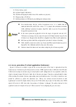
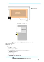
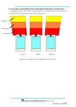
In the access protection application where the angle of approach exceeds ±30º,
“Reference monitoring” function should be used with 100mm tolerance range for the
reference zone. Response time should be configured below 90ms in such application.
Reference segments should be configured on each sides of reference boundary.
UAM should be mounted in such a way that accessibility towards hazardous point is
impossible. Use additional protective measures if necessary.
Tolerance should be taken in account when configuring the reference segments.
Содержание UAM-05LP
Страница 1: ... Document No C 61 00003 3 ...
Страница 104: ... Document No C 61 00003 3 Figure 7 33 b Function Figure7 33 c Area ...
Страница 107: ... Document No C 61 00003 3 Figure 7 36 a Project report tab Figure 7 36 b Error report tab ...
Страница 148: ... Document No C 61 00003 3 13 External dimension 13 1 UAM 05LP ...
Страница 149: ... Document No C 61 00003 3 13 2 Base mounting bracket ...
Страница 150: ... Document No C 61 00003 3 13 3 Rear mounting bracket ...
Страница 151: ... Document No C 61 00003 3 13 4 Cover Protection Bracket ...
Страница 152: ... Document No C 61 00003 3 14 EC Declaration of conformity ...
Страница 153: ... Document No C 61 00003 3 ...


