background image

 0055

 - 9

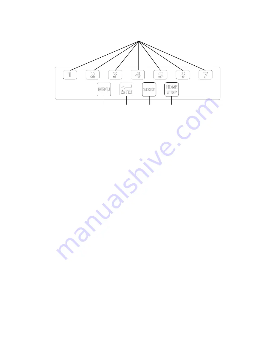
4.7 - KEYBOARD

Note:

Only press the keys with fingers; do not use counterweight pliers or other
pointed tools.

Fig. 7

Function keys: for immediate selection of functions shown on screen

Special functions

selection

Confirm

Measurement

cycle start

Machine cycle stop

Содержание Megaspin 800

Страница 1: ...erating instruction manual Protection cover Weight and accessories table Automatic width reading gauge Wheel balancer chuck Automatic distance diameter gauge Parking and emergency brake pedal Pneumatic chuck lock pedal Series A Series A Visual display unit Control panel Flange stakes HofmannIndustrialGmbH A 5302 Henndorf Hauptstraße 59 Tel 43 6214 6466 12 Fax 22 ...

Страница 2: ...3 2 RETRIEVINGSTOREDMEASUREMENTS 14 5 3 3 MANUALSETTING 15 5 4 USER MANAGEMENT 16 5 4 1 USER STORAGE 16 5 4 2 USER RETRIEVAL 16 5 5 5 4 MEASUREMENT RESULT 17 5 5 1 INDICATIONOFEXACTPOSITIONOFCORRECTIONWEIGHTS 18 5 5 2 SPLIT MANAGEMENT 19 5 5 3 IMBALANCEOPTIMISATION 20 5 5 4 ALU AND STATIC MODE 20 5 5 5 CORRECTINGSTATICIMBALANCE 21 5 6 STATISTICS 21 5 7 RUN OUTMEASUREMENT OPTIONAL 22 6 SETUP 23 6 1...

Страница 3: ...0055 3 ...

Страница 4: ...4 0055 Note Due to international agreements this machine may not be sold in the following countries France Germany Italy USA ...

Страница 5: ...wheel is correctly secured to the flange The machine operator must not wear loose clothing Unauthorised persons must not come near the wheel balancer during the operating cycle Avoid placing objects in the machine bed that could jeopardise correct wheel balancer operation 1 1 1 STANDARD SAFETY DEVICES STOP button for stopping the wheel in emergencies Highly resistant shockproof plastic protection ...

Страница 6: ... kg 6 seconds Balancing precision 1 gram Positionresolution 1 4 Meannoiselevel 70 dB A Rim machine distance 0 285 mm Settablerimwidth 1 5 20 or 40 510 mm Settablediameter 10 24 or 265 615 mm Total diameter of wheel within cover 1067 mm 42 Total width of wheel within cover 500mm Max wheelweight 65 kg Min max compressed air pressure 7 10 kg cm2 0 7 1 Mpa 7 10 BAR 100 145 PSI 2 HANDLING LIFTING NOTE ...

Страница 7: ... the releasemechanism 3 4 FURTHER SAFETY DEVICES MODEL P Wheel always locked even in the event of a pressure break during the balancing cycle Rotating block wheel clamping device to prevent the wheel coming off the flange in the event of the pneumatic clamping pedal being accidentally pressed during the balancing cycle Always operate the release control pedal when the machine is at a standstill th...

Страница 8: ...IC WHEEL POSITIONING At the end of the spin the wheel is positioned in line with the unbalance on the outer sidewall or on the static when selected Positioning is automatically disabled in the case of wheels below 13 in diameter Precision is 20 degrees for wheels weighing up to 25 kg 4 6 CLOCK MANAGEMENT The wheel balancer features a clock having an operating autonomy with the machine off of about...

Страница 9: ...ress the keys with fingers do not use counterweight pliers or other pointed tools Fig 7 Function keys for immediate selection of functions shown on screen Specialfunctions selection Confirm Measurement cycle start Machine cycle stop ...

Страница 10: ... If any key is touched or the wheel or distance diameter gauge are moved the screen will automatically switch back to the initial frame Automatic protection cover start is not possible from screen saver for safety reasons 5 1 2 SCREEN SAVER FRAME 5 WHEEL BALANCER INDICATIONS AND OPERATION The screen provides and shows various details as well as numerous operating options for the operator Such info...

Страница 11: ...ve weight dispenser Adhesive weight dispenser Run out measurement Run out measurement Run out measurement Run out measurement Run out measurement General customer details General customer details General customer details General customer details General customer details User names User names User names User names User names Settings Settings Settings Settings Settings SETTINGS SETTINGS SETTINGS SE...

Страница 12: ...els Usingthespecialgrip movetheendofthegaugeagainsttherim pushthegripperupwards and wait for the weight symbol on the screen to change from blue to red In the case of acoustic signal enabled see 6 8 dimension acquisition is indicated by a beep The calibration thus made is required for ALU 1 2 3 4 CTS Static and Dynamic modes Manual setting can be made using the buttons as described at 5 3 3 Press ...

Страница 13: ...is indicated by the colour of the correction weights which passes from blue to red Return the gauges to idle position N B If the symbols in fig 8C 8D remain on the screen this means that at least the relevant measurement gauge is not in idle position The two measurements distance diameter and width can be made at different times In this case first of all determine distance diameter The correct pos...

Страница 14: ...mensions ALU M wheel correction from inside for two balancing levels with direct calibration After measuring the inner sidewall FI as shown in fig 9 further remove the gauge to store the data of the outer sidewall FE Note Once the positions have been achieved always push the calipers upwards and hold these still for at least 2 seconds The counterweight symbols will change colour In the event of an...

Страница 15: ... pulling out the distance diameter gauge press to select the dimension to be set displayed in red press to set the desired value press to change the unit of measurement Definitionofdimensions DIAMETER Set the nominal diameter indicated on the rim WIDTH Set the nominal width shown on the rim DISTANCE With gauge idle determine the distance in cm of the machine wheel Set the value removing 1 5 cm Fig...

Страница 16: ...ill automatically return to the initial frame 5 4 2 USER RETRIEVAL Make a measurement spin with any dimensions Press the MENU button the MENU window will appear on the screen Press the window will display a list of available USERS The current USER is indicated in red Press the number indicating the desired USER The system will automatically return to the initial frame with recalculation of the unb...

Страница 17: ...h a precision of 0 5 g 0 1 oz The enabled buttons are Outstandingbalancedisplay Correction procedure selection DYNAMIC STATIC ALU1 ALU2 ALU3 ALU4 CTS By changing procedure the automatic recalculation occurs of the unbalance values in accordance with the previous spin 5 5 4 Run outmeasurementgraph optional Imbalance division management on settable components 5 5 2 Button only enabled with STATIC or...

Страница 18: ...tion of outstanding unbalance Press button on the measurement panel Remove the distance diameter gauge Movement of the weight towards the correction position is indicated by a coloured arrow that moves Once a fixed arrow has been reached turn the wheel to correction position FI or FE and fit the counterweight turning the clamp upwards until this attaches to the wheel In the event of the acoustic a...

Страница 19: ... along the vertical press themeasurementpanelwillreappearonthescreenwiththeunbalancefiguresalreadysplitup TheinnersidewallALU Munbalancedoesnotvary whilefortheoutersidewallSTATICandALU Munbalance two weights appear for the same sidewall slowly turn the wheel until an unbalance figure appears fitanadhesiveweightofthedisplayedvalue fortheoutersidewallorSTATIC behindthespokeuppermost along the vertic...

Страница 20: ...ingthemodeoptions Selectthetyperequiredbymeansofthenumericbuttons Returntomeasurementpanelwithrecalculatedfigures is automatic The upper section of the screen always shows a symbol indicating the enabled fitting position of theweights UNBALANCEOPTIMISATION IMPORTANT The previous spin must have been made with the currently fitted wheels Make a reference mark to indicate the rim flange position in o...

Страница 21: ... STATIC UNBALANCE Selectedfromset up thisoptimizestheoutstandingunbalance correctingawheelwithstandardcounterweights 5 grams at a time 1 4 ounces Thanks to this special function the position and best correction value is calculated so as to correct static unbalance which is the biggest cause of vibrations felt inside the vehicle 5 6 STATISTICS NUMBER OF DAILY SPINS this indicates the number of spin...

Страница 22: ...es for the two run outs After making a balancing spin the measurement of the tyre run out can be made automatically by means of the SONAR sensor on the cover The sensor must be manually positioned in front of the tread Fig A Fig B Epp E1h GRAPH1 represents the real Peak Peak run out GRAPH2 representsthefirstharmonicrun out Forawheelingoodcondition thisgraphshouldappear almost as a straight line By...

Страница 23: ...sfunctionisbestsetwhenthemachineisusedinstandardmodeasthebalancing quality is improved The computer performs a complex calculation whereby the static residue is cancelled by changing the value and position of the fixed value counterweights 5 grams at a time 1 4 ounces 6 5 SPIN WITH COVER CLOSED By selecting ON the automatic spin start is engaged when the cover is closed 6 6 SCREEN SAVER TIME When ...

Страница 24: ...machine can be customised by setting a The name to appear in the initial frame screen saver b The name of 4 different wheel balancer users USER NAME The screen will show an ideal keyboard with the set of characters available for writing messages The customer s name consists of 3 lines of at most 30 characters each User names have at most 15 characters each 7 3 RUN OUT MEASUREMENT ENGAGEMENT Engage...

Страница 25: ...facilitates troubleshooting At the end of the self diagnosis numerous parameters are indicated which are useful to the after sales service for finding machine faults HOME STOP Return to previous menu 7 4 4 1 ENCODER CONTROL In turning the chuck must change the angular position POS from 0 to 128 cause the UP message to appear by turning the wheel clockwise and the DOWN message to appear by turning ...

Страница 26: ...lf calibration Wheel unbalances too high 4 Motor turning in wrong direction 5 Protection cover open before start of spin 7 8 9 Machine setup parameter error Check basic setting parameters are correct and repeat wheel balancer calibration Contact after sales service 11 Speed too high for reading 12 13 14 Reading counter overflow Contact the after sales service 15 16 17 18 Contact the after sales se...

Страница 27: ...ECTION FUSES Accessible by removing the weight carrying table the power and power supply board features 4 protection fuses see exploded Tables Item 317 In the event of these having to be replaced fuses of identical current carrying capacity must be used If the fault reoccurs contact the after sales service THE OTHER MACHINE PARTS REQUIRE NO MAINTENANCE ...

Страница 28: ...r Erstellungsliste nummer Numéro de liste de construction Numero de fabricacion Fremstillingslistenummeret Tillverkningsnummer 900M800B2 6 905M800B2 6 with applicable regulations below mit folgenden einschlägigen Bestimmungen selon les normes ci dessous con directivas subaplicables i henhold til folgende direktiver med följande direktiv D P R Nr 459 from 24 July 1996 EC Directive EG Richtlinie Dir...

Отзывы: