- 23 -
5. Pull the tube with the white marking off of the front panel.
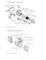
6. Lift out the inner frame (A5) and set it down, somewhat offset.
7.
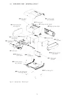
Pull off the bellows (A16) from blower box (A3) and flow element holder (E5) and dispose of the
cable tie.
8. Pull the motor cable (K10) through the opening of the inner frame and remove the blower box
from the inner frame.
9. Pull off the bellows (A7) from the blower box (A3) and dispose of the cable tie.
10.
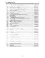
Take the new blower box and fit the bellows (A7) to the air inlet and fit the bellows (A16) to the
air outlet. Ensure that the bellows with the slots sit correctly in the blower box.
11. Insert the new blower box into the inner frame and, at the same time, feed the motor cable
(K10) through the opening in the inner frame. Ensure that the bellows (A7) with the slot sit cor-
rectly in the inner frame.
12. Pull the motor cable upwards in the slit at the back of the inner frame.
13.
Slip the angled air outlet bellows (A16) onto the flow element holder (E5).
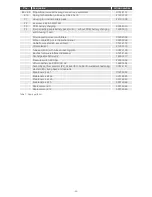
14. Fasten the bellows with the 142 mm cable tie (Maintenance kit 5). Cut off the cable tie’s pro-
truding end section with a side cutter.
15. Place the inner frame onto the upper part of the housing (A6). Ensure that the inner frame sits
exactly in the corresponding guides and no tubes get squeezed.
16.
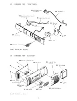
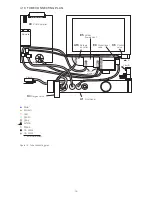
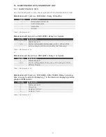
Take the front panel and plug the O2 connection tube (no color, +) onto the blower box accord
-
ing to the tube connecting plan (see Figure 12 on page 15). Fasten the O2 connection tube with
the 71 mm cable tie (Maintenance kit 5). Cut off the protruding end section with a side cutter.
17. Tie up the signal transmitter cable (K3), proportional valve cable (K6) and control valve cable
(K9) on the air outlet’s right-hand side with a cable tie (71 mm, Maintenance kit 5).
18. Place those three cables into the slender cable run on top of the air outlet unit. Then tie them
together with the humidifier cable (E6) on the left-hand side of the air outlet using a cable tie
(71 mm, Maintenance kit 5).
19.
Affix the whole cable harness together with the temperature sensor cable (K7) to the fixing
base at the top of the flow element holder using a cable tie (71 mm, Maintenance kit 5). Make
sure not to squeeze the temperature sensor cable (K7) by overtightening the cable tie.
20. Cut off the protruding cable tie end sections with a side cutter.
21. Press the ferrite core into the retaining clip on the inner frame.
22. Connect the O2 valve cable (K5) to the control valve cable (K9). Ensure the correct polarity.
23. Plug the tube with the white marking onto the control tube connection (white) on the inner side
of the front panel.
24. Take the PCB controller (A9) and reconnect all cables and tubes according to the cable and
tube connecting plans. While connecting the tubes, hold the pressure sensors tightly to avoid
damaging their pins.
25. The further assembly is described in section 6.10.
Содержание TRENDvent
Страница 1: ...Service Manual Ventilator TRENDvent ...

