16 (42)
3.4
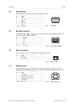
CAN Interface
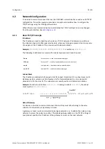
The CAN network connector is located on the bottom of the unit.
Fig. 9
CAN connector
Pin
Signal
2
CAN_L
3
CAN_GND
5
Shield
6
CAN_GND
7
CAN_H
1, 4, 8, 9
(reserved)
3.5
PROFINET Interface
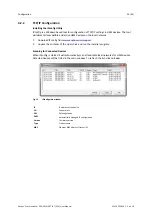
The PROFINET IRT interface contains a dual port Ethernet switch with RJ45 type connectors. The
two ports are labeled
LAN 1
and
LAN 2
.
1
8
Fig. 10
Ethernet connector (RJ45)
Pin
Function
1
TD+
2
TD-
3
RD+
6
RD-
4, 5, 7, 8
(reserved)
3.6
Power Connector
See also
regarding power supply requirements.
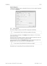
1 2
Fig. 11
Power connector
Pin
Signal
1
+24 VDC
2
Power Ground
3.7
USB Connector
The USB connector is used for connecting the Anybus Communicator CAN to a computer for
uploading and downloading configurations. The USB cable should be removed when not in use.
1
2
3
4
Fig. 12
USB type B connector
Pin
Signal
1
+5 V input
2
USBDM (USB communication)
3
USBDP (USB communication)
4
Signal ground
Housing
Cable shield
6
9
5
1 (male)
Anybus
®
Communicator
™
CAN PROFINET
®
IRT (2.32) User Manual
SCM-1202-035 1.2 en-US
Содержание Anybus Communicator CAN PROFINET IRT 2.32
Страница 40: ...This page intentionally left blank ...
Страница 43: ...This page intentionally left blank ...


