


© 2022 HME Clear-Com Ltd. All rights reserved.
2
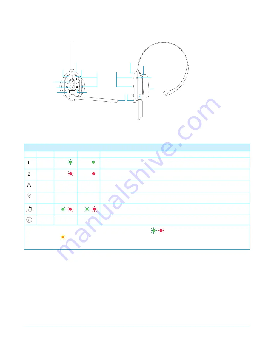
HEADSET OVERVIEW
Supports a Maximum of
40 All-in-one Headsets
Power Button
(blue)
BAT70 Battery
HEADSET
Front View
HEADSET
Side View
Earpad
Channel 1
Channel 2
Raised sections on
the bezel allow users
to identify keypad
buttons by touch.
Status
LED
Boom
LED
Status
LED
Volume Up
Volume Down
Action
Group Chat
Battery Release
Latch (silver)
Fig. 2
Keypad Layout Reference Table
Icon Label
Status LED Boom LED Status/Description
Chan 1
Green
Green
Tap to talk to channel 1. The Status LED flashes green while the Boom LED turns on
solid green. Tap again to stop. The Status LED turns solid; the Boom LED turns off.
Chan 2
Red
Red
Tap to talk to channel 2. The Status LED flashes red while the Boom LED turns on solid
red. Tap again to stop. The Status LED turns solid; the Boom LED turns off.
Volume
Up
Tap to increase volume (the headset beeps become louder as confirmation). Press and
hold to maximize volume to loudest.
Volume
Down
Tap to decrease volume (the headset beeps become quieter as confirmation). Press and
hold to minimize volume to quietest.
Group
Disconnects wired ports from talking and listening. Both Status and Boom LEDs flash
quickly, alternating red & green. Tap again to stop.
Action
No Function. Reserved for future functionality.
Notes
: Both the Status and Boom LEDs flash slowly with alternating colors
when the headset needs to be paired.
A yellow Status LED
indicates a low battery. The low battery Status LED is also accompanied by audio prompts.
Push-to-Talk mode:
Press and hold any audio button (1, 2 or Group Chat) to use in this mode (there is an audible single-tone
confirmation). Release to cease communication and exit this mode (there is an audible two-tone confirmation).
Table 2


