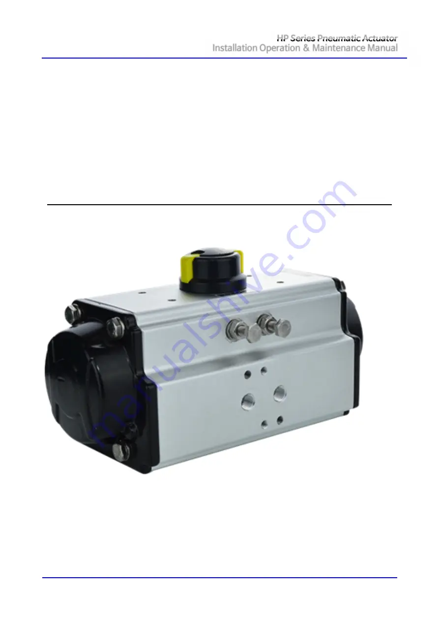
HP Series Pneumatic Actuator
Installation Operation & Maintenance Manual
Document No. HUMG-HP-16 Rev0
Page 1 / 18
Valve Automation Leader HKC
Installation, Operation & Maintenance Manual
Страница 1: ...Series Pneumatic Actuator Installation Operation Maintenance Manual Document No HUMG HP 16 Rev0 Page 1 18 Valve Automation Leader HKC HP Series Pneumatic Actuator Installation Operation Maintenance Manual ...
Страница 2: ...TS 5 1 9 TOOL INFORMATION 6 1 10 CONVEYANCE 6 1 11 SUPPLY AIR VOLUME 6 1 12 OPERATING TIME 7 1 13 WEIGHT 7 2 BILL OF MATERIALS 7 3 MOUNTING AND OPERATING 8 3 1 ACTUATOR MOUNTING 8 3 2 OPERATING PRESSURE AND METHOD 9 3 3 PRINCIPLES OF OPERATION 9 4 ASSEMBLY 10 4 1 ASSEMBLY OF ACCESSORIES VALVE 10 4 2 OPEN CLOSE ADJUSTMENT 12 4 3 HP SERIES SPRING SETS 13 5 DISASSEMBLY 14 5 1 ACTUATOR TESTING 15 6 TR...
Страница 3: ...the instructions contained within this Service Instruction are strictly adhered to and executed by well trained equipped prepared and competent personnel 1 1 6 When removing seals from seal grooves use a commercial seal removing tool or a small screwdriver with sharp corners rounded off 1 1 7 Use a non hardening thread sealant on all pipe threads 1 1 8 WARNING Apply the thread sealant per the manu...
Страница 4: ...ar max 1 4 Initial Inspection Upon on the receipt of the actuator the user should inspect the condition of the product and ensure that product specification stated in the name plate matches with the order sheet 1 4 1 Remove the packing wrap or wooden box carefully Inspect the product for any physical damage that may have occurred during shipment 1 4 2 Check the product specification with product o...
Страница 5: ...ion Tel 82 31 488 8266 Fax 82 31 488 8269 8696 Homepage www hkcon co kr Email hkcon hkcon co kr Address Sunggok dong 155 Byeolmang ro Danwon gu Ansan si Gyeonggi do Republic of Korea 15417 CAUTION n Turn off all power services before attempting to perform any service on the actuator n POTENTIAL HIGH PRESSURE VESSEL Before removing or disassembling your actuator ensure that the valve or other actua...
Страница 6: ...8 Impact end wrench set 4 Rubber or leather mallet 9 Impact socket 5 Air impact wrench Note Hexagons are metric standard tools 1 10 Conveyance 1 10 1 Ensure the actuator is fully vented and decontaminated before operation 1 10 2 Pay attention in shock 1 10 3 Ensure all power supplies are removed before operation 1 11 Supply air volume Model Part HP125 HP145 HP160 HP180 HP200 HP210 HP211 HP212 Inne...
Страница 7: ...5 HP160 HP180 HP200 HP210 HP211 HP212 Operating time sec DA SR DA SR DA SR DA SR DA SR DA SR DA SR DA SR Open 0 9 1 1 12 1 4 15 1 7 2 2 2 2 7 3 2 3 1 3 5 2 7 3 2 3 5 4 Close 1 2 1 4 1 5 1 8 1 8 2 1 2 4 2 8 3 5 4 4 4 5 4 3 4 3 5 5 5 1 13 Weight Model Part HP035 HP050 HP063 HP066 HP075 HP088 HP100 HP115 Type DA SR DA SR DA SR DA SR DA SR DA SR DA SR DA SR Close 0 54 1 16 1 28 1 68 1 82 2 4 2 6 3 3 4...
Страница 8: ... 20 1 Drive Shaft Steel alloy 21 1 Bearing Pinion bottom Nylon 46 22 1 O Ring Pinion bottom Nitrile NBR70 NBR FKM VMQ 23 1 O Ring Stop screw Nitrile NBR70 NBR FKM VMQ 24 2 Stop Bolt Washer Stainless Steel 25 2 Stop Nut Stainless Steel 26 2 Stop Bolt Stainless Steel 27 5 12 Spring Cartridge High alloy Spring Steel Epoxy coated 28 1 Spring Holder Polypropylene GF 3 Mounting and Operating 3 1 Actuato...
Страница 9: ... maximum operating Air supply pressure should not exceed 8 bar 115psi The air supply should be clean dry and lubricated 3 2 2 CAUTION Before using an alternative air supply that is not of instrument quality please consult with HKC Co Ltd 3 3 Principles of Operation 3 3 1 Air connections double acting OPEN Air to port 2 counter clockwise open CLOSE Air to port 4 clockwise close Pistons must be inve...
Страница 10: ...sories valve 4 1 1 Assembly of valve Direct mounting Spring to Open Air to port 2 clockwise close Spring return counter clockwise open Valve close Actuator close Caution Never disassemble a valve that is under pressure FIG 1 Make sure that both valve and actuator are close FIG 2 Insert actuator on top of adapter and assembly it through screws ...
Страница 11: ...ng torque table Nm M5 5 6 M6 10 11 M8 23 25 M10 48 52 M12 82 86 M14 132 138 M16 200 210 M20 390 410 M24 675 705 M30 1340 1400 Solenoid valve Before mounting a s o valve ensure that the actuator is in its normal position close Valve position monitor or Positioner Fit the valve position monitor or positioner and bracket on the actuator using four screws provided Bracket Pneumatic Actuator Solenoid v...
Страница 12: ...the square of the actuator and bolt together through the valve ISO pad max tightening torque see table above 4 2 Open close adjustment OPEN CLOSE Adjustment of HP 050 212 series Except with HP 035 OPEN CLOSE Adjustment of END STOPPER TYPE Option or HP 035 4 2 1 Adjustment CLOSE After Valve and Actuator are assembled for Close condition adjust stop bolt inside actuator for correct closed condition ...
Страница 13: ...left hand Adjust and fix STOP BOLT using hex wrench Clockwise OPEN Counterclockwise OPEN Tighten and fasten NUT while STOP BOLT is being fixed by hex wrench 4 3 HP Series Spring Sets ASSEMBLY SET 5 SET 6 SET 7 SET 8 SET 9 SET 10 SET 11 SET 12 Caution If the actuator is a spring return model uniformly loosen all end caps screws two to three turns at a time in sequence to relieve pre load of the spr...
Страница 14: ...aft assembly 5 4 Pistons disassembly Holding the body in vice rotate the drive shaft until the piston 5 9 Pistons assembly 5 8 Pistons assembly 5 7 Pistons shaft assembly 5 2 Remove both open close stop cap screws together with nut and washer and o ring 5 3 Remove end cap screws 5 1 Remove cap screws 5 12 Indicator assembly 5 11 End cap assembly 5 10 Spring assembly ...
Страница 15: ...ndition 5 1 3 Check the piston for leaks 5 1 4 The cover drive shaft and air ports should be tested by pressurizing each port in turn and applying the test procedure 5 1 5 Remove pressure from the pressure inlet port 5 1 6 If an actuator was disassembled and repaired the above leakage test must be performed again 6 Trouble Shooting Guide Table 6 1 provides solutions for the most commonly encounter...
Страница 16: ... 49 5 136 116 30 80 PF M6 1 8 20 4 4 12 24 16 32 HP100 268 123 67 56 148 128 30 80 PF M6 1 4 20 4 4 12 24 16 32 HP115 316 141 77 64 166 146 30 80 PF M6 1 4 20 4 4 12 24 16 32 HP125 347 151 82 69 179 159 30 80 PF M6 1 4 20 4 4 12 24 16 32 HP145 414 172 92 80 209 179 30 80 PF M6 1 4 30 4 4 12 24 16 32 HP160 467 190 101 89 226 196 30 130 PF M6 1 4 30 4 4 12 24 16 32 HP180 497 206 107 99 251 221 30 13...
Страница 17: ...l Flange L ISO5211 Q Base Tap DP mm R Stem mm M DP N HP035 F03 F05 M5 M6 10 9 Ø36 Ø50 9 10 HP050 F03 F05 M5 M6 12 11 Ø36 Ø50 9 10 HP063 F05 F07 M6 M8 17 14 Ø50 Ø70 11 14 HP066 F05 F07 M6 M8 17 14 Ø50 Ø70 11 14 HP075 F05 F07 M6 M8 19 17 Ø50 Ø70 12 14 HP088 F05 F07 F10 M6 M8 M10 22 17 Ø50 Ø70 Ø102 12 14 18 HP100 F07 F10 M8 M10 22 17 Ø70 Ø102 14 18 HP115 F07 F10 M8 M10 25 22 Ø70 Ø102 Ø70 Ø102 14 18 H...
Страница 18: ...HP Series Pneumatic Actuator Installation Operation Maintenance Manual Document No HUMG HP 16 Rev0 Page 18 18 ...