Installation and Maintenance Manual
HKC
HM-SERIES / ACTUATORS
Version- V1
Document No. HQOI-08-EV1
DATE : 2011.12.22
H K C
WWW.HKCON.CO.KR
HKC CO.,LTD.
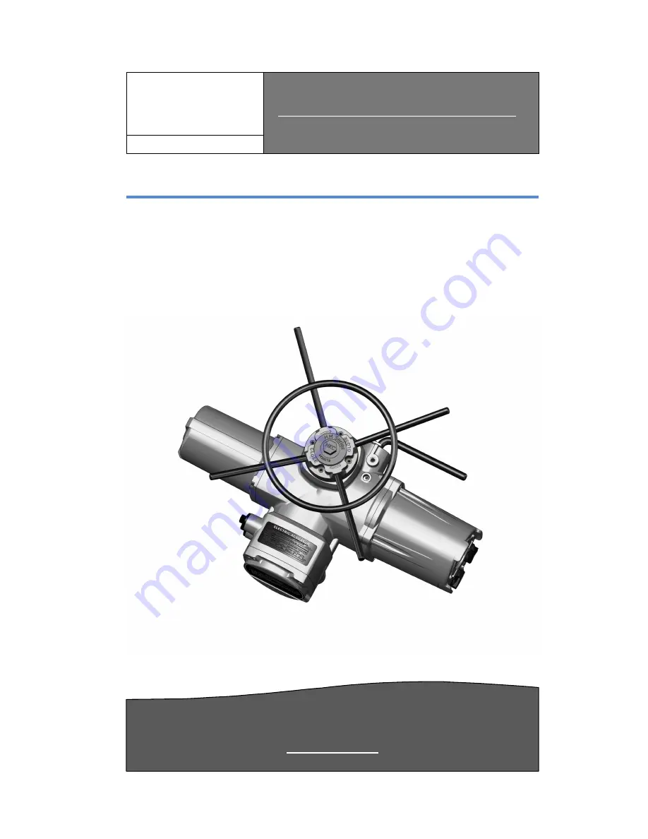
HM – Series. ELECTRIC ACTUATORS
INTELLIGENT MULTI-TURN ELECTRIC ACTUATORS
VALVE AUTOMATON
Страница 1: ...nd Maintenance Manual HKC HM SERIES ACTUATORS Version V1 Document No HQOI 08 EV1 DATE 2011 12 22 H K C WWW HKCON CO KR HKC CO LTD HM Series ELECTRIC ACTUATORS INTELLIGENT MULTI TURN ELECTRIC ACTUATORS VALVE AUTOMATON ...
Страница 2: ...Data Standard 10 3 4 HM Option Technical Data Optional 11 3 5 Duty Cycle 11 3 6 Hand wheel and Declutching 11 3 7 Lubrication 12 3 8 Internal Parts for Standard Models 13 4 Installation and operation instruction 4 1 Pre installation for use in general service 14 potentially explosive atmosphere 4 2 Actuator Mounting 14 4 3 Actuator Mounting Details ISO5211 5210 15 4 3 1 Mounting base 15 4 3 2 Disa...
Страница 3: ...rocedures When setting up the actuator utilize the remote control to set the torque etc as they are individually displayed on screen This feature may reduce the risk of danger as setup can be remotely carried out at a safer distance The help menus for the control system of the valve and Actuator are ava screen hence user friendly Configuration alarm and status tests are given in English default Mo...
Страница 4: ...l safety Alerts the user to danger or harm The hazard or unsafe practice will result in severe injury or death WARNING Refers to personal safety Alerts the user to potential danger Failure to follow warning notices could result in personal injury or death CAUTION Directs the user s attention to general precautions that if not followed could result in personal injury and or equipment damage Externa...
Страница 5: ...o operate between the given ranges on the nameplate of each actuator In the case where products are exposed to temperature ranges that exceed the allowed range do not check for damage as it could result in severe injury Consult with the manufacturer as soon as possible Do not attempt to alter the Actuator physically as this could lead to leakage and malfunction of the product Before performing mai...
Страница 6: ... safety Actuator manual operation Read the manual operation section carefully and follow as directed In remote mode the Actuator can be controlled to be switched on and off Identification Product Identification actuator name plate is located on the side of the opposite of the conduit entry The name plate contains the following information Marking trade mark Base Size Torque Max Motor supply Motor ...
Страница 7: ...sed in water or buried in snow If the Actuator cannot be placed immediately make sure to store it in a dry area It is recommended that if the Actuator cables cannot be installed immediately use the plastic plug with PTFE tape to block seal where the metal plugs are located When sealed correctly the internal electronics are preserved from external corrosion for extended periods of time up to 1 year...
Страница 8: ...540 850 1300 1700 48 57 35 68 200 250 470 680 1000 1360 72 86 35 48 176 250 470 680 1000 1360 96 115 35 40 142 230 370 540 750 1000 144 173 105 150 260 400 650 860 192 230 540 730 3 2 2 AC 1Phase Model Torque Nm RPM MODEL TORQUE Nm 1Phase AC110 220V HM040 은 220V 이상 50HZ 60HZ HM04 HM08 HM11 HM20 HM40 HM 60 HM100 HM150 HM200 HM300 18 21 65 165 450 24 29 60 130 400 36 43 45 130 350 48 57 40 125 320 7...
Страница 9: ...6 30 100 96 115 25 80 3 2 4 Mechanical Data Mechanical Data MODEL HM04 HM08 HM11 HM20 HM40 HM60 HM100 HM150 HM200 HM300 Flange size ISO5211 F10 F10 F10 F14 F14 F16 F25 F30 F25 F30 Weight 30 30 30 65 65 70 190 190 200 200 Thrust rating Nm 44 44 44 100 100 150 220 220 334 445 Stem acceptance diameter maximum size BASE unit mm Thrust Rising 32 32 32 38 38 54 64 70 70 83 Non rising 26 26 26 32 32 45 5...
Страница 10: ...4 300 3ph 14 3000Nm direct drive When combined with gear box up to 43000Nm or 500 000Nm quarter turn available HM08 20 40 1ph 25Nm 450Nm HMS04 40 25Nm 450Nm Motor induction motor Monitoring Switches 4 Switches 250 VAC 16A rating option 8 Switches 16 Switches Travel Angle 0 10 000 000 turn Indicator Digital Display position indicator Signal lamp unit red open green close yellow fault Manual Overrid...
Страница 11: ...g HMS1 or HMS3 04 40 1200starts hour S4 50 duty cycle based on a modulation torque of 50 of rated torque Note 1 Type of duty according to VDE 0530 IEC 60034 1 3 6 Hand wheel and Declutching HM actuators provide a declutch able manual override system In order to manually operate the actuator Push the manual override engagement lever towards the hand wheel until it remains in position Turn the hand ...
Страница 12: ... H HK KC C 12 Note The override engagement lever returns automatically to auto position when the actuator is operated electrically 3 7 Lubrication HM is a totally enclosed unit with a permanently lubricated gear train Moly EP Grease Once installed lubrication should not be required However periodic preventative maintenance will extend the operating life of the actuator ...
Страница 13: ... Op pe er ra at ti io on n M Ma an nu ua al l H HK KC C 13 Torque Sensor Assembly Weatherproof Terminal 47P Main Control Board Control Board Supporter Power Board LCD Display Local Control Motor Drive Assembly Gear Assembly Declutching Manual Handle Override Assembly Reversing Contactor 3 8 Internal Parts for Standard Models ...
Страница 14: ...te 1 Further information should be use of the HM electric actuator catalogue Warning Read this installation and maintenance manual carefully and completely before attempting to install operate or troubleshoot any HKC actuator 4 2 Actuator Mounting Note Prior to mounting the actuator must be checked for any damage Damaged parts must be replaced by original spare parts Mounting is most easily carrie...
Страница 15: ...all incoming power Do not attach ropes or hooks to the hand wheel for the purpose of lifting by hoist 4 3 Actuator Mounting Details ISO5211 5210 4 3 1 Mounting base Table Torque and thrust values ISO5210 Flange Torque Thrust PCD A B Number of Type N m Kn mm Bolt F10 100 40 102 M10 4 F12 250 70 125 M12 4 F14 400 100 140 M16 4 F16 700 150 165 M20 4 F25 1 200 200 254 M16 8 F30 2 500 325 298 M20 8 Not...
Страница 16: ...ti io on n M Ma an nu ua al l H HK KC C 16 Mounting Base disassembly 4 3 2 Disassembly of Mounting Base Follow the steps as illustrated with hexagonal wrench to disassemble the base from Actuator The HM Series has one lower Base therefore it the easiest way to start disassembly of the Mounting Base Order of Disassembly Thrust Base assembly ...
Страница 17: ...make sure it is not damaged This applies similarly to the O Ring located on the upper part of the Drive Bush When working on the Drive Bush make sure all measurements and calculations for the valve stem is correct Make sure the protective bearing s O Ring is not damaged Assembly 1 Remove foreign particles on the Drive Bushing Once clean do the same for the Stop Ring and other O Rings Make sure the...
Страница 18: ...tructed personnel under the control and supervision of such an electrician and in accordance with the applicable electrical engineering rules For cable gland or conduit entries that are not used user or installer shall close by certified blanking elements so that the flameproof properties of the enclosure are maintained Flameproof enclosure Treat cover with care Gap surfaces must not be damaged in...
Страница 19: ...he motor rotates in the right direction Standard units are counter clockwise to open set Test the actuator and check the limit switches work correctly Check that all cable glands are correctly tighten Applicable cable glands should be selected to meet the application conditions In potentially explosive environments cable gland grades exceeding IP67 are recommended When fitting the cover verify tha...
Страница 20: ...iness of internal electrical devices Insure conduit connections are installed properly and are dry Check internal devices for condensation Check enclosure O ring seals and verify that the O rings are not pinched between flanges Verify declutch mechanism Visually inspect during open close cycle Inspect identification labels for ware and replace if necessary Warning Flameproof enclosure Before openi...
Страница 21: ...actuator wiring diagram Check limit switch cams Actuator is receiving power but does not operate Verify the line voltage to the actuator Check actuator torque to see if it s greater than the valve torque Check limit switches and cams Check that the torque switches have not tripped Check mechanical travel stop adjustment Verify the actuator against valve rotation standard units are anti clockwise o...
Страница 22: ...nd sealing Check whether Ex connections are fastened correctly Take care of possible discolouration of the terminals and wires Check the flame path gaps of flameproof enclosures for dirt and corrosion Since the dimensions of all Ex gaps are strictly defined and inspected no mechanical work shall be performed on them Ensure that all housing covers are handled carefully and that the seals are checke...
Страница 23: ...r I In ns st ta al ll la at ti io on n a an nd d O Op pe er ra at ti io on n M Ma an nu ua al l H HK KC C 23 8 Wiring Diagram 8 1 HM Standard 3ph Danger HAZARDOUS VOLTAGE No electrical power should be connected until all wiring and limit switch adjustments have been completed ...
Страница 24: ...to or r I In ns st ta al ll la at ti io on n a an nd d O Op pe er ra at ti io on n M Ma an nu ua al l H HK KC C 24 8 2 HM Standard 3ph CPT Danger HAZARDOUS VOLTAGE No electrical power should be connected until all wiring and limit switch adjustments have been completed ...
Страница 25: ...to or r I In ns st ta al ll la at ti io on n a an nd d O Op pe er ra at ti io on n M Ma an nu ua al l H HK KC C 25 8 3 HM Standard 3ph PCU Danger HAZARDOUS VOLTAGE No electrical power should be connected until all wiring and limit switch adjustments have been completed ...
Страница 26: ...H HM M S Se er ri ie es s E El le ec ct tr ri ic c A Ac ct tu ua at to or r I In ns st ta al ll la at ti io on n a an nd d O Op pe er ra at ti io on n M Ma an nu ua al l H HK KC C 26 8 Dimension ...
Страница 27: ...er ri ie es s E El le ec ct tr ri ic c A Ac ct tu ua at to or r I In ns st ta al ll la at ti io on n a an nd d O Op pe er ra at ti io on n M Ma an nu ua al l H HK KC C 27 9 Grounding EXTERNAL GROUND INTERNAL GROUND ...
Страница 28: ... s E El le ec ct tr ri ic c A Ac ct tu ua at to or r I In ns st ta al ll la at ti io on n a an nd d O Op pe er ra at ti io on n M Ma an nu ua al l H HK KC C 28 A AP PP PE EN ND DI IX X Ⅰ Ⅰ Ⅰ Ⅰ Ⅰ Ⅰ Ⅰ Ⅰ HM series Coding System ...
Страница 29: ...HM 200 300 HM 300 B ENCLOSURE 1 Weather proof IP67 2 Watertight IP68 3 EX type C MOTOR VOLTAGE 1 110V AC 1PH Only HM 008 020 2 220V AC 1PH Only HM 040 3 220V AC 3PH 4 380V AC 3PH 5 440V AC 3PH 6 460V AC 3PH 7 480 600V AC 3PH D RPM 1 18 21 50Hz 60Hz 2 24 29 3 36 43 4 48 57 5 72 86 6 96 115 7 114 173 1 8 192 230 1 E OPTION 1 0 N A 1 PCU Proportional Control Unit Input Output 0 10VDC 4 20mA DC 2 AMS1...