


53
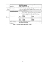
3.4.8 Encoder Signal Input and Connection
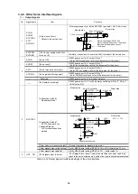
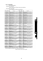
The following table shows the requirements for the encoder signal input circuits.
No.
Signal name
Item
Contents
1
Encoder signal
AP, AN
BP, BN
ZP, ZN
GND
[Input circuit form]
Photocoupler input
[For differential encoder output]
A/B-phase: SW1-1, 2 OFF
Z-phase: SW1-3 OFF
The GND levels must match between module and driver sides.
[Input circuit form]
Photocoupler input
[For open-collector
encoder output]
A/B-phase: SW1-1, 2 (ON)
Z-phase: SW1-3 (ON)
The GND levels must match between module and driver sides.
[Multiplication setting]
Set by G9003 initial setting (RENV2-b10, b9)
(Initial value: x4)
[Phase advancement/delay
setting]
Set by G9003 initial setting (RENV2-b11)
(Initial value: CW direction plus)
[Z-phase input signal polarity
switching]
Set by G9003 initial setting (RENV2-b12)
(Initial value: + pulse)
Table 3.4-11 Encoder signal input circuits
+5V
AP (BP, ZP)
AN (BN, ZN)
GND
GND
4.7K
150
220
+5V
AP(BP, ZP)
AN(BN, ZN)
GND
GND
4.7K
150
220
TLP115A or equivalent
TLP115A or equivalent
Module side
Encoder side
Encoder side
Module side
SW1: encoder type setting
A-phase: SW1-1 (OFF)
B-phase: SW1-2 (OFF)
Z-phase: SW1-3 (OFF)
SW1: encoder type setting
A-phase: SW1-1 (ON)
B-phase: SW1-2 (ON)
Z-phase: SW1-3 (ON)
Содержание motionCAT HCPCI-MNT720M
Страница 1: ...Motion Network System motionCAT series User s Manual Introduction Hivertec inc http www hivertec co jp...
Страница 3: ......
Страница 12: ...1 Warnings and Precautions...
Страница 20: ...9 1 motionCAT Installation...
Страница 109: ...98 4 Installation Guide...
Страница 118: ...107 5 Device Driver Installation...
Страница 122: ...111 6 Trial Operation...
Страница 145: ...134 7 Accessories...
Страница 147: ...136 8 Glossary...
Страница 161: ...150 9 Connections to Drivers Supplied by Manufacturers...


