


43
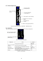
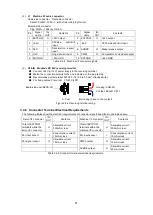
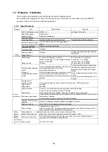
3.2.3 Indicators
The communication module is provided with LEDs that indicate the communication and power supply
status.
Figure 3.2-2 Indicator LED positions
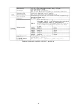
Display item
Status
Indicator
When communication
module is followed by
P, W, or C module
Except the left
configuration
During cyclic communication
Green ON (Red OFF)
Cyclic communication
indicator
(Red/Green)
While cyclic communication is stopped
Red ON
(Green OFF)
OFF
At disconnection of communication cable
or communication error during cyclic
communication
Red ON (Green OFF)
POW ON indicator
While voltage is applied to the receiving
terminal
Green ON
(Green)
While power supply is not connected to
the receiving terminal or current is cut off
by poly switch
OFF
Table 3.2-2 LED indicators
F
12
B
A
CDE
6 57
8
9
0
34
F
12
B
A
CDE
6 57
8
9
0
34
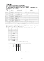
Cyclic communication indicator
(Top: Red, Bottom: Green)
Communication module POW
ON indicator (Green)
Содержание motionCAT HCPCI-MNT720M
Страница 1: ...Motion Network System motionCAT series User s Manual Introduction Hivertec inc http www hivertec co jp...
Страница 3: ......
Страница 12: ...1 Warnings and Precautions...
Страница 20: ...9 1 motionCAT Installation...
Страница 109: ...98 4 Installation Guide...
Страница 118: ...107 5 Device Driver Installation...
Страница 122: ...111 6 Trial Operation...
Страница 145: ...134 7 Accessories...
Страница 147: ...136 8 Glossary...
Страница 161: ...150 9 Connections to Drivers Supplied by Manufacturers...


