background image


Hitachi Virtual Storage Platform

G600

Hardware Reference Guide

MK-94HM8022-05

June 2016

G400,

Содержание Virtual Storage Platform G400

Страница 1: ...Hitachi Virtual Storage Platform G600 Hardware Reference Guide MK 94HM8022 05 June 2016 G400 ...

Страница 2: ...orized employees and other individuals to access relevant data and 2 Verifying that data continues to be held retrieved deleted or otherwise processed in accordance with relevant laws Notice on Export Controls The technical data and technology inherent in this Document may be subject to U S export control laws including the U S Export Administration Act and its associated regulations and may be su...

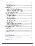
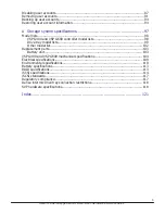
Страница 3: ...ges in this revision 13 Document conventions 13 Conventions for storage capacity values 14 Accessing product documentation 15 Getting help 15 Comments 15 1 Product overview 17 Block configuration 19 File and block level configuration 19 Hitachi Virtual Storage Platform G400 model 19 Hitachi Virtual Storage Platform G600 model 20 Features 22 Scalability 22 Examples of supported Hitachi Virtual Stor...

Страница 4: ...el 38 LFF front panel without bezel 38 LFF rear panel 39 Flash module drive FMD tray 40 FMD with front panel bezel 40 FMD front panel without bezel 41 FMD rear panel 42 Dense intermix drive tray 43 Dense intermix drive tray with front panel bezel 43 Dense intermix drive tray display LEDs 44 Dense intermix drive tray rear panel 45 SFF and LFF AC power supply unit LEDs and connectors 46 Hitachi Virt...

Страница 5: ...el list 102 Replacement parts 103 Battery unit 103 VSP G400 and VSP G600 mechanical specifications 104 Electrical specifications 109 Environmental specifications 110 Battery specifications 113 RAID specifications 113 iSCSI specifications 114 iSCSI standards 117 Regulatory compliance 117 Dense intermix drive tray connection restrictions 118 SVP hardware specifications 118 Index 121 5 Hitachi Virtua...

Страница 6: ...6 Hitachi Virtual Storage Platform G400 G600 Hardware Reference Guide ...

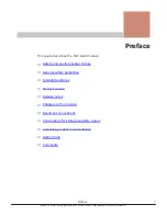
Страница 7: ...ral safety guidelines Intended audience Product version Release notes Changes in this revision Document conventions Conventions for storage capacity values Accessing product documentation Getting help Comments Preface 7 Hitachi Virtual Storage Platform G400 G600 Hardware Reference Guide ...
Страница 8: ... its packaging means that your electrical and electronic equipment should be disposed at the end of life separately from your household wastes There are separate collection systems for recycling in the European Union For more information contact the local authority or the dealer where you purchased the product Recycling A nickel metal hydride battery is used in the Cache Backup Battery A nickel me...

Страница 9: ...ur operation The array complies with FDA radiation performance standard 21 CFR subchapter J EMI regulation This equipment has been tested and found to comply with the limits for a Class A digital device pursuant to Part 15 of the FCC Rules These limits are designed to provide reasonable protection against harmful interference when the equipment is operated in a commercial environment This equipmen...

Страница 10: ...a caution in this manual use a proper lifting tool or have somebody assist you Preventing electric shock Before starting work be sure that unless otherwise specifically instructed there is no potential electric hazard in the maintenance area such as insufficient grounding or a wet floor Before starting work know where the emergency power off switches are located and be sure you know how to operate...

Страница 11: ...recautions when using the storage system Use the supplied power cords included with the storage system Do not use the supplied power cords for other products Do not use other power cords with the storage system Shut off the power feed to the equipment and inform the system administrator immediately if you notice an unusual smell abnormal heat generation or smoke emission Leaving such conditions un...

Страница 12: ... device after powering off the storage system and retain the key Attach a notice on the panel or board prohibiting the use of the switch If the machine power has been already turned off confirm that these conditions have been satisfied For fire Shut off all the power to the machine Turn off the emergency power switch or stop the power supply to the storage system If the fire continues to burn afte...

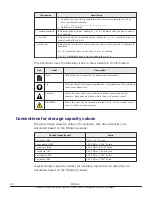
Страница 13: ...now supported Added support for a virtual service processor Made editorial changes to content Document conventions This document uses the following typographic conventions Convention Description Bold Indicates text in a window including window titles menus menu options buttons fields and labels Example Click OK Indicates emphasized words in list items Italic Indicates a document title or emphasize...

Страница 14: ...ip Provides helpful information guidelines or suggestions for performing tasks more effectively Caution Warns the user of adverse conditions and or consequences for example disruptive operations data loss or a system crash WARNING Warns the user of a hazardous situation which if not avoided could result in death or serious injury Conventions for storage capacity values Physical storage capacity va...

Страница 15: ...ucts and solutions sold by Hitachi Data Systems To contact technical support log on to Hitachi Data Systems Support Connect for contact information https support hds com en_us contact us html Hitachi Data Systems Community is a global online community for HDS customers partners independent software vendors employees and prospects It is the destination to get answers discover insights and make conn...

Страница 16: ...16 Preface Hitachi Virtual Storage Platform G400 G600 Hardware Reference Guide ...
Страница 17: ... and block access using iSCSI protocols in addition to the block access provided directly by iSCSI and FC I O modules All storage system models allow defective drives to be replaced without interruption of data availability to host computers A hot spare drive can be configured to replace a failed drive automatically securing the fault tolerant integrity of the logical drive Self contained hardware...

Страница 18: ... Features Scalability 18 Product overview Hitachi Virtual Storage Platform G400 G600 Hardware Reference Guide ...

Страница 19: ...losure that includes two controllers two optional NAS modules to support file operations but no disk drives Drives are supported using drive trays connected to the controllers The storage system supports 128 GB of high speed memory cache arranged as 64 GB per controller Storage system interfaces consist of 8 GB Fibre Channel 56 ports per system or 64 ports per systems for systems with no drives 16...

Страница 20: ... BNST DW F800 DB60C 3 5 inch LFF 60 4U 174 3 mm Related references Examples of supported Hitachi Virtual Storage Platform G400 configurations on page 22 Hitachi Virtual Storage Platform G600 model The storage system consists of a 4U enclosure that includes two controllers two optional NAS modules to support file operations but no disk drives Drives are supported using drive trays connected to the ...

Страница 21: ...me Supported drive types Number of drives supported Height SFF drive tray DW F800 DBS power supply contains BNST DW F800 DBSC 2 5 inch SFF 24 2U 86 2 mm LFF drive tray DW F800 DBL power supply contains BNST DW F800 DBLC 3 5 inch LFF 12 2U 86 2 mm FMD drive tray DW F800 DBF Flash module drive FMD 12 2U 86 2 mm FMD drive tray DW F800 DBF Flash module drive FMD 16 1 spare 2U 86 2 mm Dense intermix dr...

Страница 22: ... All storage systems offer pay as you grow scalability by allowing you to hot add drives as you need them Examples of supported Hitachi Virtual Storage Platform G400 configurations Related references Hitachi Virtual Storage Platform G400 model on page 19 Examples of supported Hitachi Virtual Storage Platform G600 configurations Drive tray Maximum number of drive trays supported Maximum number of d...

Страница 23: ...HDDs or SSDs VSP G600 Controller Maximum drive trays Maximum number of drives Drive trays Maximum number CBLM SFF 24 576 HDDs or SSDs CBLM LFF 24 288 HDDs or SSDs CBLM FMD 24 288 FMDs HAF 4 48 FMDs CBLM Dense intermix drive tray 12 720 HDDs or SSDs Number of mounted drive trays for VSP G400 up to 12 per path Maximum number of mounted drives for VSP G400 SFF LFF drives Dense intermix drive tray SFF...

Страница 24: ...ays for VSP G600 up to 6 per path Maximum number of mounted drives for VSP G600 SFF LFF drives Dense intermix drive tray SFF drive dense intermix drive tray LFF drive dense intermix drive tray 24 0 576 288 21 1 564 312 20 2 600 360 17 3 588 384 16 4 624 432 13 5 612 456 12 6 648 504 9 7 636 528 8 8 672 576 5 9 660 600 4 10 696 648 1 11 684 672 0 12 720 720 The maximum number of drive trays that ca...

Страница 25: ...describe the storage system hardware Storage system controllers Controller interfaces Storage system drive trays Hitachi Virtual Storage Platform SVP server Hardware description 25 Hitachi Virtual Storage Platform G400 G600 Hardware Reference Guide ...
Страница 26: ...ption 1 POWER LED Green Storage system is powered on Amber Storage system is receiving power 2 READY LED Green Normal operation 3 WARNING LED Off Normal operation Amber Component requires maintenance Blink Failure requires maintenance When System Option Mode 1097 is set to ON the WARNING LED does not blink even if the following failure information SIM issues failure information SIM 452xxx 462xxx 3...

Страница 27: ... key Note Removing a controller can cause the POWER READY WARNING and ALARM LEDs on the front panel to activate These LEDs return to the on status after the storage system recovers from the controller replacement CBLM front panel without bezel Number Item Description 1 POWER ON OFF main switch Powers the storage system 2 POWER READY WARNING ALARM LEDs See the previous table 3 Controllers Controlle...

Страница 28: ...nly when instructed by Hitachi Support 10 STATUS LED for BKMF Green Charging of the battery in the backup module is complete Red Backup module can be removed Blink red one time Main battery failure Blink red two times Backup battery failure Blink red three times Both batteries failed or preventive maintenance replacement of batteries can be performed Off Battery is not mounted battery mounting fai...

Страница 29: ...umber Item 1 Power supply unit 2 Front end module 3 Back end module 4 LAN blade Rear view includes NAS modules Hardware description 29 Hitachi Virtual Storage Platform G400 G600 Hardware Reference Guide ...
Страница 30: ...ow the status of the storage system Front end module descriptions 8 Gbps Fibre Channel board LEDs and connectors Number Item Description 1 Fibre Channel connectors Connect to Fibre Channel cables 2 STATUS LED Green front end module is in power on state Red front end module can be removed safely 3 PORT LED Red Small form factor pluggable can be removed 30 Hardware description Hitachi Virtual Storag...

Страница 31: ...B 1B 3B 5B 7B CHB 1C 1C 3C 5C 7C CHB 1D 1D 3D 5D 7D CHB 1E 1E 3E 5E 7E CHB 1F 1F 3F 5F 7F CHB 1G 1G 3G 5G 7G CHB 1H 1H 3H 5H 7H CHB 2A 2A 4A 6A 8A CHB 2B 2B 4B 6B 8B CHB 2C 2C 4C 6C 8C CHB 2D 2D 4D 6D 8D CHB 2E 2E 4E 6E 8E CHB 2F 2F 4F 6F 8F CHB 2G 2G 4G 6G 8G CHB 2H 2H 4H 6H 8H 16 Gbps Fibre Channel board LEDs and connectors Hardware description 31 Hitachi Virtual Storage Platform G400 G600 Hardw...

Страница 32: ...annel connectors Connect to Fibre Channel cables Port Assignments CHB 16 Gbps Fibre Channel Ports left to right Port 1 Port 2 CHB 1A 1A 3A CHB 1B 1B 3B CHB 1C 1C 3C CHB 1D 1D 3D CHB 1E 1E 3E CHB 1F 1F 3F CHB 1G 1G 3G CHB 1H 1H 3H CHB 2A 2A 4A CHB 2B 2B 4B CHB 2C 2C 4C CHB 2D 2D 4D CHB 2E 2E 4E CHB 2F 2F 4F CHB 2G 2G 4G CHB 2H 2H 4H 10 Gbps iSCSI board LEDs and connectors optical 32 Hardware descri...

Страница 33: ...y 2 PORT LED Red Small form factor pluggable can be removed Blue Normal link status Blink blue Front end module is in communication status 3 iSCSI connectors Connect to Ethernet LAN cables 10 Gbps iSCSI board LEDs and connectors copper Hardware description 33 Hitachi Virtual Storage Platform G400 G600 Hardware Reference Guide ...

Страница 34: ...rring Off no link or not ready to communicate 4 iSCSI connectors Connect to Ethernet LAN cables LAN blade LEDs and connectors Number LED or connector Description 1 ACT LED Green data is being transferred 2 LINK LED Green link status is normal 3 LAN 2 LAN port used by the user 4 LAN 1 Maintenance LAN port used by service personnel 5 LAN ALARM LED Red LAN blade can be removed 34 Hardware description...

Страница 35: ...rt LED Blue link status is normal 3 PATH 0 connector Connect to a drive tray 4 PATH 1 connector Connects to a drive tray Storage system drive trays Drive trays contain drives power supplies fans and status LEDs They also provide interfaces for connecting to controllers and other drive trays Small form factor SFF drive tray SFF with front panel bezel Hardware description 35 Hitachi Virtual Storage ...

Страница 36: ...indicates the location of the chassis that detects a failure The LED can be lit turned off by Maintenance Utility to specify the chassis location 4 Lock Locks and unlocks the front panel bezel by using the supplied key SFF front panel without bezel 36 Hardware description Hitachi Virtual Storage Platform G400 G600 Hardware Reference Guide ...

Страница 37: ... Description 1 ENC N A 2 POWER LED Green ENC is in the power on state 3 LOCATE LED This LED indicates the location of the chassis The LED can be lit or turned off by the maintenance utility 4 ALARM LED Red ENC can be replaced 5 PATH IN LED Blue IN side port is linked up 6 PATH IN connector Connect to a controller or drive tray 7 PATH OUT LED Blue OUT side port is linked up 8 PATH OUT connector Con...

Страница 38: ...LFF with front panel bezel Number Item Description 1 POWER LED Green Drive tray is powered on 2 READY LED Green Drive tray is operational 3 LOCATE LED Amber This LED indicates the location of the chassis The LED can be lit turned off by Maintenance Utility 4 Lock Locks and unlocks the front panel bezel by using the supplied key LFF front panel without bezel 38 Hardware description Hitachi Virtual ...

Страница 39: ... and can be replaced 4 Large Form Factor Drives There are 12 3 5 inch large form factor drives stacked horizontally Slots are designated the following way 8 9 10 11 4 5 6 7 0 1 2 3 LFF rear panel Number Item Description 1 ENC N A 2 POWER LED Green ENC is in the power on state 3 LOCATE LED Amber Hardware description 39 Hitachi Virtual Storage Platform G400 G600 Hardware Reference Guide ...

Страница 40: ...ct to a drive tray 9 Console This port is reserved 10 Power supply unit N A 11 Receptacle Connect to the power cable supplied with the storage system 12 AC IN LED Green Normal operation 13 ALM LED Red Power supply unit can be replaced 14 RDY LED Green Normal operation Flash module drive FMD tray FMD with front panel bezel Number Item Description 1 POWER LED Green Drive tray is powered on 2 READY L...

Страница 41: ...scription 1 2 ACT LED Green Normal operation Blink drive is being accessed Slow blink DKC F710I 1R6FM 3R2FM insufficient battery capacity in the flash module drive DKC F810I 1R6FN 3R2FN 6R4FN flash module drive built in capacitor is charged If the storage system is turned on the LED stops blinking when the capacitor is charged completely about two minutes Hardware description 41 Hitachi Virtual St...

Страница 42: ...em Description 1 ENC N A 2 POWER LED Green ENC is in the power on state 3 LOCATE LED Amber This LED indicates the location of the chassis The LED can be lit or turned off by the maintenance utility 4 ALARM LED Red ENC can be replaced 5 PATH IN LED Blue IN side port is linked up 6 PATH IN connector Connect to a controller or drive tray 7 PATH OUT LED Blue OUT side port is linked up 42 Hardware desc...

Страница 43: ...y unit is operating normally ALM REPLACE LED Red power supply unit can be replaced Dense intermix drive tray Dense intermix drive tray with front panel bezel Number Item Description 1 POWER LED Green Drive tray is powered on 2 READY LED Green Drive tray is operational 3 LOCATE LED Amber This LED indicates the location of the chassis The LED can be lit or turned off by the maintenance utility Hardw...

Страница 44: ...ing accessed 2 ALM LED Red Drive stopped due to a failure and can be replaced Note Drives are organized as follows starting from the rear of the drive tray and moving left to right In the above figure on the left the rear of the drive tray is at the top Rear of drive tray 48 59 36 47 24 35 12 23 Front of drive tray 00 11 44 Hardware description Hitachi Virtual Storage Platform G400 G600 Hardware R...

Страница 45: ...OUT side port is linked up 8 PATH OUT connector Connect to a drive tray 9 PATH IN LED Blue IN side port is linked up 10 PATH IN connector Connect to a controller or drive tray 11 Console This port is reserved 12 ALARM LED Red ENC can be replaced 13 LOCATE LED This LED indicates the location of the chassis The LED can be lit or turned off by the maintenance utility 14 POWER LED Green ENC is in the ...

Страница 46: ...perates independently from the storage system s CPU and operating system and provides out of band configuration and management of the storage system It also collects performance data for key components of the storage system to enable diagnostic testing and analysis Note This product is also designed for IT power distribution systems with phase to phase voltage The SVP runs Microsoft Windows Embedd...

Страница 47: ... serial number URL 8320004 456789 http 192 168 0 15 dev storage 8320004456789 emergency do 8340004 456789 http 192 168 0 15 dev storage 8340004456789 emergency do 8360004 456789 http 192 168 0 15 dev storage 8360004456789 emergency do Users are responsible for adopting the appropriate security procedures with the SVP including Applying Windows security patches Turning on automatic Windows updates ...

Страница 48: ...cket Attach the power cable supplied with the SVP 2 Four LAN ports arranged as follows LAN3 LAN4 LAN1 LAN2 These ports connect to your IP network the management console PC and the user LAN port on each storage system controller Note After the Initial Startup Wizard is run the SVP can be used in non bridge mode In this mode the cables can be removed from SVP ports LAN3 and LAN4 and attached to swit...

Страница 49: ...3 System option modes System Option Modes System option modes 49 Hitachi Virtual Storage Platform G400 G600 Hardware Reference Guide ...

Страница 50: ...ting ON or OFF of the mode Note These modes are supported by all firmware versions Mode Description Default 15 The mode can improve the host response time to be about within 6 seconds Note 1 The mode applies when a drive response delay may affect business operations 2 If Dynamic Sparing or Auto Correction Mode is used due to host I O conflicts with copy processing I O watching time is 30 seconds e...

Страница 51: ...Quick Restore is performed Notes 1 This mode is applied when the specification for Restore of SI is switched between Quick default and Normal 2 The performance of Restore differs depending on the Normal or Quick specification OFF 87 HUS VM Determining which of NormalCopy or QuickResync if not specified is performed at the execution of pairresync by RAID Manager If ON QuickResync or if OFF NormalCo...

Страница 52: ...erred when switching the CHT port attribute including automatic switching when executing CESTPATH and CDELPATH in case of Mode 114 ON Mode 292 ON When switching the port attribute issue the OLS 100 ms first and then reset the Chip Mode 292 OFF When switching the port attribute reset the Chip without issuing the OLS OFF 310 Mode 310 ON The monitoring timer for MP hang up is 6 seconds and returning ...

Страница 53: ...oes not work 4 The mode setting is not changed by microcode upgrade 5 The mode is not effective for remote paths between Initiator port on MCU and Target port on RCU 6 While a path from RCU to MCU is disconnected if the UR pair remains in Suspending or Deleting status recover it in accordance with the procedure in Recovery from UR Failure in TROUBLE SHOOTING section of the Maintenance Manual ON 45...

Страница 54: ...an host I O halt in the CLPR with high workload Notes 1 When this System Option Mode is set to ON even if there is an overloaded CLPR CLPR with large Write Pending capacity the amount of destage processing would not increase easily Therefore TOV MIH may occur in the overloaded CLPR Set this System Option Mode to ON only when the overloaded state of a specific CLPR would not affect other CLPRs In t...

Страница 55: ... cache The status does not wait for cache to destage to the S Vol external volume OFF 466 Universal Replicator recommends the line band of 100 Mbps or more for the path between Main and Remote However when a customer uses the line band of around 10 Mbps operation on UR cannot be properly processed As a result many retries occur and UR may suspend This mode is provided to guarantee the line band of...

Страница 56: ...ts of S VOL is not supported 4 Check the write pending rate of each CLPR per MP blade Even though there is some free cache capacity in the entire system if the write pending rate of an MP blade where ShadowImage ShadowImage for z OS FCV2 Copy on Write Snapshot Volume Migration pairs belong to exceeds the threshold the copy operation is stopped 471 Since the SIM RC that are generated when the usage...

Страница 57: ... mode is set to ON Execute all of pair operations from Raid Manager BCM Use a dedicated script Initial copy operation is prioritized over update I O Therefore the processing speed of the update I O slows down by about 15μs per command 3 If this mode is set to ON the processing speed of update I O slows down by about 15μs per command version downgrade is disabled and Take Over is not available 4 If...

Страница 58: ...e primary subsystem used for the Delta Resync operation OFF 561 This option is used to allow Quick Restore for external volumes with different Cache Mode settings Mode 561 ON Quick Restore for external volumes with different Cache Mode settings is prevented Mode 561 OFF Quick Restore for external volumes with different Cache Mode settings is allowed OFF 589 When this option is ON the frequency of ...

Страница 59: ...or more on RCU it takes extra time for the initial copy and resync copy to be completed by making up for the slowed down copy operation 5 From VSP if the Write Pending rate of CLPR where the initial copy target secondary volume belongs to is not over 60 but that of MP PCB where the S VOL belongs to is over 60 the initial copy operation is slowed down 6 When the mode is applied while an unsupported...

Страница 60: ...e value set to SM is cleared I O scheduling is stopped The Share value setting from host is rejected Note 1 Set this mode to ON when you want to enable the QoS function OFF 701 This option is used to issue the Read command at the LU discovery operation using UVM Mode 701 ON The Read command is issued at the LU discovery operation Mode 701 OFF The Read command is not issued at the LU discovery oper...

Страница 61: ...rity than host I O Mode 704 OFF Copy processing requested is not registered into a newly created queue Only the existing queue is used Note If the PDEV is highly loaded the priority of Read Write processing made by SI VM CoW Snapshot Flash Copy or Resync may become lower As a consequence the copy speed may be slower N A 721 When a parity group is uninstalled or installed the following operation is...

Страница 62: ...tem and its external volume is DP VOL 2 Applying this System Option Mode is recommended when the above condition 1 is not met and SUN storage is used as an external storage 3 Applying this System Option Mode is recommended when the above condition 1 is not met and EMC CX series VNX series or Fujitsu Fibre CAT CX series is used as an external storage 4 Applying this System Option Mode is recommende...

Страница 63: ...effect is not achieved 4 Protect attribute can be released from the Data Retention window of Storage Navigator after releasing the full status of the Pool by adding a Pool VOL 5 With VSP Gx00 Fx00 V01 1 and later do not change the mode setting but use the virtual volume protection function when the pool is full to change the setting 6 With VSP Gx00 Fx00 V01 1 and later when HM O63 or 73 is set to ...

Страница 64: ...ation may fail 6 VSP and later HUS VM and later This mode should be applied to perform Volume Migration or Quick Restore during maintenance operation 7 VSP and later HUS VM and later Set mode 733 to ON if you want to prioritize the Volume Migration or Quick Restore operation over maintenance activities In this case maintenance activities may fail when the Volume Migration or Quick Restore operatio...

Страница 65: ...on enables to switch over whether to report the following SIM for users to the service personnel SIM RC 625000 DP Pool usage rate continues to exceed the threshold Mode 741 ON SIM is reported to the service personnel Mode 741 OFF SIM is not reported to the service personnel Notes 1 This option is set to ON to have SIM for users reported to the service personnel for the system where SNMP and E mail...

Страница 66: ...ked perform Check Paths on this path again 4 If the Check Paths is performed while ShadowImage for z OS pair and FlashCopy Mirror pair are defined in the specified volume the Check Paths operation is rejected with a message 605 2518 If ShadowImage for z OS pair and FlashCopy Mirror pair are defined in the specified volume do not perform Check Paths but wait until the display is automatically chang...

Страница 67: ...ion for TC Sync or GAD Not effective by just setting this mode to ON The mode is applied to TC Sync 83 01 01 x0 00 and higher and GAD 83 01 21 x0 00 and higher Mode 784 ON The MIH time of RIO is internally reduced so that even though a path failure occurs between DKCs in the environment where host MIH time is set to 15 seconds update I Os can be processed by using an alternate path promptly loweri...

Страница 68: ...t time is set to 10 seconds or less time out may occur due to a path failure between DKCs 10 Operation commands are not available for promptly switching to an alternate path 11 The mode works for the pair for which initial pair creation or Resync operation is executed 12 Micro program downgrade to an unsupported version cannot be executed unless all the TC Sync pairs are suspended or deleted 13 Se...

Страница 69: ...s continued or stopped as follows Mode 855 ON When the amount of dirty data is within the range from 58 to 63 the next copy processing is continued after the dirty data created in the previous copy is cleared to prevent the amount of dirty data from increasing copy after destaging If the amount of dirty data exceeds 63 the copy processing is stopped Mode 855 OFF The copy processing is stopped when...

Страница 70: ... limited to within the prescribed capacity OFF 867 All page reclamation discarding all mapping information between DP pool and DP volumes is executed in DP VOL LDEV format This new method is enabled or disabled by setting the mode to ON or OFF Mode 867 ON LDEV format of the DP VOL is performed with page reclamation Mode 867 OFF LDEV format of the HDP VOL is performed with 0 data writing Notes 1 Th...

Страница 71: ...e to the background format the external VOL may be blocked If the external pool capacity is smaller than the external VOL capacity Dynamic Provisioning VOL of external storage system do not enable the background format function 4 If the background format function is disabled by changing the mode setting the format progress is initialized and the entire area become unformated 897 By the combination...

Страница 72: ...m Option Modes to ON to lower the upper limit for each tier the gray zone between other tiers becomes narrow and the frequency of page allocation increases Notes 1 Apply the mode when the usage of upper tier is low and that of lower tier is high 2 The mode must be used with System Option Mode 897 3 Narrowing the gray zone increases the number of pages to migrate between tiers per relocation 4 When...

Страница 73: ...hronous copy starts without retrying Volume Migration System option mode 899 is OFF I O synchronous copy starts when the number of retries reaches half of the threshold of Volume Migration retry Mode 900 OFF System option mode 899 is ON I O synchronous copy starts when the threshold of Volume Migration retry is exceeded Recommended System option mode 899 is OFF Volume Migration is retired and I O ...

Страница 74: ...ocated to tier1 drive type is SSD with DT or DTz 2 When Tier1 is SSD while System Option Mode 901 is set to ON the effect of System Option Mode 897 and 898 to the gray zone of Tire1 and Tier2 is disabled and the System Option Mode 901 setting is enabled instead In addition the settings of System Option Mode 897 and 898 are effective for Tire2 and Tier3 3 The following is recommended when applying ...

Страница 75: ...th low load is small the performance is affected by a sudden increase in load 3 System option mode 908 cannot be used with system option mode 933 When system option mode 933 is set to ON the function of system option mode 908 is canceled even though system option mode 908 is ON 4 This mode is effective for a CLPR Therefore when setting the mode to ON OFF select target LPRXX XX 00 to 31 For example...

Страница 76: ...ion mode and Period mode are supported Mode 937 OFF DT monitoring data is not collected if the pool is a DP pool Notes 1 The mode is applied when DT monitoring data collection is required in DP environment 2 When DT is already used do not set the mode to ON 3 For DT monitoring data collection shared memory for DT must be installed For details see the system option mode 937 sheet 4 If monitoring da...

Страница 77: ...ssing for a group operation with GAD CTG Mode 1070 ON The status change of all pairs in a CTG is performed for 50 msec Mode 1070 OFF default The status change of all pairs in a CTG is performed for 1 msec Notes 1 The mode is applied when reducing the time to complete status change of all pairs in a CTG at a group operation suspension and resync operation with the GAD CTG function In a system confi...

Страница 78: ...nk when specific SIMs are reported Mode 1097 ON When SIM 452XXX 462XXX 3077XY 4100XX or 410100 is reported the warning LED does not blink Mode 1097 OFF default When SIM 452XXX 462XXX 3077XY 4100XX or 410100 is reported the warning LED blinks Note The mode disables the warning LED to blink when specific SIMs are reported Inactive 78 System option modes Hitachi Virtual Storage Platform G400 G600 Har...

Страница 79: ...tem maintenance Maintenance covers a broad spectrum of activity with the goal of keeping a storage system operational and available to all hosts This chapter describes topics for performing storage system maintenance Storing the storage system Using flash module drives Powering off the storage system Removing cables Maintaining the storage system 79 Hitachi Virtual Storage Platform G400 G600 Hardw...

Страница 80: ...ast 90 minutes every month Failing to do so may render a flash module drive unusable and will abrogate replacement under the terms of the warranty Model Name Drive type Battery Capacitor DKC F710I 1R6FM NFH1A P1R6SS yes N A NFH1C P1R6SS yes N A NFH1D P1R6SS N A Yes DKC F710I 3R2FM NFH1B P3R2SS yes N A NFH1C P3R2SS yes N A NFH1D P3R2SS N A yes DKC F810I 1R6FN NFHAE Q1R6SS N A yes NFH1D P1R6SS N A y...

Страница 81: ...tem check after 33 minutes 3 To stop the power supply from supplying power remove the power cables from the power supply units on the controller chassis and drive box If the storage system is connected to a PDU you can stop the power supply by turning off the PDU breaker Note If the storage system does not receive power for more than six months the battery can become discharged and possibly damage...

Страница 82: ...l cable 1 to release the latch and remove the SAS cable 2 To remove a LAN cable push the top of the LAN cable connector 1 to release the latch and remove the LAN cable 2 82 Maintaining the storage system Hitachi Virtual Storage Platform G400 G600 Hardware Reference Guide ...

Страница 83: ...led see Hitachi NAS Platform System Access Guide Required roles for operating Maintenance Utility Setting up user accounts Disabling user accounts Removing user accounts Backing up user accounts Restoring user account information User administration for maintenance utility 83 Hitachi Virtual Storage Platform G400 G600 Hardware Reference Guide ...

Страница 84: ...on Licenses Storage Administrator Initial Configuration Audit Log Settings Audit Log Administrator View Modify Turn on off Locate LEDs Support Personnel or User Maintenance Power on Storage System Support Personnel or User Maintenance Power off Storage System Support Personnel or User Maintenance Edit UPS Mode Support Personnel or User Maintenance Edit Login Message Storage Administrator Initial C...

Страница 85: ... register the account to a user group with appropriate roles You can create up to 20 users including the built in user Procedure 1 In the Maintenance Utility window click Administration User Administration 2 In the User Groups tab click Create User 3 Create a new user account Specify the User Name Account Status Authentication and User Group Click Finish User administration for maintenance utility...

Страница 86: ...mes you will not be able to log into the NAS platform Account Status The following statuses are available Enable user can use the account Disable user cannot use the account or log in to the storage management software Authentication The following methods are available Local does not use authentication server Uses a dedicated password for storage management software External uses an authentication...

Страница 87: ...er whose account that you want to disable you cannot disable the current login user account To disable the user account specified by the registered storage system in the Storage Device List window click Stop Service for the registered storage system After disabling the user account click Edit to enable the user account Procedure 1 In the Maintenance Utility window click Administration User Adminis...

Страница 88: ...hen select the user that you want to disable 4 Click Edit 5 For Account Status click Disable and then click Finish 88 User administration for maintenance utility Hitachi Virtual Storage Platform G400 G600 Hardware Reference Guide ...

Страница 89: ...6 Confirm the settings and then click Apply User administration for maintenance utility 89 Hitachi Virtual Storage Platform G400 G600 Hardware Reference Guide ...

Страница 90: ...7 When a completion message appears click Close 90 User administration for maintenance utility Hitachi Virtual Storage Platform G400 G600 Hardware Reference Guide ...

Страница 91: ... delete the user account specified by the registered storage system in the Storage Device List window click Stop Service of the registered storage system After deletion click Edit to enable the user account Procedure 1 In the Maintenance Utility window click Administration User Administration 2 In the User Groups tab click the user group to which the user belongs User administration for maintenanc...

Страница 92: ...he Users tab and then select the user you want to remove 4 Click Remove The Confirm window opens 92 User administration for maintenance utility Hitachi Virtual Storage Platform G400 G600 Hardware Reference Guide ...

Страница 93: ...w confirm the settings and specify the task name and then click Apply 6 At the completion message click Close User administration for maintenance utility 93 Hitachi Virtual Storage Platform G400 G600 Hardware Reference Guide ...

Страница 94: ...hen a message asks whether you want to remove the selected item click Close Restoring user account information Procedure 1 Click User Account Information Restore The Restore User Account window opens 2 Specify file names to be restored and then click Apply 94 User administration for maintenance utility Hitachi Virtual Storage Platform G400 G600 Hardware Reference Guide ...

Страница 95: ...3 When a completion message appears click Close User administration for maintenance utility 95 Hitachi Virtual Storage Platform G400 G600 Hardware Reference Guide ...

Страница 96: ...96 User administration for maintenance utility Hitachi Virtual Storage Platform G400 G600 Hardware Reference Guide ...

Страница 97: ...pecifications Environmental specifications Battery specifications RAID specifications iSCSI specifications iSCSI standards Regulatory compliance Dense intermix drive tray connection restrictions SVP hardware specifications Storage system specifications 97 Hitachi Virtual Storage Platform G400 G600 Hardware Reference Guide ...

Страница 98: ...ard 2 DKC F810I CM8G Cache memory 8 GB 8 16 DKC F810I CM16G Cache memory 16 GB 8 16 DW F800 BM20 Cache flash memory 2 4 DW F800 4HF8 Front end module 8 Gbps Fibre Channel 2 16 DW F800 2HF16 Front end module 16 Gbps Fibre Channel 2 16 DW F800 2HS10S Front end module 10 Gbps small form factor pluggable iSCSI optical 2 16 DW F800 2HS10B Front end module 10 Gbps copper iSCSI copper 2 16 DW F800 NAS NA...

Страница 99: ...10I 200MEM 200 GB 2 5 inch MLC 12 Gbps flash drive 0 24 DKC F810I 300KCMC 300 GB 2 5 inch 15kmin 1 6 Gbps SAS drive 0 24 DKC F810I 400MEM 400 GB 2 5 inch MLC 12 Gbps flash drive 0 24 DKC F810I 600JCM 600 GB 2 5 inch 10kmin 1 6 Gbps SAS drive contains BNST 0 24 DKC F810I 600JCMC 600 GB 2 5 inch 10kmin 1 6 Gbps SAS drive 0 24 DKC F810I 600KGM 600 GB 2 5 inch 15kmin 1 6 Gbps SAS drive 0 24 DKC F810I ...

Страница 100: ...e contains BNST 0 12 DKC F810I 4R0H3MC 4 TB 7 2K 3 5 inch 7200min 1 6 Gbps SAS drive 0 12 DKC F810I 6R0H9M 6 TB 7 2K 3 5 inch 7200min 1 12 Gbps SAS drive 0 12 Note The drive capacity values are calculated as 1 G byte 1 000 000 000 bytes This definition is different from that calculated as 1 k byte 1 024 bytes which are actually displayed on PCs that you are using The parity group capacity values d...

Страница 101: ...2 Front bezel dense intermix drive tray 1 DW F800 SCQ3 SAS cable 3 m including 2 omega clips DW F800 SCQ3 2 Dense intermix drive tray optional components Model number Part name Quantity DKC F810I 400M8M 1 6 GB MLC 12 Gbps flash drive 0 60 DKC F810I 1R2J7M 1 2 TB 2 5 inch 10kmin 1 6 Gbps SAS drive contains BNST 0 60 DKC F810I 1R2J7MC 1 2 TB 2 5 inch 10kmin 1 6 Gbps SAS drive 0 60 DKC F810I 1R8J8M 1...

Страница 102: ...50 V 13 A or 15 A A F6516 P620 Power cable for PDU 1 A F6516 P630 Power cable for PDU 1 SAS cables Model number Specification DW F800 SCQ1 1 m SAS cable including omega clips 2 DW F800 SCQ1F 1 5 m SAS cable including omega clips 2 DW F800 SCQ3 3 m SAS cable including omega clips 2 DW F800 SCQ5 5 m SAS cable including omega clips 2 DW F800 SCQ10A 10 m SAS optical cable DW F800 SCQ30A 30 m SAS optic...

Страница 103: ...0L 50 m LC LC optical cable for optical A 6515 HM100L 100 m LC LC optical cable for optical A 6515 HM200L 200 m LC LC optical cable for optical A 6515 HM300L 300 m LC LC optical cable for optical A 6515 JM5L 5 m LC LC optical cable for optical A 6515 JM10L 10 m LC LC optical cable for optical A 6515 JM20L 20 m LC LC optical cable for optical A 6515 JM30L 30 m LC LC optical cable for optical A 6515...

Страница 104: ... a used battery VSP G400 and VSP G600 mechanical specifications Controller 1 CBLM Drive tray 1 SFF drive tray 1 LFF drive tray 1 FMD drive tray 1 Dense intermix drive tray Drive size Item Specification 2 5 inch drive SFF 3 21 x 8 10 x 0 74 inches 81 6 x 205 7 x 18 7 mm 3 5 inch drive LFF and dense intermix drive tray 4 x 5 78 x 1 02 inches 101 6 x 147 0 x 26 1 mm Flash Module Drive flash module dr...

Страница 105: ...h module drive flash module drive tray 12 Host interface Item Component Specification Interface type Fibre Channel optical 8 Gbps 16 Gbps iSCSI optical 10 Gbps iSCSI copper 10 Gbps NAS module 10 Gbps Fibre Channel optical Data transfer speed maximum speed for transfer to host Fibre Channel optical 800 Mbps Fibre Channel Fibre Channel optical 1600 Mbps Fibre Channel iSCSI optical 10 Gbps iSCSI opti...

Страница 106: ... chance that user data could be lost due to an unexpected host storage system hardware or software failure Therefore users are requested to back up all data RAID Level SAS SAS 7 2k flash drives mounted RAID 1 2D 2D 4D 4D RAID 5 3D 1P 4D 1P 6D 1P 7D 1P RAID 6 6D 2P 12D 2P 14D 2P Item Specification Maximum number of parity groups VSP G400 160 VSP G600 240 Maximum volume size 3 TB or 4 TB if using th...

Страница 107: ... x 22 24 x 3 47 inches 482 x 565 x 88 2 mm DBF 19 01 x 30 x 3 42 inches 483 x 762 x 87 mm Dense intermix drive tray 18 97 x 40 51 x 6 92 inches 482 x 1 029 x 176 mm includes the depth of the cable management arms Mass value of maximum configuration when all controllers and drives are mounted Component Specification CBLM 187 39 pounds 85 kg SFF Approx 50 70 inches 23 kg LFF Approx 59 52 inches 27 k...

Страница 108: ...ts This warning indicates that the battery charge has dropped significantly and the remaining battery capacity is not sufficient the storage system will continue operating with the Write Cache function disabled When the battery is charged the warning indication disappears and the storage system continues the operation in the Write Cache function The warning indication disappears within six hours E...

Страница 109: ...drive tray 1520 or less Dense intermix drive tray 3460 or less Steady state power VA W 3 CBLM 1600 1560 or less SFF drive tray 480 460 or less LFF drive tray 380 350 or less FMD drive tray 520 490 or less Dense intermix drive tray 1200 1160 or less Power consumption VA W CBLM 640 600 or less SFF drive tray 320 310 or less LFF drive tray 280 260 or less FMD drive tray 440 420 or less Dense intermix...

Страница 110: ... to 104 F 10 C to 40 C 50 F to 95 F 10 C to 35 C Non operating 14 F to 122 F 10 C to 50 C 14 F to 122 F 10 C to 50 C 14 F to 122 F 10 C to 50 C Transport storage 22 F to 140 F 30 C to 60 C 22 F to 140 F 30 C to 60 C 22 F to 140 F 30 C to 60 C Temperature change rate C h 10 or less State Controller FMD drive trays Operating 50 F to 104 F 10 C to 40 C DKC F710I 1R6FM or DKC F710I 3R2FM drive is inst...

Страница 111: ...ate m s2 Operating 20 or less 10 ms half sine wave Non operating 50 or less 10 ms half sine wave Transport packed 80 or less Altitude State Controller FMD drive Operating m 3 000 Environmental temperature 10 C to 32 C 900 Environmental temperature 10 C to 40 C 3 000 Environmental temperature 10 C to 32 C OR 900 Environmental temperature 10 C to 35 C when DKC F710I 1R6FM or DKC F710I 3R2FM drive is...

Страница 112: ...ntal temperature 32 C or less 1 60 dB Environmental temperature 32 C or less 1 71 dB Environmental temperature 32 C or less 1 2 3 4 Non operati ng 55 dB 55 dB 71 dB Environmental temperature 32 C or less 1 2 3 4 Notes 1 The system s internal temperature controls the rotating speed of the fan module Therefore this standard value might be exceeded if the maximum load continues under high temperature...

Страница 113: ...LA changes from 66 dB or 75 dB according to the ambient temperature drive configuration and operating status Maximum volume can reach 79 dB during maintenance procedure for a failed ENC or power supply 3 Acoustic power level LwA measured by the ISO 7779 standard is 7 2 B This value changes from 7 2 B to 8 1 B according to the ambient temperature drive configuration and operating status Battery spe...

Страница 114: ...P RAID 6 N A 6D 2P 12D 2P 14D 2P Note Although certain RAID configurations support redundancy in the event of a drive failure best practices dictate that you back up data on a regular basis iSCSI specifications Item Specification Comments iSCSI target function Supported N A iSCSI target function Supported TrueCopy only iSCSI ports 2 per interface board VSP Gx00 models Maximum 32 per iSCSI system C...

Страница 115: ...ot supported N A Tagged VLAN Supported N A IPv4 Supported N A IPv6 Supported Note the following precautions When iSCSI Port IPv6 is set to Enabled if the IPv6 global address is set to automatic the address is determined by acquiring a prefix from an IPv6 router If the IPv6 router does not exist in the network the address cannot be determined As a result an iSCSI connection might be delayed When an...

Страница 116: ...s header error or data error with iSCSI communication The storage system follows the host s digest setting If digest is enabled the performance degrades The amount of the degradation depends on factors such as host performance of host and transaction pattern Data digest Supported Maximum iSCSI connections at one time 255 per iSCSI port N A CHAP Supported Authentication login request is sent proper...

Страница 117: ...ef iSCSI standards The following standards apply to the management maintenance and iSCSI data ports To configure this system use switches that comply with the following standards IEEE 802 1D STP IEEE 802 1w RSTP IEEE 802 3 CSMA CD IEEE 802 3u Fast Ethernet IEEE 802 3z 1000 BASE X IEEE 802 1Q Virtual LANs IEEE 802 3ad Dynamic LACP IEEE 802 3ae 10 Gigabit Ethernet RFC 768 UDP RFC 783 TFTP RFC 791 IP...

Страница 118: ...gentina TP TC 004 2011 EAC Russia CNS 14336 1 BSMI Taiwan EN60950 1 2006 A1 CEmarking EU Radio interference voluntary control VCCI V 3 2013 04 VCCI Japan Dense intermix drive tray connection restrictions If a drive is inserted into a slot of a dense intermix drive tray when the installed number of drives exceeds 240 slots per path the drive is blocked SVP hardware specifications The following tabl...

Страница 119: ...e 2 TB Network interface card x4 ports on board NIC x1 IPMI BMC port Rated AC voltage 100 240 V 50 60 Hz 4 2 1 8A Power supply 350 Watt AC power supply w PFC AC voltage 100 240 V 50 60 Hz 4 2 1 8 Amp Power supply safety EMC USA UL listed FCC Canada CUL listed Germany TUV Certified Europe CE Mark EN 60950 IEC 60950 Compliant Fans 2x 4cm 4 pin PWM fans Operating system Microsoft Windows Embedded Sta...

Страница 120: ...120 Storage system specifications Hitachi Virtual Storage Platform G400 G600 Hardware Reference Guide ...

Страница 121: ...ons 118 controllers CBLM 26 D dense intermix drive tray 43 display LEDS 44 rear panel 45 with front panel bezel 43 dense intermix drive tray connection restrictions 118 disabling user accounts 87 display LEDS on dense intermix drive tray 44 drive trays dense intermix 43 flash module 40 large form factor 38 maximum number 23 small form factor 35 E electrical specifications 109 environmental specifi...

Страница 122: ...ray 37 regulatory compliance 117 removing cables 81 removing user accounts 91 replacement parts 103 restoring user account information 94 roles 84 S SAS cables removing 81 scalability 22 service processor front panel 47 rear panel 48 specifications 118 setting up user accounts 85 small form factor drive tray 35 AC power supply unit 46 rear panel 37 with front panel bezel 35 without bezel 36 specif...

Страница 123: ...Hitachi Virtual Storage Platform G400 G600 Hardware Reference Guide ...
Страница 124: ...et Santa Clara California 95050 2639 U S A www hds com Regional Contact Information Americas 1 408 970 1000 info hds com Europe Middle East and Africa 44 0 1753 618000 info emea hds com Asia Pacific 852 3189 7900 hds marketing apac hds com MK 94HM8022 05 June 2016 ...

Отзывы: