


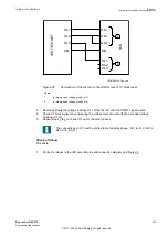


Testing with 1 Unbalance Curr option
GUID-201EB341-DD91-4927-A8BB-4A873E1798DB v1
1.
Set IBase1 as primary phase current and IBase2 as primary unbalance current using the setting
function GBASVAL.
2.
Set the following parameters:
•
Operation
=
ON
•
SCBConf
=
1 unbalance curr
•
tDefTrip = 5.00 s; tDefAlm = 5.00 s; tDefWrn = 5.00 s
•
IUnbal>
=
30% IB2
•
IUnbalAlm>
=
20% IB2
•
IUnbalWrn>
=
10% IB2
•
IMin
=
10% IB1
3.
Activate the RESETCOMP input to ensure that the stored values are reset to zero.
4.
The logical signals and service values for SCUCPTOC function are available on the local HMI
under:
Main menu/Tests/Function status/Unbalance protection /
CapBankCurrentUnbalance(60N, Iub>)/SCUCPTOC(60N, Iub>):x/outputs
, where x =
instance number.
5.
To store the unbalance current values, perform these steps:
Step No.
Changes after step 3
Expected output
5-a
Inject constant currents* of I
L1
= 1
∠
0° A, I
L2
=
1
∠
240° A, and I
L3
= 1
∠
120° A in secondary at
rated frequency.
IL1 should show 1000 A
IL2 and IL3 should show 0 A
since SCBConf = 1 unbalance curr
5-b
Inject I
UNBL1
= 0.2
∠
0° A in secondary at rated
frequency
IUNBL1 and IUNBCLCL1 should show 2 A
5-c**
Activate binary input TRIGCOMP for 1 s
•
The output COMPEXED should become
HIGH for 100 ms
•
The output LASTCOMP should display the
date and time of compensation
The following outputs should show the mentioned
values:
•
IMEML1 = 1000 A
•
IMEMUNBL1 = 2 A
•
IREFUNBL1 = 2 A
•
IUNBCLCL1 = 0 A
*
- CT ratios of the phase currents (1000/1 A) and unbalance currents (10/1 A). The values of IB1 and IB2 are
considered as 1000 A and 10 A, respectively. The current inputs I
L1
, I
L2
, and I
L3
refer to the phase current
inputs and I
UNBL1
refer to the unbalance current inputs.
**
- This step should be done only during Factory Acceptance Test (FAT). At field, the testing should be done
with the stored field values.
6.
Check the respective operation of warning, alarm, and trip.
Step No.
Changes after step 5
Expected output
WARNING TEST
6-a
Retain constant currents* of I
L1
= 1
∠
0°
A, I
L2
= 1
∠
240° A, and I
L3
= 1
∠
120° A in
secondary at rated frequency.
Change I
UNBL1UNBˍA
= 0.35
∠
0° A
WARNING and WRNL1 signals should become HIGH
after the set time delay
IUNBL1 = 3.5 A
IUNBCLCL1 = 1.5 A which is equivalent to 15% of
IBase2
ALARM TEST
Table continues on next page
Section 11
1MRK 511 403-UEN Rev. L
Testing functionality by secondary injection
132
Bay control REC670
Commissioning manual
© 2017 - 2022 Hitachi Energy. All rights reserved
Содержание REC670
Страница 1: ...Relion 670 SERIES Bay control REC670 Version 2 2 IEC Commissioning manual ...
Страница 2: ......
Страница 28: ...22 ...
Страница 54: ...48 ...
Страница 60: ...54 ...
Страница 66: ...60 ...
Страница 90: ...84 ...
Страница 212: ...206 ...
Страница 218: ...212 ...
Страница 232: ...226 ...
Страница 240: ...234 ...
Страница 241: ...235 ...