background image

Schematic  Diagrams

B - 2

B.Schematic Diagrams

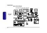
System Block Diagram

Sheet 1 of 29

System Block 

Diagram

INTEL ICH4

421 BGA

Sec. IDE

AC'97 LINK

Montara-GML

GMCH 732

uFCBGA

PCI BUS

Pri. IDE

HUB LINK

Pentium 4

Processor-M

SM BUS

H.D.D.

TI-43AB21

PCMCIA SOCKET*1

RJ-45

4-Pin

LAN

RTL8100B

Wireless Lan

AC'97

CODEC

AUDIO

AMP.

LCD CONN(LVDS)

DDR SDRAM SOCKET

MEMORY

TERMINATIONS

SO-DIMM0

SO-DIMM1

CRT OUT

LVDS

RJ-11

MDC CONN.

SM BUS

(TI-TPA0132)

(ALC201)

MDC

MODULE

USB*2

USB2

CARD

BUS

TI-1410

KBC CONN

CPU

CORE

POEWR

(VCORE)

ACIN;POWER

BUTTON

CLOCK

GEN.

USB2.0

CD-ROM/DVD/CD-RW

(50 Pin)

SYSTEM

BIOS

ISA

LPC BUS

W83517

(Option)

(PCI-1)

(PCI-2)

(PCI-3)

Charger

DC/DC BD

DDR VR

CLEVO M300N System Block Diagram

P4-M/MONTARA-GML/ICH4

KB CTRL.

H8

TOUCH PAD

CONN

BATTERY

TEMP

SENSOR

CPU

FAN

33MHz

ATA-100

478 uFCPGA

PG3,4

CCD

BT

TV OUT

CH7011

MIC

IN

SPK

OUT

SPDIF

OUT

71-M3008

USB1

AUDIO CONN.

AUDIO ADAPTOR BD.

HRS

Содержание M300N

Страница 1: ......

Страница 2: ...Preface I Preface Notebook Computer M300N M310N Service Manual ...

Страница 3: ... or in part be reproduced translated transmitted or reduced to any machine readable form without prior consent from the vendor manufacturer or creators of this publica tion except for copies kept by the user for backup purposes Brand and product names mentioned in this publication may or may not be copyrights and or registered trademarks of their respective companies They are mentioned for identif...

Страница 4: ...rvicing and or upgrading components of the M300N M310N series notebook PC The following information is included Chapter 1 Introduction provides general information about the location of system elements and their specifications Chapter 2 Disassembly provides step by step instructions for disassembling parts and subsystems and how to upgrade elements of the system Appendix A Part Lists Appendix B Sc...

Страница 5: ... an electrical storm There may be a remote risk of elec trical shock from lightning 3 Do not use the telephone to report a gas leak in the vicinity of the leak 4 Use only the power cord and batteries indicated in this manual Do not dispose of batteries in a fire They may explode Check with local codes for possible special disposal instructions 5 This product is intended to be supplied by a Listed ...

Страница 6: ... down properly and don t forget to save your work Remember to periodically save your data as data may be lost if the battery is depleted Do not expose the computer to any shock or vibration Do not place it on an unstable surface Do not place anything heavy on the computer Do not expose it to excessive heat or direct sunlight Do not leave it in a place where foreign matter or mois ture may affect t...

Страница 7: ... its purpose If you do not have access to a compatible outlet have a qualified electrician install one When you want to unplug the power cord be sure to disconnect it by the plug head not by its wire Make sure the socket and any extension cord s you use can support the total current load of all the connected devices Before cleaning the computer make sure it is disconnected from any external power ...

Страница 8: ...led or discarded Keep the battery away from metal appliances Affix tape to the battery contacts before disposing of the battery Do not touch the battery contacts with your hands or metal objects Battery Disposal The product that you have purchased contains a rechargeable battery The battery is recyclable At the end of its useful life under various state and local laws it may be illegal to dispose ...

Страница 9: ...ng manual for additional information User s Manual on CD This describes the notebook PC s features and the procedures for operating the computer and its ROM based setup pro gram It also describes the installation and operation of the utility programs provided with the notebook PC ...

Страница 10: ...Mainboard Overview Bottom Key Parts 1 10 Mainboard Overview Top Connectors 1 11 Mainboard Overview Bottom Connectors 1 12 Disassembly 2 1 Overview 2 1 Maintenance Tools 2 2 Connections 2 2 Maintenance Precautions 2 3 Disassembly Steps 2 4 Removing the Battery 2 7 Removing the Hard Disk Drive and Wireless LAN 2 8 Removing the System Memory RAM 2 10 Removing the CD Device 2 12 Removing the Modem 2 1...

Страница 11: ...Drive TEAC SAMSUNG M310N A 22 DVD ROM Drive QSI M310N A 23 DVD ROM Drive TEAC M310N A 24 Schematic Diagrams B 1 System Block Diagram B 2 Socket 478 1 of 2 B 3 Socket 478 2 of 2 B 4 Montara GM 1 B 5 Montara GM 2 B 6 Montara GM 3 B 7 DDRAM B 8 DDR Termination B 9 Clock Generator B 10 LVDS CRT B 11 ICH4 1 1 of 3 B 12 ICH4 2 2 of 3 B 13 ICH4 3 3 of 3 B 14 USB 2 0 Wireless LAN B 15 MDC BT CCT B 16 HDD ...

Страница 12: ...perating systems e g DOS Windows 9x Windows NT 4 0 Windows 2000 Windows XP OS 2 Warp UNIX etc have their own manuals as do application software e g word processing and database programs If you have questions about those programs you should consult those manuals The M300N M310N series notebook is designed to be upgradeable See Disassembly on page 2 1 for a detailed de scription of the upgrade proce...

Страница 13: ...liant ACPI 2 0 Compliant Security Security Kensington Type Lock Slot BIOS Password Memory Two 200 pin SODIMM sockets supporting DDR modules Memory expandable up to 1GB 128 256 512 MB DDR modules BIOS One 512KB Flash ROM Insyde BIOS Plug and Play 1 0a LCD 14 1 XGA Flat Panel TFT 1024 768 Display Dynamic Video Memory Technology 128 bit 2D 3D Graphics Engine Motion Compensation for DVD Accelerator Fu...

Страница 14: ...thernet One DC in jack Communication 56K Plug Play Fax Modem V 90 Compliant 10M 100M Fast Ethernet IEEE 802 3 and 802 3u Stand ard Compliant PC Camera with USB Interface optional 802 11b Module with USB Interface optional Bluetooth 1 1 with MDC Interface optional Power Management Supports ACPI 2 0 Power Button as Sleep Resume Key Supports Hibernate Mode Supports Standby Mode Supports Battery Low S...

Страница 15: ... with 14 1 LCD 6 Cell Battery Pack Optional Standard Smart Lithium Ion 65Watt Battery Pack 802 11b Module with USB Interface Bluetooth 1 1 MDC Module 2 5 12 5 12 7mm Height Hard Disk Drive PC Camera with USB Interface Design Differences This manual refers to the two notebook designs pictured below The designs vary slightly in external design Photographs used throughout this manual are of Design I ...

Страница 16: ...r Top View Figure 2 Top View 1 Optional Built In USB Camera 2 LCD 3 LED Power Communication Indicators 4 Speakers 5 Close Cover Switch 6 LED Status Indicators 7 Power Button 8 Keyboard 9 Built In Microphone 10 TouchPad and Buttons 11 Hot Key Buttons 2 6 3 5 1 7 9 8 10 11 4 4 ...

Страница 17: ... Front Left Side Views Figure 3 Front View 1 LCD Latches 2 Hot Key Buttons 1 2 1 Figure 4 Left Side View 1 Vent 2 External Monitor CRT Port 3 S Video Out Port 4 RJ 11 Phone Jack 5 RJ 45 LAN Jack 6 2 USB 2 0 Port 7 IEEE 1394 Port 8 PC Card Slot Eject Button 9 PC Card Slot 3 8 1 9 2 4 5 6 7 ...

Страница 18: ...ear Views 1 7 1 Introduction External Locator Right Side Rear Views 5 1 2 3 4 Figure 5 Right Side View 1 Microphone In Jack 2 Headphone Out Jack 3 S P DIF Out Port 4 CD Device Bay 5 DC In Jack Figure 6 Rear View 1 Security Lock Slot 2 Vent 1 2 ...

Страница 19: ...m View Figure 7 Bottom View 1 Vent Fan Outlets 2 Battery 3 CPU Cover 4 RAM Modem Cover 5 CD Device Removal Cover 6 Hard Disk WLAN Cover Note The RAM cards are located un der the RAM Mo dem Cover while the optional Wireless LAN module is lo cated under the Hard Disk Cover 1 6 2 4 5 3 1 ...

Страница 20: ...nboard Overview Top Key Parts Figure 8 Mainboard Top Key Parts 1 PC Card Assembly 2 LAN Controller RTL8100BL 3 Southbridge Intel 82801DB 4 Northbridge Intel 82852GM 5 H8 Keyboard Controller 6 TV Out Controller 7 V Core Power IC 8 Super I O Winbond 83517 1 2 3 4 5 6 7 8 ...

Страница 21: ...rd Overview Bottom Key Parts Figure 9 Mainboard Bottom Key Parts 1 Memory Sockets no memory installed 2 CPU Socket no CPU installed 3 Clock Generator 4 BIOS EEPROM 5 LAN Transformer 6 CardBus ENE 1410 7 1394 PHY TSB41LV01 8 ALC202 Audio Codec 9 Audio Amplifier 1 2 3 4 5 6 7 8 9 ...

Страница 22: ...Introduction Mainboard Overview Top Connectors 1 11 1 Introduction Mainboard Overview Top Connectors Figure 10 Mainboard Top Connectors 1 TouchPad Cable Connector JTP1 2 Keyboard Connector JKB1 1 2 ...

Страница 23: ...Hard Disk Connector JHDD1 7 Wireless LAN Cable Connector JWLAN1 8 Audio Board Cable Connector JAUDIO1 9 Int MIC JMIC1 10 1394 Connector 11 USB Connector JUSB1 JUSB2 12 Int Speaker Cable Connector JSPK1 13 LAN Connector JMLAN1 14 Modem Cable Connector JMODEM1 15 TV Out Connector JSVIDEO1 16 VGA Out Connector JVGA1 17 Inverter Connector JINV1 18 LCD LVDS Connector JLCD1 19 Fan Cable Connector JFAN1 ...

Страница 24: ...y process easier each section may have a box in the page margin Information contained under the figure will give a synopsis of the sequence of procedures involved in the disassembly procedure A box with a lists the relevant parts you will have after the disassembly process is complete Note The parts listed will be for the dis assembly procedure listed ONLY and not any previous disassembly step s r...

Страница 25: ...c ing the connection make sure the connector is oriented in the same way The pin1 side is usually not indicated Pressure sockets for multi wire connectors To release this connector type grasp it at its head and gently rock it from side to side as you pull it out Do not pull on the wires themselves When replacing the connection do not try to force it The socket only fits one way Pressure sockets fo...

Страница 26: ... Do not pull on the wire 6 Peripherals Turn off and detach any peripherals 7 Beware of static discharge ICs such as the CPU and main support chips are vulnerable to static electricity Before handling any part in the computer discharge any static electricity inside the computer When handling a printed circuit board do not use gloves or other materials which allow static electricity buildup We sugge...

Страница 27: ...the CD device page 2 12 To remove the Modem 1 Remove the battery page 2 7 2 Remove the modem page 2 13 To remove the Processor 1 Remove the battery page 2 7 2 Remove the processor page 2 14 To remove the Keyboard 1 Remove the battery page 2 7 2 Remove the keyboard page 2 16 To remove the Bottom Case 1 Remove the battery page 2 7 2 Remove the HDD WLAN page 2 8 3 Remove the system memory page 2 10 4...

Страница 28: ...d page 2 20 To remove the TouchPad Click Board 1 Remove the battery page 2 7 2 Remove the HDD WLAN page 2 8 3 Remove the system memory page 2 10 4 Remove the CD device page 2 12 5 Remove the modem page 2 13 6 Remove the processor page 2 14 7 Remove the keyboard page 2 16 8 Remove the bottom case page 2 17 9 Remove the audioboard page 2 18 10 Remove the multi function board page 2 19 11 Remove the ...

Страница 29: ... 8 3 Remove the CD device page 2 12 4 Remove the processor page 2 14 5 Remove the bottom case page 2 17 6 Remove the multi function board page 2 19 7 Remove the inverter page 2 22 8 Remove the LCD panel page 2 24 To remove the PC Camera 1 Remove the battery page 2 7 2 Remove the inverter page 2 22 3 Remove the PC Camera page 2 24 ...

Страница 30: ... 2 Locate the battery release latch Figure 1a 3 Latch should slide to the left and you will need to hold it in place Figure 1b 4 Slide the Battery out Figure 1c 2 Battery 1 1 2 1 a 2 b c Figure 1 Battery Removal a Locate the battery re lease latch b Slide the latch to the left and and hold c Slide the battery out ...

Страница 31: ... 2 7 and turn it over 2 Remove screws Figure 2a and remove the hard disk cover 3 Disconnect cables from the wireless LAN module Figure 2c Figure 2 HDD Assembly Wireless LAN Removal a Remove the 2 screws b Remove the cover c Disconnect the cables from the Wireless LAN module 1 2 3 4 5 3 Hard Disk Cover 2 Screws 1 4 3 2 HDD System Warning New HDD s are blank Be fore you begin make sure You have back...

Страница 32: ... LAN module as indicated by the arrow Figure 3c 7 Separate the Wireless LAN module and HDD assembly Figure 3d 8 Reverse the process to install a new hard disk 1 2 3 4 1 3 2 a c d b 4 Figure 3 HDD Assembly Wireless LAN Removal Cont a Slide out the HDD as sembly b Lift the HDD assembly out of the bay c Slide out the Wireless LAN module d Separate the Wireless LAN module and HDD assembly 2 Hard Disk ...

Страница 33: ... size is automatically detected by the POST routine once you turn on your computer Memory Upgrade Process 1 Turn off the computer remove the battery page 2 7 and turn it over 2 Remove screws Figure 4a from the memory socket cover 3 Carefully lift up the memory socket cover off the computer Figure 4b 4 If there is a module currently installed which needs to be upgraded replaced then remove it Figur...

Страница 34: ...s seated as far into the slot as it will go DO NOT FORCE IT it should fit without much pressure 10 Press the module down towards the mainboard until the slot levers click into place to secure the module 11 Replace the memory socket cover and the 4 screws see page 2 10 12 Restart the computer 13 The BIOS will register the new memory configuration as it starts up 1 2 1 2 3 a Figure 5 Removing Instal...

Страница 35: ...nt Figure 6c 4 Insert the new device and carefully slide it into the computer the device only fits one way DO NOT FORCE IT The screw holes should line up 5 Replace the CD device removal cover and the screw 6 Restart the computer to allow it to automatically detect the new device 1 2 Figure 6 CD Device Removal a Remove the screws b Carefully lift the cover off the computer c Push the CD device out ...

Страница 36: ...fully lift up the memory socket cover off the computer 4 Remove screws Figure 7b and carefully disconnect cables and connector 5 Lift the modeme Figure 7d off the computer 1 4 5 Figure 7 Modem Removal a Remove the screws b Lift the cover off the computer c Carefully disconnect the cables and connector d Remove the modem 6 7 8 9 10 11 6 a b 8 c d 11 7 5 9 4 3 1 2 10 5 Socket Cover 11 Modem 6 Screws...

Страница 37: ... 3 Carefully lift up the CPU cover off the computer 4 Remove screws Figure 8c from the heat sink 5 Carefully lift up the heat sink Figure 8d off the computer 1 2 3 4 6 7 Figure 8 Processor Removal a Remove the screws b Carefully lift the cover off the computer c Remove the screws in the order indicated d Remove the heat sink 3 CPU Cover 7 Heat Sink 5 Screws 1 2 5 4 6 a c b 3 d 7 ...

Страница 38: ... 9b 8 When re inserting the CPU play careful attention to the pin alignment it will fit only one way don t force it 1 2 Figure 9 Processor Removal cont d a Raise the latch to unlock the CPU b Lift the CPU out of the socket 1 a 2 b Locked Caution The heat sink and CPU area in general contains parts which are subject to high temperatures Allow the area time to cool before removing these parts 2 CPU ...

Страница 39: ...ed to use a small screwdriver to do this 3 Carefully lift the keyboard up and out being careful not to bend the keyboard ribbon cable Figure 10b 4 Disconnect the keyboard ribbon cable from the locking collar socket Figure 10b and lift the keyboard up out of the computer 1 2 3 Figure 10 Keyboard Removal a Press the latches to ele vate the keyboard b Disconnect the keyboard cable form the locking co...

Страница 40: ...t of the computer Figure 11c and remove screws Figure 11d 5 Carefully lift the bottom case off the LCD and top case assembly Figure 11e Figure 11 LCD Bottom Case Removal a Remove the screws from the bottom of the compu ter b Remove the screws and disconnect the cables c Lift the fan shield cover d Remove the screws from the side of the computer e Lift the bottom case off the LCD and top case assem...

Страница 41: ...rd disk page 2 8 CD Device page 2 12 CPU page 2 14 and bottom case page 2 17 2 Remove screws and disconnect cables 3 Lift the audioboard off the mainboard assembly Figure 14b 5 Audioboard 2 Screws Figure 12 Audioboard Removal a Remove screws and dis connect the cables d Lift the audioboard off the mainboard 1 2 3 4 5 4 a b 1 2 3 5 6 ...

Страница 42: ...ge 2 14 and bottom case page 2 17 2 Remove screws and disconnect cables Figure 14a 3 Lift the multi function board and bracket off the mainboard assembly Figure 14b 5 Multi function board 10 Bracket 2 Screws Figure 13 Multi function board Removal a Remove screws and dis connect the cables d Lift the multi function board and bracket off the mainboard assembly 1 2 3 8 9 10 7 a b 1 2 3 9 10 5 8 6 4 ...

Страница 43: ...ews and lift the DC DC board from the mainboard 3 Disconnect cables and remove screws Figure 14c 4 Separate the mainboard and top case Disconnect the TouchPad cable Figure 14d 4 DC DC board 5 Mainboard 16 Bottom case 5 Screws Figure 14 Mainboard Removal a Remove screws b Lift the DC DC board off the mainboard c Disconnect the cables and remove the screws d Separate the mainboard and top case Disco...

Страница 44: ...ge 2 20 2 Remove screws Figure 15a and disconnect cables from the click board assembly and lift the assembly off the top case Figure 15b 3 Remove screws Figure 15c 4 Lift the TouchPad off the top case and separate the TouchPad from its casing Figure 15d Figure 15 TouchPad and Click Board Removal a Remove the screws b Separate the click board from the top case c Remove the screws d Separate the tou...

Страница 45: ...l module from the back 4 Remove screw from the inverter over and disconnect the cables from the rear of the inverter 5 Lift the inverter off the LCD assembly Figure 16d 5 LCD Front Panel 9 Inverter 4 Rubber covers 5 Screws Figure 16 Inverter Removal a Remove the rubber cov ers and screws b Unsnap the frame from the LCD front panel module c Remove screw from in verter and disconnect the cables c Li...

Страница 46: ...e page 2 12 CPU page 2 14 bottom case page 2 17 mainboard page 2 20 and inverter page 2 22 2 Remove the screws Figure 17a from the speakers 3 Separate the speakers Figure 17b from the LCD front panel assembly 5 Speakers 4 Screws Figure 17 Speakers Removal a Remove the screws b Separate the speakers from the LCD front panel assembly 1 4 5 4 3 5 a b 5 1 2 ...

Страница 47: ...nel off the LCD assembly Figure 18b Removing the PC Camera Module 1 Turn off the computer remove the battery page 2 7 and inverter page 2 22 2 Disconnect cable from the PC camera module Figure 19a 3 Lift the PC camera module Figure 19b off the LCD assembly 7 LCD Panel 4 Screws Figure 18 LCD Panel Removal a Remove screws from the side of the LCD panel b Lift the LCD panel off the LCD assembly 1 4 7...

Страница 48: ... numbers Your organization may use a different system so be sure to cross check any relevant documentation Note Some assemblies may have parts in common especially screws However the part lists DO NOT indicate the total number of duplicated parts used Note Be sure to check any update notices The parts shown in these illustrations are appropriate for the system at the time of publication Over the p...

Страница 49: ...ion Location Part M300N M310N Top page A 3 page A 14 Bottom page A 4 page A 15 LCD page A 5 page A 16 CD ROM Drive QSI page A 6 page A 17 CD ROM Drive SAMSUNG page A 7 page A 18 CD RW Drive KME page A 8 page A 19 CD RW Drive TEAC page A 9 page A 20 Combo Drive QSI page A 10 page A 21 Combo Drive TEAC SAMSUNG page A 11 page A 22 DVD ROM Drive QSI page A 12 page A 23 DVD ROM Drive TEAC page A 13 pag...

Страница 50: ...Part Lists Top M300N A 3 A Part Lists Top M300N Figure 1 Top M300N ...

Страница 51: ...Part Lists A 4 Bottom M300N A Part Lists Bottom M300N Figure 2 Bottom M300N ...

Страница 52: ...Part Lists LCD M300N A 5 A Part Lists LCD M300N Figure 3 LCD M300N ...

Страница 53: ...Part Lists A 6 CD ROM Drive QSI M300N A Part Lists CD ROM Drive QSI M300N Figure 4 CD ROM Drive QSI M300N ...

Страница 54: ...Part Lists CD ROM Drive SAMSUNG M300N A 7 A Part Lists CD ROM Drive SAMSUNG M300N Figure 5 CD ROM Drive SAMSUNG M300N ...

Страница 55: ...Part Lists A 8 CD RW Drive KME M300N A Part Lists CD RW Drive KME M300N Figure 6 CD RW Drive KME M300N ...

Страница 56: ...Part Lists CD RW Drive TEAC M300N A 9 A Part Lists CD RW Drive TEAC M300N Figure 7 CD RW Drive TEAC M300N ...

Страница 57: ...Part Lists A 10 Combo Drive QSI M300N A Part Lists Combo Drive QSI M300N Figure 8 Combo Drive QSI M300N ...

Страница 58: ...Part Lists Combo Drive TEAC SAMSUNG M300N A 11 A Part Lists Combo Drive TEAC SAMSUNG M300N Figure 9 Combo Drive TEAC SAMSUNG M300N ...

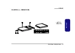
Страница 59: ...Part Lists A 12 DVD ROM Drive QSI M300N A Part Lists DVD ROM Drive QSI M300N Figure 10 DVD ROM Drive QSI M300N ...

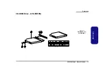
Страница 60: ...Part Lists DVD ROM Drive TEAC M300N A 13 A Part Lists DVD ROM Drive TEAC M300N Figure 11 DVD ROM Drive TEAC M300N ...

Страница 61: ...Part Lists A 14 Top M310N A Part Lists Top M310N Figure 12 Top M310N ...

Страница 62: ...Part Lists Bottom M310N A 15 A Part Lists Bottom M310N Figure 13 Bottom M310N ...

Страница 63: ...Part Lists A 16 LCD M310N A Part Lists LCD M310N Figure 14 LCD M310N ...

Страница 64: ...Part Lists CD ROM Drive QSI M310N A 17 A Part Lists CD ROM Drive QSI M310N Figure 15 CD ROM Drive QSI M310N ...

Страница 65: ...Part Lists A 18 CD ROM Drive SAMSUNG M310N A Part Lists CD ROM Drive SAMSUNG M310N Figure 16 CD ROM Drive SAMSUNG M310N ...

Страница 66: ...Part Lists CD RW Drive KME M310N A 19 A Part Lists CD RW Drive KME M310N Figure 17 CD RW Drive KME M310N ...

Страница 67: ...Part Lists A 20 CD RW Drive TEAC M310N A Part Lists CD RW Drive TEAC M310N Figure 18 CD RW Drive TEAC M310N ...

Страница 68: ...Part Lists Combo Drive QSI M310N A 21 A Part Lists Combo Drive QSI M310N Figure 19 Combo Drive QSI M310N ...

Страница 69: ...Part Lists A 22 Combo Drive TEAC SAMSUNG M310N A Part Lists Combo Drive TEAC SAMSUNG M310N Figure 20 Combo Drive TEAC SAMSUNG M310N ...

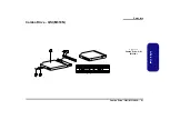
Страница 70: ...Part Lists DVD ROM Drive QSI M310N A 23 A Part Lists DVD ROM Drive QSI M310N Figure 21 DVD ROM Drive QSI M310N ...

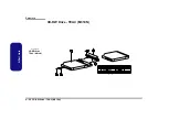
Страница 71: ...Part Lists A 24 DVD ROM Drive TEAC M310N A Part Lists DVD ROM Drive TEAC M310N Figure 22 DVD ROM Drive TEAC M310N ...

Страница 72: ...OM W517 Page B 19 Montara GM 1 Page B 5 TI1394 TSB43AB21 Page B 20 Montara GM 2 Page B 6 Hitachi H8S Page B 21 Montara GM 3 Page B 7 CON Page B 22 DDRAM Page B 8 Audio Codec ALC201 Page B 23 DDR Termination Page B 9 PCMCIA ENE1410 Page B 24 Clock Generator Page B 10 PCMCIA Socket Page B 25 LVDS CRT Page B 11 AC IN Power Button Page B 26 ICH4 1 1 of 3 Page B 12 CH7011 TV Out Page B 27 ICH4 2 2 of 3...

Страница 73: ...SOCKET MEMORY TERMINATIONS SO DIMM0 SO DIMM1 CRT OUT LVDS RJ 11 MDC CONN SM BUS TI TPA0132 ALC201 MDC MODULE USB 2 USB2 CARD BUS TI 1410 KBC CONN CPU CORE POEWR VCORE ACIN POWER BUTTON CLOCK GEN USB2 0 CD ROM DVD CD RW 50 Pin SYSTEM BIOS ISA LPC BUS W83517 Option PCI 1 PCI 2 PCI 3 Charger DC DC BD DDR VR CLEVO M300N System Block Diagram P4 M MONTARA GML ICH4 KB CTRL H8 TOUCH PAD CONN BATTERY TEMP ...

Страница 74: ... AA4 AA7 AA9 AA11 AA13 AA15 AA17 AA19 AA23 AA26 AB3 AB6 AB8 AB10 AB12 AB14 AB16 AB18 AB20 AB21 AB24 AF25 A7 AD2 AF24 AF3 AD3 A22 AE21 VSS VSS VSS VSS VSS VSS VSS VSS VSS VSS VSS VSS VSS VSS VSS VSS VSS VSS VSS VSS VSS VSS VSS VSS VSS VSS VSS VSS VSS VSS VSS VSS VSS VSS VSS VSS VSS VSS VSS VSS VSS VSS VSS VSS VSS VSS VSS VSS VSS VSS VSS VSS VSS VCC_SENSE VSS_SENSE TESTHI0 TESTHI1 TESTHI2 TESTHI3 TE...

Страница 75: ...6 1K T T T T T T T R535 4 7K R14 10K R308 62 1 R31 100_1 R530 10K R531 10K Q29 3904 B E C Q30 3904 B E C R30 49 9_1 U23 MIC5258 1 2 3 4 5 VIN GND EN PG VOUT R16 200 R313 200 R333 200 R329 200 R331 200 R334 200 R335 200 R311 200 C20 220p 6 3V C19 220p 6 3V R35 49 9_1 R34 100_1 R330 62_1 T T T T T T T R12 0 R39 0 C24 0 1uF_X7R R283 47K C10 1uF_X7R R332 62_1 R338 0 R6 300_1 R4 51_1 R326 51_1 R1 150 N...

Страница 76: ...ntara GMCH AF2 AE3 AF4 AH2 AD3 AE2 AG4 AH3 AD6 AG5 AG7 AE8 AF5 AH4 AF7 AH6 AF8 AG8 AH9 AG10 AH7 AD9 AF10 AE11 AH10 AH11 AG13 AF14 AG11 AD12 AF13 AH13 AH16 AG17 AF19 AE20 AD18 AE18 AH18 AG19 AH20 AG20 AF22 AH22 AF20 AH19 AH21 AG22 AE23 AH23 AE24 AH25 AG23 AF23 AF25 AG25 AH26 AE26 AG28 AF28 AG26 AF26 AE27 AD27 AG14 AE14 AE17 AG16 AH14 AE15 AF16 AF17 AJ24 AG2 AH5 AH8 AE12 AH17 AE21 AH24 AH27 AD15 AC1...

Страница 77: ...2 W1 K22 H27 K25 L24 J27 G28 L27 L23 L25 J24 H25 K23 G27 K26 J23 H26 F25 F26 B27 H23 E27 G25 F28 D27 G24 C28 B26 G22 C26 E26 G23 B28 B21 G21 C24 C23 D22 C25 E24 D24 G20 E23 B22 B23 F23 F21 C20 C21 G18 E19 E20 G17 D20 F19 C19 C17 F17 B19 G16 E16 C16 E17 D16 C18 L28 M25 N24 M28 N28 N27 P27 M23 N25 M26 P28 N23 P26 M27 HA3 HA4 HA5 HA6 HA7 HA8 HA9 HA10 HA11 HA12 HA13 HA14 HA15 HA16 HA17 HA18 HA19 HA20 ...

Страница 78: ...3 0 01uF C329 220uF C304 0 1uF C82 10uF C96 0 1uF C80 0 1uF C99 0 1uF C315 470uF C333 10uF C399 150uF C302 0 1uF L40 HCB1608K 121T25 C105 0 1uF C69 0 1uF C95 0 1uF C66 0 1uF C101 0 1uF C90 0 1uF C94 0 1uF C103 0 1uF C85 0 1uF L19 HCB1608K 121T25 C93 0 1uF C87 0 1uF C76 0 1uF C65 0 1uF C104 0 1uF C307 0 1uF C73 0 1uF R135 1 C397 4 7uF C403 0 1uF C117 0 1uF C100 0 1uF C116 0 1uF C354 150uF C331 47uF...

Страница 79: ...30 32 41 43 49 53 42 44 50 54 55 59 65 67 56 60 66 68 127 129 135 139 128 130 136 140 141 145 151 153 142 146 152 154 163 165 171 175 164 166 172 176 177 181 187 189 178 182 188 190 9 10 21 22 33 34 36 45 46 57 58 69 70 81 82 92 93 94 113 114 131 132 143 144 155 156 157 167 168 179 180 191 192 3 4 15 16 27 28 38 39 40 51 52 63 64 75 76 87 88 90 103 104 125 126 137 138 149 150 159 161 162 173 174 1...

Страница 80: ...ATA9 M_DATA_R_8 M_CB_R0 M_DATA_R_39 M_DQS1 M_CB6 M_DATA_R_1 M_DATA1 M_AA3 M_AA_FR_10 M_DATA_R_2 M_CB5 M_DM8 M_DATA39 M_CB1 M_DM5 M_AA0 M_DM_R_5 M_DATA_R_11 M_DATA_R_17 M_DQS8 M_CB_R2 M_DATA_R_32 M_DATA33 M_DATA32 M_DATA_R_33 M_DQS_R4 M_DQS4 M_DATA_R_38 M_DM4 M_DM_R_4 M_DATA38 M_DATA_R_36 M_DATA37 M_DATA36 M_DATA34 M_DATA_R_34 M_DATA_R_37 M_AB5 M_AB4 M_AA4 M_AA5 M_AA2 M_AA1 M_AB1 M_AB2 M_DATA_R_13 ...

Страница 81: ...R361 1M R340 1K Y1 14 318MHZ 1 2 C334 33P C312 33P R44 49 9_1 U4 ICS950810 TSSOP 4 9 15 20 27 31 36 41 47 46 53 1 8 14 19 32 26 28 23 24 49 56 10 11 12 13 16 17 18 54 55 5 29 39 38 25 33 35 21 22 34 42 45 48 51 44 40 50 52 7 30 2 6 43 3 37 GND GND GND GND GND GND GND GND GND VDDCPU CPU_STOP VDDREF VDDPCI VDDPCI VDD3V66 VDD3V66 VDDA VTT_PWRGD 3V66_4 66MHz_OUT2 3V66_5 66MHz_IN CPUCLKT1 REF PCICLK0 P...

Страница 82: ...Z1115 C34 10uF 25V R64 4 7K R358 4 7K U24A 74HCT125 2 3 14 1 7 U24B 74HCT125 5 6 14 4 7 LP1 8P4LXFCM1608K 121T06 1 2 3 4 5 6 7 8 JINV1 CON12 1 2 3 4 5 6 7 8 9 10 11 12 D2 RB751V A C R517 0 R66 15K R46 15K L6 HCB2012K 500T40 1 2 R357 75 R349 75 R342 75 C33 0 1uF C37 22PF C39 22PF C40 22PF C289 220PF C310 22PF C283 1000PF C41 1000PF RP38 8P4RX4 7K 8 1 7 2 6 5 3 4 L9 FCM1608K 121T06 1 2 C299 22PF C35...

Страница 83: ...4 J5 K2 G2 L1 G4 L2 H2 L3 F5 F4 N1 E5 N2 E3 N3 E4 M5 E2 P1 E1 P2 D3 R1 D2 P4 J2 K4 M4 N4 C1 E6 A7 B7 D6 B1 A2 B3 C7 B6 P5 M3 F1 B5 A6 E8 C5 L5 G1 L4 M2 W2 U5 K5 F3 F2 W6 AC3 AB1 AC4 AB4 AA5 Y22 AB23 U23 AA21 W21 V22 AB22 V21 Y23 U22 U21 W23 V23 L19 L20 M19 M21 P19 R19 T20 R20 P23 L22 N22 K21 T21 N20 P21 R23 M23 R22 J19 H19 K20 D5 C2 B4 A3 C8 D7 C3 C4 AC13 AA19 J22 D10 D11 A8 C12 A10 A9 A11 B10 C10...

Страница 84: ...6 1K ICH4 M PART B Power Management IST AC 97 I F LPC I F USB I F GPIO Unmaxed GPIO IDE I F Clocks Misc BGA2B ICH4 M R2 Y3 AB2 T3 AC2 V20 AA1 Y1 AB6 AA6 W18 Y4 Y2 AA2 W19 Y21 AA4 AB3 V1 J21 Y20 V19 B8 C13 D13 A13 B13 D9 C9 T2 R4 T4 U2 U3 U4 T5 C20 A21 C18 A19 C16 A17 D20 B21 D18 B19 D16 B17 B15 C14 A15 B14 A14 D14 A23 B23 J20 G22 F20 G20 F21 H20 F23 H22 G23 H21 F22 E23 R3 V4 V5 W3 V2 W1 W4 Y13 AB1...

Страница 85: ...74 8 2K R167 8 2K R158 8 2K R166 8 2K R143 8 2K R171 8 2K R170 8 2K R159 8 2K R169 8 2K R156 8 2K R175 8 2K R161 8 2K R172 8 2K R177 8 2K R128 8 2K R138 8 2K R157 8 2K R146 8 2K R176 8 2K R439 8 2K C143 0 1uF C377 0 1uF C124 0 1uF R186 8 2K R211 100K R197 8 2K C380 0 1uF C381 0 01uF L58 HCB1608K 121T25 R181 2 2K R163 2 2K R153 100K C139 0 1uF C151 22uF C420 22uF C142 0 1uF C120 0 1uF C129 0 1uF C1...

Страница 86: ...ND3 GND4 VCC DATA DATA GND S S S S C475 47PF R526 470K R527 560K C433 0 1uF C160 100uF 25V C573 1000PF F1 FUSE_1210 1 2 L64 HCB1608K 121T25 L22 PWC1206ST161T 1 4 2 3 C434 47PF C158 22PF R207 0 R205 0 U17 DIODE 1A C A C432 47PF U15 DIODE 1A C A L62 HCB1608K 121T25 R528 470K F2 FUSE_1210 1 2 C574 1000PF R529 560K L26 PWC1206ST161T 1 4 2 3 C162 100uF 25V C167 0 1uF JUSB2 USB_4P 1 2 3 4 GND1 GND2 GND3...

Страница 87: ...D BT_EN1 Z1611 Z1622 R423 0 C390 47PF C389 22PF R425 0 C388 47PF C284 0 1uF C568 100uF 25V C569 0 1uF U12A 74LVC14 1 2 14 7 C157 0 1uF L78 HCB1608K 121T25 C572 0 1uF R522 0 R521 0 R537 10K C589 100uF 25V_1210 C580 0 1UF JMFC1 CONN13 1 2 3 4 5 6 7 8 9 10 11 12 13 JWLAN1 CON5 1 2 3 4 5 R460 0 R223 22 JMDC1 AMP CON30 1 2 3 4 5 6 7 8 9 10 11 12 13 14 15 16 17 18 19 20 21 22 23 24 25 26 27 28 29 30 C16...

Страница 88: ...CS3 IDE_PDD3 IDE_PDA1 IDE_PDD7 IDE_PDD1 IDE_PIORDY IDE_PDD5 IDE_PDA0 IDE_PDD8 IDE_PDD15 IDE_PDIOR PDLED Z1701 INT_IRQ14 IDE_PDA2 P66CBLID IDE_SDD15 IDE_SDD3 IDE_SDD14 IDE_SDD10 IDE_SDD4 IDE_SDD8 IDE_SDD5 IDE_SDD0 IDE_SDD9 IDE_SDD12 IDE_SDD13 IDE_SDD1 IDE_SDD2 IDE_SDD6 INT_IRQ15 IDE_SDD11 IDE_PDD 0 15 IDE_SDD 0 15 PCIRST IDE_SDD8 IDE_SDD7 TZ1707 TZ1705 TZ1706 TZ1704 TZ1703 TZ1702 TZ1701 TZ1708 R240...

Страница 89: ...0 1uF R465 100 Y2 25MHz C467 10P C466 0 1uF L61 HCB2012K 121T30 R456 5 6K R450 1K R452 0 T C430 0 1uF T C409 0 1uF T R463 0 T T T T L57 FCM1608K 121T06 RTL8100B U43 RTL8100B 6 98 99 100 1 2 3 4 5 8 9 22 10 11 12 13 14 16 15 17 18 19 20 21 34 23 24 25 26 31 27 28 29 30 32 33 36 37 38 43 41 42 44 45 39 46 47 48 49 53 56 62 70 69 66 52 73 7 60 61 63 64 65 67 68 35 71 72 54 74 40 79 80 58 81 82 83 84 ...

Страница 90: ... 65 64 63 62 61 60 59 58 57 56 55 54 53 51 50 49 48 47 46 45 44 43 42 41 40 39 38 37 36 35 34 33 32 31 30 29 28 27 26 1 76 77 78 79 80 81 82 83 84 85 86 87 88 89 90 91 92 93 94 95 96 97 98 99 100 69 52 2 3 4 5 6 7 8 9 10 11 12 13 14 15 16 17 18 19 20 21 22 23 24 25 XA5 GP42 XA4 GP41 XA3 GP40 XA2 GP27 XA1 GP26 XA0 GP15 MEMW GP13 MEMR GP12 XD7 GP37 XD6 GP36 XD5 GP35 XD4 GP34 XD3 GP33 GND XD2 GP32 XD...

Страница 91: ... 8P4RX220 8 1 7 2 6 5 3 4 C201 12PF TSB43AB21 POWER CLASS OSCILLATOR PHY PORT 2 BIAS CURRENT FILTER PHY PORT 1 EEPROM 2 WIRE BUS PCI BUS INTERFACE U19 TSB43AB21 13 16 18 19 21 22 24 25 26 28 29 31 32 36 37 38 40 41 42 43 45 46 49 50 52 53 54 56 84 82 81 80 79 77 76 74 71 70 69 67 66 65 63 61 58 57 106 125 124 123 122 121 116 115 114 113 112 3 4 118 119 7 15 27 39 51 59 72 88 100 1 2 107 108 120 10...

Страница 92: ...1N4148 A C R504 10K U55 SI9183 3 3 1 2 3 4 5 VIN GND SD BP VO C565 0 1uF U12E 74LVC14 11 10 14 7 C592 10uF 10V C591 10uF 10V C590 0 1UF R87 1K T Q5 2N7002 G S D R74 10K R33 1K JFAN1 HEADER 3 1 2 3 JHDEBUG1 CON6 1 2 3 4 5 6 A B C D E F L1 HCB2012K 500T40 1 2 R130 10K D3P D12 IMN10 1 2 3 4 5 6 R110 4 7K D36 RB751V A C R388 100K R397 10K C15 10uF J80PORT1 PORT80 1 2 3 4 5 L52 FCM1608K 221T06 1 2 L51 ...

Страница 93: ... 10uF 10V JDD1 CON50 1 3 5 7 9 11 13 15 17 19 21 23 25 27 29 31 33 35 37 39 41 43 45 47 49 2 4 6 8 10 12 14 16 18 20 22 24 26 28 30 32 34 36 38 40 42 44 46 48 50 1 3 5 7 9 11 13 15 17 19 21 23 25 27 29 31 33 35 37 39 41 43 45 47 49 2 4 6 8 10 12 14 16 18 20 22 24 26 28 30 32 34 36 38 40 42 44 46 48 50 C71 0 1U C86 0 1U C97 0 1U 1 25VS 9 DD_ON 26 SUSB 4 13 18 19 26 29 DDON 21 26 ICHPWROK 4 11 12 13...

Страница 94: ...233 0 1uF C237 1000PF R274 10K Y4 24 576M 1 2 ALC201 ALC202 U20 ALC201 43 44 45 46 47 48 39 40 41 31 32 33 34 26 1 2 3 4 5 6 7 8 9 10 11 12 13 14 15 16 17 18 19 20 21 22 23 24 27 28 29 30 35 36 37 38 42 25 JD SDIN1 GPIO0 TEST1 GPIO1 ID0 XTLSEL EAPD SPDIFO HP_OUT_L NC HP_OUT_C HP_OUT_R VRAD CAP1 VRDA CAP2 CAP1 CAP3 NC CAP4 AVss1 DVdd1 XTL_IN XTL_OUT DVss1 SDATA_OUT BIT_CLK DVss2 SDATA_IN DVdd2 SYNC...

Страница 95: ...AD22 CAD21 CAD31 CAD16 CAD1 CAD27 CAD26 CAD25 CAD11 CAD6 CAD2 CAD18 CAD5 CAD4 CAD13 CAD10 CAD0 CAD19 CAD15 CAD12 CAD23 CAD8 CAD7 MFUNC1 MFUNC2 MFUNC5 MFUNC4 PCMSPK Z2401 PCI_AD 31 0 CCBE 0 3 CAD 0 31 Z2407 RP19 8P4RX10K 8 1 7 2 6 5 3 4 L68 HCB2012K 121T30 1 2 R227 4 7K L69 HCB2012K 121T30 1 2 R453 47 R220 10 C203 15P R234 75 R231 100 C154 0 1uF C436 0 1uF C479 0 1uF C161 0 1uF R221 10 C204 10uF 10...

Страница 96: ...9 30 31 32 33 34 69 70 71 72 74 75 76 73 35 36 37 38 39 40 41 42 43 44 45 46 47 48 49 50 51 52 53 54 55 56 57 58 59 60 61 62 63 64 65 66 67 68 GND D3 CAD0 D4 CAD1 D5 CAD3 D6 CAD5 D7 CAD7 CE1 CCBE0 A10 CAD9 OE CAD11 A11 CAD12 A9 CAD14 A8 CCBE1 A13 CPAR A14 CPERR WE PGM CGNT RDY BSY IRQ INT VCC VPP1 A16 CCLK A15 CIRDY A12 CCBE2 A7 CAD18 A6 CAD20 A5 CAD21 A4 CAD22 A3 CAD23 A2 CAD24 A1 CAD25 A0 CAD26 ...

Страница 97: ...K R R495 R_1210 R415 4 7K PC60 0 1uF 0805 C367 10uF 10V R301 10K PD21 RB751V A C PD22 RB751V A C Q13 DTD114EK C E B R322 10K R359 0 D34 1N4148 A C Q25 2N7002 G D S Q22 2N7002 G D S U50 AS2951 8 7 6 5 4 3 2 1 INPUT FB VCC ERROR GND S D SENSE OUTPUT Q26 1198 B E C D35 ZD5 6V A C Q23 1198 B E C C555 1uF C523 1uF_0603 R482 56K R480 10K R470 10K C548 10uF 10V D33 1N4148 A C R487 10K R481 100K R472 68K ...

Страница 98: ...6 37 38 39 3 9 1 12 49 6 11 64 45 23 29 18 44 16 17 41 20 26 32 33 34 40 46 D11 D10 D9 D8 D7 D6 D5 D4 D3 D2 D1 D0 XCLK XCLK NC H V RESET SD SC GPIO1 GPIO0 AS ISET C H Sync XI FIN XO NC NC NC NC NC NC NC NC NC BCO CVBS Y G C R CVBS B VREF NC DVDD0 DVDD1 DVDD2 DGND0 DGND1 DGND2 DVDDV NC NC AVDD0 AVDD1 AGND0 AGND1 AGND2 NC NC NC VDD GND0 GND1 Pout R71 8 2k R77 8 2k C355 33P C83 33P C78 270PF L13 FCM1...

Страница 99: ...3 22K PQ25 2N7002 G D S PR10 0 PR11 0 PR25 100K PR12 14 3K_1 PR18 0 PC14 220U D PL3 1UH 1 2 PQ23 2N7002 G D S PR7 2m 2512 PC24 330P PR9 0 PC21 0 1UF PD7 RB751V A C PR56 26 7K_1 PC27 0 1UF PR69 10K PC6 220U D PR15 0 R PQ2 SI4892 4 6 2 7 3 8 5 1 PC65 1000P PR67 237K_1 PR21 0 PQ4 SI4362 4 6 2 7 3 8 5 1 PD5 20QS04 A C PC10 220U D PQ8 SI4892 4 6 2 7 3 8 5 1 PQ3 SI4892 4 6 2 7 3 8 5 1 PC15 220U D PR62 0...

Страница 100: ...158D158 M2 M MARK1 M13 M MARK1 M11 M MARK1 M4 M MARK1 M10 M MARK1 1 H6 MTH315D111 2 3 4 5 6 7 8 9 M5 M MARK1 M3 M MARK1 M8 M MARK1 M12 M MARK1 M7 M MARK1 M6 M MARK1 1 H11 MTH315D111 2 3 4 5 6 7 8 9 1 H7 MTH315D111 2 3 4 5 6 7 8 9 PR29 2 2K PR27 2 2K PC32 0 1U 0805 1 H19 MTH315D111 2 3 4 5 6 7 8 9 1 H18 MTH315D111 2 3 4 5 6 7 8 9 1 H17 MTH315D111 2 3 4 5 6 7 8 9 1 H13 MTH315D111 2 3 4 5 6 7 8 9 PC6...

Страница 101: ...C D MC7 0 1UF MSW2 TJ G 5 3 1 4 2 5 6 MPU1 MIC6211 3 4 1 5 2 MPR7 10K 1 MPR3 100m 2512 MPR9 40 2K 1 MPR1110K 1 MPR10100K 1 MPR8 100K 1 MPR6 10K 1 MPC6 1uF 0805 MPC4 1uF 0805 MPD1 FD10JK4 TO 252 A1 A2 C MPC5 1uF 0805 MD1 LED A C 10K 10K MQ1 DTC114EUA C B E MR5 680 47K 47K MQ2 DTA114EUA C B E MD5 LED A C MR4 680 MD4 LED A C MR2 680 MR1 680 MD2 LED A C MR3 680 MC6 0 1UF ML1 HCB1608K 121T25 MM4 M MARK...

Страница 102: ... page 3 In the Driver section select the model of your computer M300N M310N Series and the driver type BIOS 4 Select GO 5 Click on M3x0NRxxx zip to download the BIOS files including BIOS refresh tools Unzip the file you have just downloaded on to a bootable floppy disk The files you should see on this disk are Flash exe Fp exe M3x0Rxxx bin 1 With the bootable floppy disk containing the BIOS files ...

Отзывы: