


L300P Inverter
Getti
n
g Star
ted
1–9
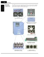
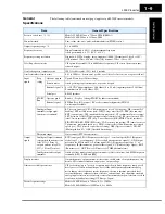
General
Specifications
The following table (continued on next page) applies to all L300P inverter models.
Item
General Specifications
Protective enclosure *1 *11
Models L300P–015xxx to 750xxx: IP20 (NEMA 1)
Models L300P–900xx to 1320xxx: IP00
Control method
Line-to-line sine wave pulse-width modulation (PWM) control
Output frequency range *4
0.1 to 400 Hz
Frequency accuracy
Digital command: ± 0.01% of the maximum frequency
Analog command: ± 0.2% (25
°
C ± 10
°
C)
Frequency setting resolution
Digital: ± 0.01 Hz; Analog: (max. frequency)/4000, [O] terminal: 12-bit, 0 to 10V;
[OI] terminal: 12-bit, 4-20mA; 12 bit [O2] terminal: 12 bit –10 to +10V
Volt./Freq. characteristic
V/F optionally variable (30 to 400Hz base frequency), V/F control (constant torque,
reduced torque)
Overload capacity (output current)
120% for 60 seconds, 150% for 0.5 seconds
Acceleration/deceleration time
0.01 to 3600 sec., (linear curve profiles, accel./decel. selection), two-stage accel./decel.
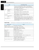
Input
signal
Freq.
setting
Operator keypad
Up and Down keys / Value settings
Potentiometer
Analog setting via potentiometer on operator keypad
External signal *8
0 to 10 VDC (input impedance 10k Ohms), 4 to 20 mA (input impedance 250 Ohms),
Potentiometer (1k to 2k Ohms, 2W)
Serial port
RS485 interface
FW/RV
Run
Operator panel
Run key / Stop key (change FW/RV by function command)
External signal
FW Run/Stop (NO contact), RV set by terminal assignment (NC/NO),
3-wire input available
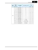
Intelligent Input
terminals (assign eight
functions to terminals)
RV (reverse run/stop), CF1~CF4 (multi-speed select), JG (jogging), DB (external DC
braking), SET (set 2nd motor data), 2CH (2-stage accel./decel.), FRS (free-run stop),
EXT (external trip), USP (unattended start protection), CS (commercial power source),
SFT (software lock), AT (analog input voltage/current select), RS (reset inverter), STA
(start, 3-wire interface), STP (stop, 3-wire interface), F/R (FW/RV 3-wire interface),
PID (PID ON/OFF), PIDC (PID reset), CAS (control gain setting), UP (remote control
Up function, motorized speed pot.), DWN (remote control Down function, motorized
speed pot.), UDC (remote control data clearing), OPE (Operator control), SF1-SF7
(Multispeed bits 0-7), OLR (Overload limit change)
Thermistor input
One terminal (PTC characteristics)
Output
signal
Intelligent Output terminals
(assign three functions to two
relay N.O. (1 Form A)
outputs and one relay N.O.-
N.C. (1 Form C) contact
RUN (run signal), FA1 (Frequency arrival type 1 – constant speed), FA2 (Frequency
arrival type 2 – over-frequency), OL (overload advance notice signal 1), OD (Output
deviation for PID control), AL (alarm signal), FA3 (Frequency arrival type 3 – at-
frequency), IP (Instantaneous power failure signal), UV (Under-voltage signal), RNT
(Run time over), ONT (Power-ON time over), THM (thermal alarm)
Intelligent monitor output
terminals
Analog voltage monitor, analog current monitor (8-bit resolution), and PWM output, on
terminals [AM], [AMI], and [FM]
Display monitor
Output frequency, output current, motor torque, scaled value of output frequency, trip
history, I/O terminal condition, input power, output voltage
Other user-settable parameters
V/F free-setting (up to 7 points), frequency upper/lower limit, frequency jump, accel/
decel curve selection, manual torque boost value and frequency adjustment, analog
meter tuning, start frequency, carrier frequency, electronic thermal protection level,
external frequency output zero/span reference, external frequency input bias start/end,
analog input selection, retry after trip, restart after instantaneous power failure, overload
restriction, default value setting (US, Europe, Japan)
Carrier frequency range
Models L300P–015xxx to 750xxx: 0.5 to 12 kHz
Models L300P–900Hxx to 1320Hxx: 0.5 to 8 kHz
Содержание L300P Series
Страница 2: ......
Страница 42: ......
Страница 134: ......
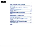
Страница 195: ...Inverter System Accessories In This Chapter page Introduction 2 Component Descriptions 3 Dynamic Braking 6 5 ...
Страница 225: ...Glossary and Bibliography In This Appendix page Glossary 2 Bibliography 6 A ...
Страница 250: ......
Страница 251: ...Drive Parameter Settings Tables In This Appendix page Introduction 2 Parameter Settings for Keypad Entry 2 C ...
Страница 263: ...CE EMC Installation Guidelines In This Appendix page CE EMC Installation Guidelines 2 Hitachi EMC Recommendations 4 D ...
Страница 272: ......


