


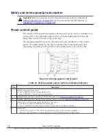


Item
Description
6
MESSAGE LED
•
Off when power is off, or when a system generated message is not in the queue, and the SVP has not
failed.
•
Amber* On when a system information message (SIM) is generated by either of the clusters and has
been sent to Device Manager - Storage Navigator and to the users that are set up in Device Manager -
Storage Navigator to receive them.
•
Blinking when an SVP failure has occurred in a single SVP configuration, or of both SVPs have failed in a
dual SVP configuration. Does not blink if only one SVP in a dual SVP configuration fails.
7
PROCESSING LED - indicates the status of remote processing
•
Off when power is off or when remote maintenance is not taking place.
•
Amber - ON when remote maintenance is taking place.
8
BS-ON LED - indicates the status of the AC power to the system (basic supply)
•
Off when AC power is applied to the system from the PDUs.
•
Amber - ON when AC power is applied to the system from the PDUs. The fans will be running.
9
PS-ON LED - indicates the status of the DC power to the system
•
Off when AC power is not applied to the system and when AC power is applied to the system, and the
system is in idle mode.
•
Green when the power switch is ON, DC power is applied to the system, and the system is running.
System idle mode
When the storage system power cables are plugged into the PDUs and the
PDU breakers are on, the storage system is in idle (basic supply only) mode.
When the storage system is in idle mode:
• The amber Basic Supply (BS) LED on the control panel is on. This indicates
that AC power is applied to the power supplies.
• The green READY LED is off. This indicates that the controller and drive
chassis are not operational.
• The fans in both the controller and drive chassis are running.
• The cache backup batteries are being charged.
• The storage system consumes significantly less power than it does in
operating mode. For example, a storage system that draws 100 amps
while operating draws only 40 to 60 amps in idle mode, depending on the
number of drives in the system. The more drives, the more power is
saved. See
Table 22 Maximum idle power per chassis on page 110
Table 27 Mechanical specifications on page 127
To put the storage system into idle mode from the OFF condition:
1.
Ensure power is available to the AC input boxes and PDUs in all racks.
2.
Turn on all PDU power switches and circuit breakers.
To put the storage system into idle mode from a power on condition, perform
the steps in
Power off procedures on page 111
.
To completely power down the storage system, perform the power off
procedures in this chapter, then turn off all PDU circuit breakers.
Power on/off procedures
109
Hitachi Virtual Storage Platform G1000, G1500, and Virtual Storage Platform F1500 Hardware Guide
Содержание F1500
Страница 12: ...12 Preface Hitachi Virtual Storage Platform G1000 G1500 and Virtual Storage Platform F1500 Hardware Guide ...
Страница 50: ...50 Introduction Hitachi Virtual Storage Platform G1000 G1500 and Virtual Storage Platform F1500 Hardware Guide ...
Страница 106: ...106 Site preparation Hitachi Virtual Storage Platform G1000 G1500 and Virtual Storage Platform F1500 Hardware Guide ...
Страница 120: ...120 Troubleshooting Hitachi Virtual Storage Platform G1000 G1500 and Virtual Storage Platform F1500 Hardware Guide ...
Страница 132: ...132 Specifications Hitachi Virtual Storage Platform G1000 G1500 and Virtual Storage Platform F1500 Hardware Guide ...
Страница 182: ...182 System option modes Hitachi Virtual Storage Platform G1000 G1500 and Virtual Storage Platform F1500 Hardware Guide ...
Страница 204: ...204 Glossary Hitachi Virtual Storage Platform G1000 G1500 and Virtual Storage Platform F1500 Hardware Guide ...
Страница 207: ...Hitachi Virtual Storage Platform G1000 G1500 and Virtual Storage Platform F1500 Hardware Guide ...


