background image

3.2 Turning on the power to the CE50-10

Turning on the power to the unit starts the OS.

3.2.1 Starting the unit

To start the unit:

1. Make sure that the power cable and ground cable are correctly connected to the unit.

2. After connecting cables to the unit, insert the power cable plug into the outlet.

3. Turn on the main power switch (MAIN POWER).

The POWER lamp (POWER) lights red, and then automatically changes to green and the unit is turned on.

4. When the BIOS starts, the STATUS lamp (STATUS) lights red. When the OS has started and the unit is running,

the STATUS lamp (STATUS) changes to green.

Note

When you turn on the power to this unit for the first time, you need to log in by using the password described in
5.2 Logging in to the unit after powering it on for the first time. See 5.2 Logging in to the unit after powering it
on for the first time
 and then log in to the unit.

3. Operating the Power Supply of the CE50-10

19

Содержание CE50-10

Страница 1: ...Hitachi Industrial Edge Computer CE50 10 Instruction Manual CC 65 0171 ...

Страница 2: ...n source software belong to the author and can be used under the conditions stated in the bundled license For details see the following file in this product hitachi licenses copyright txt For open source software whose license specifies that the source code is to be provided Hitachi will provide the source code of the open source software Contact your Hitachi sales representative or distributor if...

Страница 3: ...act function 5 Configuring Software Environment This chapter describes OS settings and development and registration of application programs 6 Managing User Accounts This chapter describes management for user accounts 7 Maintaining the CE50 10 This chapter describes maintenance 8 Troubleshooting This chapter describes troubleshooting A Unit Specifications This appendix describes the unit specificat...

Страница 4: ...s 1 TB terabyte is 1 0004 bytes Safety precautions are provided in the following headline which consists of a safety warning symbol and the string DANGER WARNING CAUTION or Notice The headword Note is used to indicate precautions on handling and operating the unit Pay special attention to and observe all precautions indicated on this product in this manual and related documents Failure to do so co...

Страница 5: ...ble plug that is inserted incompletely might cause heat generation due to poor contact Dust accumulation and substances such as water droplets on the cable plug might cause overheating and fire Handling of power cables Do not use a power cable other than that supplied with the unit If an insufficiently rated power cable is used it might overheat due to excessive current which might cause fire Obse...

Страница 6: ...the unit If ventilation is obstructed overheating might cause failure or shorten the service life This unit uses a lithium battery To dispose of the unit contact the Hitachi maintenance company If you dispose of it by yourself follow the rules or regulations of the local authority When disposing of the unit you are obliged to issue a manifest for industrial waste For details contact the industrial...

Страница 7: ...e the packing materials in which the unit was packaged for delivery See pages 3 and 139 When carrying or transporting the unit it is recommended that you use the packing materials in which the unit was packaged for delivery If such packing materials are not available or are damaged carefully pack the unit in a way that protects it from shock vibration and electrostatic discharges See pages 3 and 1...

Страница 8: ... see A 1 Unit specifications Descriptions of OS operation and software on systems without an OS are not provided in this manual Roles of operators For a long and stable use of this unit consider the following Considerations for characteristics of the unit Perform periodical cleaning maintenance and inspection of the unit Periodically remove dust from around the unit especially the bottom of the un...

Страница 9: ... grounded Regulations and countermeasures Voluntary control of radio wave interference This is a Class A product based on the standard of the Voluntary Control Council for Interference VCCI If this equipment is used in a domestic environment radio interference may occur in which case the user may be required to take corrective actions Countermeasures against instantaneous voltage drop in power sup...

Страница 10: ......

Страница 11: ...wer switch MAIN POWER 13 2 1 6 RAS indicator AP E3 E2 E1 13 2 1 7 Power lamp POWER 13 2 1 8 STATUS lamp STATUS 14 2 1 9 Drive lamp DRIVE 14 2 1 10 TEST STATUS lamp TEST 14 2 1 11 LAN SPEED lamp LAN0 LAN1 or LAN2 14 2 1 12 LAN LINK ACT lamp LAN0 LAN1 or LAN2 15 2 1 13 DisplayPort connectors DISPLAY1 and DISPLAY2 15 2 1 14 External Contact connector EXT 15 2 1 15 USB 3 0 ports USB1 and USB2 15 2 2 S...

Страница 12: ...ing Software Environment 29 5 1 Constructing the setup environment 30 5 2 Logging in to the unit after powering it on for the first time 31 5 3 Using the desktop 32 5 3 1 Starting the desktop 32 5 3 2 Stopping the desktop 34 5 3 3 Hiding the desktop icons 34 5 4 Setting up the display 37 5 4 1 Setting the display resolution 37 5 4 2 Setting up dual displays 38 5 5 Specifying IP address and IPv6 ne...

Страница 13: ...tions 64 5 12 1 Setting login policies 64 5 12 2 Setting password policies 65 5 12 3 Setting up a firewall 68 5 13 Setting host names 72 5 14 Changing OS operation mode 73 5 14 1 What is the OS operation mode 73 5 14 2 How to change the OS operation mode 73 5 14 3 Changing normal mode to maintenance mode 73 5 14 4 Changing maintenance mode to normal mode 74 5 15 Backup restoration and program upda...

Страница 14: ...for sudo command execution 131 7 Maintaining the CE50 10 133 7 1 BIOS settings 134 7 2 Daily user maintenance items 138 7 3 Periodic inspection items 139 7 4 Life limited parts 140 8 Troubleshooting 141 8 1 Troubleshooting flow chart 142 8 1 1 Smoke or unusual odor 143 8 1 2 POWER lamp POWER does not light by turning on the power 144 8 1 3 POWER lamp POWER is lit red after the power is turned on 1...

Страница 15: ... 2 Current specifications for the USB 3 0 port and DisplayPort 158 C Real time Clock Specifications 159 D Connector Specifications 160 D 1 USB 3 0 connector USB3 0 1 USB3 0 2 ports 160 D 2 LAN RJ 45 8 pin connector 160 D 3 DisplayPort connector 20 pin male connector 161 D 4 External contact EXT connector D sub25 pin inch screw thread male connector 161 E Error Messages 163 E 1 Error messages at un...

Страница 16: ...H 1 List of log capacities 176 H 2 Updating the encryption algorithm 176 I Communication Sheet 178 Contents vi ...

Страница 17: ...1 Installing the CE50 10 This chapter describes installation of the CE50 10 and connection with the power supply 1 ...

Страница 18: ...ubject to sound induced vibration Example Near large buzzers or alarms A place subject to corrosive salt particles Example Outdoors near the seashore 1 1 1 Rated power supply Table 1 1 Input power supply voltage shows the input power supply voltage available for this unit Table 1 1 Input power supply voltage Input power supply voltage AC100V to AC240V 10 10 1 1 2 Installation of the unit WARNING U...

Страница 19: ...e or rack with casters might subject it to excessive vibration or physical impact resulting in failure of the unit Select or design a cubicle or rack that meets the installation conditions Similarly make sure that the unit is not subject to vibration or physical impact when you move carry or transport it Note For notes on installation conditions see 1 2 Installation conditions 1 Integrity of the u...

Страница 20: ...at you allow for sufficient spacing at the top ensure that all other installation conditions and precautions are satisfied and allocate sufficient operation space 1 2 2 Installation position You can install this unit on a desktop in a 19 inch rack or on the wall The following describes the various installation positions 1 Desktop installation Horizontally install the unit on a desktop Do not insta...

Страница 21: ... feet from the bottom of the unit and attach the mounting brackets according to the following procedure 1 Place the unit upside down You can see the rubber feet on the top Figure 1 3 Attaching mounting brackets 1 2 Remove the screws that secure the rubber feet The rubber feet are removed 1 Installing the CE50 10 5 ...

Страница 22: ...kets by using ISO metric M3 x 8 screws with washers to the screw holes to which the rubber feet were fixed Figure 1 5 Attaching mounting brackets 3 4 Place the unit with its bottom facing down This completes attaching of the mounting brackets 1 Installing the CE50 10 6 ...

Страница 23: ...Figure 1 6 Attaching mounting brackets 4 1 Installing the CE50 10 7 ...

Страница 24: ... only option is to use an outlet that does not have a ground pole use a grounded to non grounded conversion adapter and connect the green ground cable from the adapter to a secure and reliable ground of the building Verify that the connections of grounded to non grounded conversion are correct before use Preventing the power cable from being inadvertently disconnected To prevent the power cable fr...

Страница 25: ...Figure 1 9 Using a power cable retainer clamp 1 Cable ties are not provided with the product To use cable ties you need to purchase them yourself 1 Installing the CE50 10 9 ...

Страница 26: ......

Страница 27: ...2 CE50 10 Names and Functions of Parts This chapter describes the name and function of each part of the CE50 10 11 ...

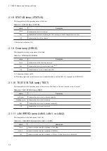
Страница 28: ... the emergency shutdown state In this state the unit cannot be started by pressing the POWER switch In such a case turn off the main power switch and then turn it on again to restore the unit 2 1 2 Reset switch RESET This switch is used to perform a hardware reset restarting the unit Do not use this switch during normal operation This switch is also used to collect a memory dump after an error occ...

Страница 29: ...ates that no error has occurred or the unit is not used Green The meaning of the lamp can be defined by the user program Red The meaning of the lamp can be defined by the user program 3rd row E3 Off Indicates that no error has occurred normal status Red Indicates that a kernel panic occurred 2nd row E2 Off Indicates that no error has occurred normal status Red Indicates that a multi bit error occu...

Страница 30: ...in a disk other than a built in SSD for example in a USB HDD 2 1 10 TEST STATUS lamp TEST This lamp indicates the operating status of the test tool This lamp is lit only when the test tool is used Table 2 5 TEST STATUS lamp TEST Lamp Description Solid green Indicates that the test tool terminated normally Blinking green Indicates that the test tool is running Red Indicates that the test tool termi...

Страница 31: ...being sent or received The blinking interval varies depending on the network traffic Off Indicates that a link has not been established 2 1 13 DisplayPort connectors DISPLAY1 and DISPLAY2 These connectors are for connecting cables from display devices 2 1 14 External Contact connector EXT This connector is used as a general purpose contact I O interface 2 1 15 USB 3 0 ports USB1 and USB2 These con...

Страница 32: ...urity slot provided on the rear of the unit is used to secure the unit by using an anti theft lock Figure 2 2 CE50 10 diagonal view Note The product does not include an anti theft lock 2 CE50 10 Names and Functions of Parts 16 ...

Страница 33: ...3 Operating the Power Supply of the CE50 10 This chapter describes operating the power supply of the CE50 10 and provides important information 17 ...

Страница 34: ... 1 1 Before turning on the power Before turning off the power see the precautions in the following 1 1 Prerequisites 1 1 1 Rated power supply 1 1 2 Installation of the unit 3 Operating the Power Supply of the CE50 10 18 ...

Страница 35: ...OWER lights red and then automatically changes to green and the unit is turned on 4 When the BIOS starts the STATUS lamp STATUS lights red When the OS has started and the unit is running the STATUS lamp STATUS changes to green Note When you turn on the power to this unit for the first time you need to log in by using the password described in 5 2 Logging in to the unit after powering it on for the...

Страница 36: ...steps in 3 2 Turning on the power to the CE50 10 At this time after turning off the power to the unit wait at least 1 minute 3 3 2 Turning off the power to the CE50 10 before turning the power on again 3 2 Turning on the power to the CE50 10 If the interval is less than 1 minute the unit might not start normally 3 3 2 Turning off the power to the CE50 10 To turn off power to the CE50 10 1 Make sur...

Страница 37: ...he main power switch MAIN POWER and contact us If you contracted maintenance services contact the maintenance personnel Using the damaged unit might cause fire or electric shock If you cannot immediately turn off the main power switch MAIN POWER because the unit is installed in a rack stop the power at the power supply source 3 Operating the Power Supply of the CE50 10 21 ...

Страница 38: ......

Страница 39: ...4 External Contact Functions This chapter describes the external contact interfaces of the CE50 10 The external contact functions cannot run without an OS 23 ...

Страница 40: ...tem Specifications Output specifications Output method Photo MOS relay contact Form B contact Load voltage Max 40 V DC external power supply required Load current Steady state Max 0 1 A point Dielectric strength 250 V AC 1 minute 4 1 4 Terminal number Table 4 2 PSDOWN terminal number Signal Terminal number PSDOWN 14 DO0_GND 2 5 15 4 1 5 Connection diagram Figure 4 1 Connection diagram 4 External C...

Страница 41: ...cations Output method Photo MOS relay contact Form A contact Rated output voltage 24 V DC external power supply Rated output current 0 1 A point Response time 10 ms or less per contact Dielectric strength 250 V AC 1 minute 4 2 4 Terminal number Table 4 4 DO terminal number Signal terminal number Signal terminal number DO_01 3 DO_06 19 DO_02 16 DO_07 7 DO_03 4 DO_08 20 DO_04 17 DO_09 9 DO_05 6 DO_1...

Страница 42: ...4 2 5 Connection diagram Figure 4 2 Connection diagram 4 External Contact Functions 26 ...

Страница 43: ...s I O Item Specifications Input specifications Input method Photocoupler contact Rated input voltage 24 V DC external power supply Rated input current 5 mA point Response time 10 ms or less per contact Dielectric strength 250 V AC 1 minute 4 3 4 Terminal number Table 4 6 DI terminal number Signal Terminal number DI_01 11 DI_02 12 DI_03 24 DI_04 25 DI_GND 10 13 23 4 3 5 Connection diagram Figure 4 ...

Страница 44: ......

Страница 45: ...figuring Software Environment This chapter describes how to configure the OS settings of the CE50 10 This chapter also describes the procedures for the development and registration of application programs 29 ...

Страница 46: ...pment environment development unit to the target unit unit to be set up The development environment and the target unit can also be consolidated into a single unit In this case there is no need to transfer the master files of application programs Figure 5 1 Configuration for constructing the environment 5 Configuring Software Environment 30 ...

Страница 47: ...sword Hitachi1 You are required to change your password immediately root enforced Changing password for edgeadm current UNIX password Enter Hitachi1 for the password New password Enter the new password Retype new password Enter the new password again for the confirmation In addition consider creating a user account for each person who operates the unit such as for each maintenance worker rather th...

Страница 48: ...en run the following command sudo systemctl start gdm3 service 3 After the command is executed the desktop login screen appears Click the user ID to be used for login 4 If the desired user is not displayed click Not listed When the following screen appears enter the user ID and then click the Next button 5 When the password entry screen appears enter the password of the user who is logging in and ...

Страница 49: ...tant note In rare cases desktop icons might overlap each other In such cases you can align the icons by right clicking a desktop area where no icons exist and then clicking Organize Desktop by Name 5 Configuring Software Environment 33 ...

Страница 50: ...er of the desktop In the menu that appears click the power icon 2 When the following dialog box appears click Restart 5 3 3 Hiding the desktop icons To hide the desktop icons 1 Click the nine point dice icon in the lower left corner of the desktop 2 The application list appears Click Terminal 5 Configuring Software Environment 34 ...

Страница 51: ...een gsettings set org gnome desktop background show desktop icons false The icons are hidden in the desktop as shown below 4 To re display the icons on the desktop run the following command on the Terminal screen 5 Configuring Software Environment 35 ...

Страница 52: ... gsettings set org gnome desktop background show desktop icons true 5 Configuring Software Environment 36 ...

Страница 53: ...ange the display resolution 1 Click the power icon in the upper right corner of the screen The system menu opens 2 Click the Setting icon in the lower left corner of the system menu The Setting screen opens 3 Select Devices and then Displays The Displays screen appears 4 Change the setting for Resolution The Apply button appears in the upper right corner of the Displays screen Figure 5 2 Displays ...

Страница 54: ...s 1 280 x 1 024 SXGA Dual displays can be set 1 920 x 1 080 FHD Dual displays can be set 1 920 x 1 200 WUXGA Dual displays can be set 3 840 x 2 160 4K UHD Only a single display can be set 5 4 2 Setting up dual displays The CE50 10 has two ports for the DisplayPort interface A dual display configuration can be created by connecting two displays to the unit Dual displays support Join Displays extend...

Страница 55: ...d in place of Display1 and Display2 4 Select Single Display and then select the display on which the screen is to be displayed Figure 5 6 Selecting Single Display 5 Click the Apply button in the upper right corner of the Displays screen A popup screen appears 5 Configuring Software Environment 39 ...

Страница 56: ...t Settings the change is not applied and the original setting is retained Note that any change made in the settings by clicking Keep Changes will be retained after the unit restarts Figure 5 8 Popup screen If you want to set the single display back to dual displays select Join Displays in the Displays screen click the Apply button and then click Keep Changes 5 Configuring Software Environment 40 ...

Страница 57: ...mple when connecting to the LAN0 port of the unit that is to be set up establish a connection to 192 168 10 1 from the development unit The following shows the contents of the network interface definition file network version 2 renderer networkd A ethernets B eth0 C addresses D 192 168 10 1 24 eth1 addresses 192 168 11 1 24 eth2 addresses 192 168 12 1 24 A Specify the service that runs at the back...

Страница 58: ... send data by using IP multicast you must create communication sockets and then specify the following settings by using a setsockopt system call 1 Set the TTL TimeToLive value Specify the number of relays for multicast data for TTL You can specify a value in the range from 0 to 255 unsigned char ipttl ipttl 5 Set the TTL value setsockopt sock IPPROTO_IP IP_MULTICAST_TTL char ipttl sizeof ipttl 2 S...

Страница 59: ... 24 D gateway4 192 168 0 254 E nameservers F search domain G addresses 192 168 0 1 H ethY dhcp4 true I A Specify the service that runs at the back end B Specify the type of LAN to be configured C Specify the device name D Specify the dot separated IPv4 address and the netmask value This definition is unnecessary if you do not use IPv4 or if you specify DHCP E Specify the IP address of the default ...

Страница 60: ...o basic information in the setting fields for the device to be specified addresses 2001 db8 1 1 20a f7ff fe15 d92b 64 L gateway6 2001 db8 1 1 21b 8bff fe79 2e4 M L Specify the IPv6 address to be individually assigned by using aaaa bbbb cccc dddd eeee ffff 1111 2222 format You can omit leading zeros in the string of numeric values separated by colons M Specify the IPv6 default gateway router addres...

Страница 61: ...nterface define the tagged VLAN interface with ID 128 B Specify the IP address 192 168 128 1 for the tagged VLAN interface 128 ethX 128 2 Apply the IP addresses Run the following command or restart the unit sudo ip_duplichk_start 5 6 2 Starting or stopping the tagged VLAN You can use the ip command to display the status of the tagged VLAN and start or stop the tagged VLAN 1 Displaying the status o...

Страница 62: ... 3 Starting the tagged VLAN The following example shows how to run the command to restart the stopped tagged VLAN sudo ip link set ethX 128 up 5 Configuring Software Environment 46 ...

Страница 63: ...d ethY which are specified as slave interfaces B Set the bonding operation mode 2 Apply the IP addresses Run the following command or restart the unit sudo ip_duplichk_start 5 7 2 Bonding operation modes Bonding has seven operation modes Select the mode appropriate for your purpose By default balance rr is selected The following table lists the operation modes Table 5 5 Bonding operation modes Ope...

Страница 64: ...Operation mode Description balance alb Load distribution is also applied to packet reception in addition to the function of balance tlb 5 Configuring Software Environment 48 ...

Страница 65: ...e systemd timesyncd service will reference B Specify the host name or IP address of the NTP server that is referenced if an attempt to synchronize with A fails C Specify the maximum permitted communication delay time communication between the NTP server and NTP client D Specify at least 16 seconds as the minimum polling interval for NTP messages E Specify the maximum polling interval for NTP messa...

Страница 66: ...ectl set timezone TIMEZONE Any time zone in the list Important note Even if you change the time zone the RTC time displayed in the BIOS menu remains in UTC If you change the time by using timedatectl the time converted to UTC is written to RTC 5 Configuring Software Environment 50 ...

Страница 67: ...tection you need to change the definition file settings Definition files Definition file for disk faults hitachi etc dskptrl_stop conf Definition file for slowdown detection hitachi etc slowdown_stop conf Item specified in a definition file stop definition value A A Specify 0 or 1 The default is 0 To change the operation change the setting to 1 Table 5 6 Definition values of the stop item Definiti...

Страница 68: ...n Personal computer PC Ethernet This device is used for the operation of data backup data restore and program update functions Connect the PC to the development unit by using an Ethernet crossover cable Figure 5 9 Configuration for connecting the PC 2 Hardware configuration No 2 A display a keyboard and a USB flash drive are connected to the unit as an HMI Table 5 8 Devices connected to the unit i...

Страница 69: ...ce operation 4 File transfer The scp command is supported for file transfer 5 Remote operation The ssh command is supported for remote operations 5 10 3 Provided files Table 5 10 Files for application development by using the unique functions of CE50 10 below shows the files provided for using the unique functions of CE50 10 Table 5 10 Files for application development by using the unique function...

Страница 70: ...v conf Development environment definition file 5 10 4 Note about SSD life The SSD installed in this unit is specified to operate for 10 years or more based on a daily amount of write data of 50 GB or less Therefore we recommend that you design the application so that the sum of the daily amount of data written by the application and the log data written by the system 50 MB day is no more than 50 G...

Страница 71: ...ns A single CE50 10 can be used as the development unit and as the construction unit In this case there is no need to transfer the master file of the application program Figure 5 11 Environment for constructing applications 5 11 2 Application program registration procedure Figure 5 12 Application installation procedure below shows the procedure for installing an application 5 Configuring Software ...

Страница 72: ...he SSD user area create a desired partition and then mount it for use Figure 5 13 Overview of the user area setting procedure below shows the procedure for specifying settings to automatically mount the user area when the OS starts Figure 5 13 Overview of the user area setting procedure 5 Configuring Software Environment 56 ...

Страница 73: ...luence of the check operation on the OS start time disable the file system check that is triggered by the elapsed time in this unit Format tune2fs c 0 i 0 device Options c 0 Specifies the number of times the file system is to be checked Specify 0 to disable the check i 0 Specifies the interval for checking the file system Specify 0 to disable the check device Specify the device name of the partiti...

Страница 74: ... as the number of sectors from the first sector use xx as the number of sectors from the end If you press the Enter key without entering anything the sector indicated by default xxxx is allocated In the following example the default is selected Last sector 2048 15728606 default 15728606 or size KMGTP 6 Enter the partition type Entering L displays a list of partition types For the Linux file system...

Страница 75: ...tor Size Code Name 1 2048 15728606 7 5 GiB 8300 Linux filesystem Note The underlined part is partition information 3 Enter q to terminate processing Command for help q b Display method 2 1 Start the gdisk command with l option and with dev sda specified for the argument The gdisk command prompt does not appear the partitions are displayed and the command terminates sudo gdisk dev sda l Disk dev sd...

Страница 76: ...matically mount the application area To automatically mount the user area when starting the unit you need to add a definition in the mount definition file hitachi etc fsconf By specifying the file definition items you can automatically reconfigure the file system by using mkfs if an attempt to repair the file system fails or automatically mount the file system if its status is normal a Definition ...

Страница 77: ...sda12 app log ext4 rw 1 2 dev sda10 app contents ext4 rw 1 0 e Checking the definition file After editing the definition file run the fsconfchk command to check the contents For details about the command see 5 18 9 fsconfchk sudo fsconfchk f Note If the file system is not constructed yet specifying a value from 1 to 3 for fsckcnt and 1 for initial causes the file system to be reformatted with the ...

Страница 78: ...ated by the start command startup check Specify how to determine whether the application program has started You can specify oneshot simple or forking Their meanings are as follows oneshot When the start command is run the application is determined to have started If RemainAfterExit is set to no the application is determined to have terminated immediately If RemainAfterExit is set to yes the appli...

Страница 79: ...check whether automatic startup is enabled sudo systemctl is enabled application name If automatic startup is enabled enabled is displayed If automatic startup is disabled disabled is displayed 5 Configuring Software Environment 63 ...

Страница 80: ...the passwd command to set the password sudo passwd New password Enter the password the entered character string is not displayed Retype new password Enter the password again the entered character string is n ot displayed passwd password updated successfully 2 Enable login with the root account The following example shows how to run the command sudo passwd u root passwd password expiry information ...

Страница 81: ...e the function again delete the hash mark The following describes how to change the settings Specify deny 10 to lock the accounts if an invalid password is entered 10 times in succession Specify unlock_time 1800 to unlock the account after 1 800 seconds You can change the settings by changing the numeric values For set values use 1 or greater half size integers 3 Setting the login timeout This fun...

Страница 82: ...te pam_pwquality so retry 3 Table 5 14 List of password condition setting options below shows the options that can be set Table 5 14 List of password condition setting options No Option Description 1 minlen Sets the password length minimum required number of characters If minlen 8 is set the password must contain at least eight characters 2 ucredit Sets the minimum number of uppercase alphabetic l...

Страница 83: ...sword for the specified number of generations and rejects the password change if the same password is used In the following example the password change is not accepted if the same password is used within three generations password policy configuration password success 1 default ignore pam_unix so obscure use_authtok try _first_pass sha512 remember 3 If the same password is entered the following me...

Страница 84: ...ports that need access from outside Disabled 2 Port transmission permission Permits transmission to the specified ports and blocks all other transmission Communication to the following ports is possible SSH 22 tcp DNS 53 udp HTTP 80 tcp HTTPS 443 tcp 3 Port reception permission limited Permits reception on the specified ports while the number of connections within a certain period is limited This ...

Страница 85: ...n permission that has been set sudo iptables D INPUT p protocol tcp udp dport port number j ACCEPT Example Specify as follows to cancel the reception permission for the HTTP server port 80 tcp sudo iptables D INPUT p tcp dport 80 j ACCEPT b Setting the port permitted for transmission 1 Run the following command to connect to a port with a given number sudo iptables A OUTPUT p protocol tcp udp dpor...

Страница 86: ...CEPT Example Specify as follows to cancel the reception permission for the HTTP server port 22 tcp sudo iptables D INPUT m state state NEW m hashlimit hashlimit htable expir e 60000 hashlimit name hasht_22 hashlimit 1 m hashlimit burst 10 p tcp dport 22 j ACCEPT d Confirming the set rules 1 Run the following command to confirm the firewall rules that have been set sudo iptables L The following sho...

Страница 87: ... sudo etc init d netfilter persistent save 5 Configuring Software Environment 71 ...

Страница 88: ...e file By default ctrl edgen is set sudo vi etc hostname After editing the file save it and then terminate processing To exit the vi command use wq write quit Then use the hostname command to apply the host name you have set sudo hostname F etc hostname 5 Configuring Software Environment 72 ...

Страница 89: ...mand ecmodeset to change the OS operation mode The following describes how to change the OS operation mode For details about the user name and password used to log in to the unit see 5 2 Logging in to the unit after powering it on for the first time For details about the commands used in each step see 5 18 Command reference 5 14 3 Changing normal mode to maintenance mode NOTICE Application program...

Страница 90: ...t and Next see the bold underlined parts sudo showecmode Current Maintenance mode Next Maintenance mode 5 14 4 Changing maintenance mode to normal mode 1 Log in to the unit login edgeadm Password 2 Check the current OS operation mode Run the showecmode command to check the current OS operation mode Confirm that Maintenance mode is displayed for both Current and Next see the bold underlined parts s...

Страница 91: ... remainder of the system which has been temporary disconnected during maintenance work 7 Turn on the power to the unit Start the unit 8 Log in to the unit login edgeadm Password 9 Check the current OS operation mode Run the showecmode command to check the current OS operation mode Confirm that Normal mode is displayed for both Current and Next see the bold underlined parts sudo showecmode Current ...

Страница 92: ...nvironment of the unit USB flash drive and CFast are available as external media In this section USB flash drive is used as the example 1 Configuration No 1 In this configuration a USB flash drive and a maintenance PC are connected to the unit Table 5 16 Devices connected to the unit in configuration No 1 Device Connection method Description Maintenance PC Ethernet This device is used for the oper...

Страница 93: ...functions To connect the maintenance PC to the unit use an Ethernet crossover cable Figure 5 17 Configuration for connecting the maintenance PC 3 Configuration No 3 In this configuration a monitor keyboard and USB flash drive are connected to the unit Table 5 18 Devices connected to the unit in configuration No 3 Device Connection method Description Keyboard USB This device is used for the operati...

Страница 94: ...e external media is connected The part added to the information shown in step 1 indicates the device name assigned to the external media In the following example sdb is the device name assigned to the external media lsblk d NAME MAJ MIN RM SIZE RO TYPE MOUNTPOINT sdb 9 0 0 16G 0 disk 4 Create a partition in the external media Run the gdisk command to create new partitions in the external media Per...

Страница 95: ...the unit a Preparation Create partitions in the external media and format them with EXT4 The backup data save area in the external media must be formatted with EXT4 Prepare external media that has free space greater than the capacity that is actually used in the directory partitions to be backed up There is no need to consider the space for unused areas in partitions because the backup file is com...

Страница 96: ... the OS operation mode is set to maintenance mode Run the showecmode command to confirm that the bold underlined parts are displayed as follows sudo showecmode Current Maintenance mode Next Maintenance mode 4 Connect the external media 5 Mount the external media on mnt ecbackup_data sudo mount external media mnt ecbackup_data 6 Run the backup command Run the ecbackup command to save the backup fil...

Страница 97: ...o umount mnt ecbackup_data 8 Log out from the unit exit To change the OS operation mode to normal mode see 5 14 4 Changing maintenance mode to normal mode 3 Backing up data in configuration No 2 The following describes the procedure for backing up data in the maintenance PC connected to the unit a Preparation Format the backup data save area of the maintenance PC with ext4 On the maintenance PC al...

Страница 98: ...n communicate with the unit ping IP address of the target unit 2 Remotely log in to the unit from the maintenance PC by using the remote operation terminal Remotely log in to the unit as a user who can run the sudo command Example user name edgeadm login edgeadm Password 3 Confirm that the OS operation mode is set to maintenance mode Run the showecmode command to confirm that the bold underlined p...

Страница 99: ...ssfully completed If the command terminates displaying a message other than Successfully completed the backup processing was interrupted due to an error Take corrective action against the error and then rerun the backup command 5 When the Please get file name Finished y message appears save the backup file in the maintenance PC by using the scp operation terminal When using Tera Term Click File an...

Страница 100: ...der the space for unused areas in partitions because the backup file is compressed before it is saved The time required to back up data is approximately 30 seconds per GB If files are to be verified additional time approximately 30 seconds is required More time might be required depending on the transfer rate of the external media Change the OS operation mode of the unit from normal mode to mainte...

Страница 101: ... to external media Partition info backup started Partition info backup finished Backup directory mnt ecbackup_data ecbackup_20210525101010 Backup destinati on Backup targets dev sda8 dev sda9 dev sda10 media etc Partition dev sda8 backup start snip Will you verify backup files y N N Whether to verify files Finished mnt ebackup_data ecbackup_20210525101010 20210525101010_sda10_01 tgz xxx xxx xxx by...

Страница 102: ...tore data from a backed up file is approximately 30 seconds per GB If files are to be verified additional time approximately 30 seconds is required More time might be required depending on the transfer rate of the external device b Operation procedure Use the maintenance PC to remotely log in to the unit in which the backup data is to be restored and then run the restoration command Figure 5 22 Fl...

Страница 103: ...the Enter key Backup directory list 1 ecbackup_20210525101010 q quit 1 Directory to be restored The progress of processing restored file name and processing time are displayed Then a message asking you whether you want to verify the restored files appears Enter y to verify the files or enter N to skip the verification Making partitions finished Restoring from extra media Restoring 20210525101010_s...

Страница 104: ...g in as a user who can run the sudo command The time required to restore data from a backed up file is approximately 30 seconds per GB If files are to be verified additional time approximately 30 seconds is required More time might be required depending on the transfer rate of the external media In addition the time for transferring backup files to the unit is required b Operation procedure Use th...

Страница 105: ...formation file YYYYMMDDhhmmss_ecbackup conf to mnt ecbackup_data by using the scp operation terminal When transfer has finished enter y and then press the Enter key The partition information is restored Please send YYYYMMDDhhmmss_ecbackup conf to mnt ecbackup_data Finished y y Enter this after scp transfer ends Making partitions finished OK 6 Send the backup file to the unit Transfer the backup fi...

Страница 106: ...tion procedure Log in to the unit to be restored and then run the restoration command Figure 5 24 Flow of restoration steps in configuration No 3 1 Log in to the unit Remotely log in to the unit as a user who can run the sudo command Example When the user name is edgeadm login edgeadm Password 2 Confirm that the OS operation mode is set to maintenance mode Run the showecmode command to confirm tha...

Страница 107: ...message If the command terminates displaying a message other than Successfully completed the restoration processing has been interrupted due to an error Take corrective action against the error and then rerun the restoration command 6 Unmount the external media from the unit After restoration finishes unmount the connected external media from the unit sudo umount mnt ecbackup_data 7 Remove the ext...

Страница 108: ...s the procedure for updating the OS of the unit with the OS file in the external media connected to the unit You can perform this operation in normal mode or maintenance mode The following describes the operation procedure in normal mode a Preparation Save the following OS files currently stored in the unit to the external media OS file osprog_base zip OS version information file OSverinfo Stop on...

Страница 109: ...t unit 2 Remotely log in to the unit from the maintenance PC Remotely log in to the unit as a user who can run the sudo command Example user name edgeadm login edgeadm Password 3 Connect the external media 4 Mount the external media on a path for example mnt osupdate sudo mount external media mnt osupdate 5 Run the version display command to check the OS versions of the active area and inactive ar...

Страница 110: ...umber is enabled dev sda2 8 Unmount the external media from the unit After restoration finishes unmount the connected external media from the unit sudo umount mnt osupdate 9 Remove the external media from the unit 10 Reboot the unit sudo reboot 11 No user operation required Automatically log out from the unit Wait for the system to start 12 Check the communication between the maintenance PC and th...

Страница 111: ...enance PC connected to the unit You can perform this operation in normal mode or maintenance mode The following describes the operation procedure in normal mode a Preparation Save the OS file currently stored in the unit to the maintenance PC Stop online application operations on the unit Stop the unit and then connect it with the maintenance PC by using an Ethernet cable If necessary disconnect o...

Страница 112: ...to the unit from the maintenance PC Remotely log in to the unit as a user who can run the sudo command Example user name edgeadm login edgeadm Password 3 Run the version display command to check the OS versions of the active area and inactive area Run the rxversion command to check the device file names and OS versions for the active area and inactive area see the bold underlined parts sudo rxvers...

Страница 113: ... containing the updated OS sudo ecosupdate mnt osupdate 6 Check the OS version and partition of the active area to be started next Run the rxosenable command with the p next startup area display option specified Then confirm that the partition to be started next has changed to the current inactive area and the OS version of that inactive area is updated see the bold underlined parts sudo rxosenabl...

Страница 114: ...TPM version information 12 Log out from the unit exit 5 Updating the OS in configuration No 3 The following describes the procedure for updating the unit OS with the OS file in the external media connected to the unit You can perform this operation in normal mode or maintenance mode The following describes the operation procedure in normal mode a Preparation Save the following OS files currently s...

Страница 115: ...t the external media 3 Mount the external media on a path for example mnt osupdate sudo mount external media mnt osupdate 4 Run the version display command to check the OS versions of the active area and inactive area Run the rxversion command to check the device file names and OS versions for the active area and inactive area see the bold underlined parts 5 Configuring Software Environment 99 ...

Страница 116: ...he unit After restoration finishes unmount the connected external media from the unit sudo umount mnt osupdate 8 Remove the external media from the unit 9 Reboot the unit sudo reboot 10 No user operation required Automatically log out from the unit Wait for the system to restart 11 Log in to the unit Log in to the unit Example user name edgeadm login edgeadm Password 12 Run the version display com...

Страница 117: ...version information 13 Log out from the unit exit 5 Configuring Software Environment 101 ...

Страница 118: ...gure 5 28 Operation states of the unit and when the hardware WDT and software WDT are active The following shows the interfaces used for operating the hardware WDT and software WDT Table 5 20 WDT operations and interfaces Classification Operation details Interface name Hardware WDT Temporarily stop and restart operation wdtctl command Display the operation status wdtstat command Forcibly restart t...

Страница 119: ...le or OFF disable TIMEOUT 15 Specify the monitoring timeout value seconds in the range from 5 to 60 PANIC ON Select ON or OFF to specify the operation to be performed if a fault is detected ON Collect a memory dump and then restart the CPU OFF Restart the CPU without collecting a memory dump CORE 4 Specify the number of cores to be monitored in the range from 1 to 4 The default reboots the unit if...

Страница 120: ...ach item see Table 5 22 Table 5 22 List of items displayed by the vmstat command Item Meaning r Number of processes that are running or that are in the executable state b Number of processes that are in an uninterruptable sleep state swpd Virtual memory size being used free Available memory size buff Memory size being used as the buffer cache Memory size being used as the cache si Size of memory t...

Страница 121: ...tion 5 18 11 eclogsave 12 rasledctl Control lighting of the RAS indicator AP lamp 5 18 12 rasledctl 13 wdtctl Enable and disable hardware WDT 5 18 13 wdtctl 14 wdtstat Check the monitoring status of hardware WDT 5 18 14 wdtstat 15 force_restart Forced restart function 5 18 15 force_restart 16 swdt_start Restart the software WDT 5 18 16 swdt_start 17 swdt_stop Temporarily stop the software WDT 5 18...

Страница 122: ...eration mode Format showecmode Description This command displays the current OS startup mode and the next OS startup mode Display format Current OS startup mode Next OS startup mode Notes If normal mode is set Normal mode is displayed If maintenance mode is set Maintenance mode is displayed If an attempt to collect information failed Unknown is displayed If Unknown is displayed a fault is likely t...

Страница 123: ... c Partition dev sda8 backup start d 31MiB 0 00 01 16 1MiB s 25 ETA 0 00 02 e Will you verify backup files y N y f Verifying 20210525101010_sda8_01 gz f The file and the partition doesn t match Retry y N y g 31MiB 0 00 01 16 1MiB s 25 ETA 0 00 02 e Will you verify backup files y N y f Verifying 20210525101010_sda8_01 gz f Finished 20210525101010_sda8_01 gz xxx xxx xxx bytes h snip Directory media ...

Страница 124: ...01010_sda8_01 gz This message asks you whether you want to verify that the backup files are saved normally If you enter y the saved backup file is compared with the target partition or directory to confirm that they match If you enter N the message in h appears and then creation of the next backup file starts g The file and the partition doesn t match Retry y N y If the verification in f shows tha...

Страница 125: ...ntenance PC by using the scp command After transferring the file enter y and then press the Enter key Then the file indicated by file name is deleted and saving of the next backup file starts If you press the Enter key without entering anything or enter a character other than y the same message appears again and the system waits for you to enter information again 4 Enter q and then press the Enter...

Страница 126: ...ing press the N key 6 Backup aborted Backup was canceled by a user operation None 5 18 4 ecrestore Name ecrestore Restore backup data Format ecrestore Description This command restores backup data When you run the command the system waits for you to enter information Perform restoration according to the menu Options No options need to be specified Any specified options are ignored Display example ...

Страница 127: ...displayed Specifically the number of bytes from the beginning of the partition to the restoration start point is indicated for start and the size to be restored unit bytes is indicated for size d 31MiB 0 00 01 16 1MiB s 25 ETA 0 00 02 The progress of restoration of the backup file The following are displayed from the left to right Extended capacity Elapsed time Data transfer rate amount of transfe...

Страница 128: ...ly completed h Table 5 29 Description of the screen after restoration from the maintenance PC started Item Display Description a to h See Table 5 28 Description of the screen after restoration from external media started See Table 5 28 Description of the screen after restoration from external media started i Restoring from maintenance PC This message indicates that restoration from the maintenance...

Страница 129: ...ed for restoration Connect the correct external media and then rerun the command 5 18 5 ecosupdate Name ecosupdate Update the OS in the inactive area Format ecosupdate h directory name Description This command updates the OS in the inactive area of the unit with the OS update file in the specified directory After the unit restarts the inactive area with the updated OS is restarted as the active ar...

Страница 130: ... the file again and then rerun the command 7 ecosupdate Failed to save hitachi etc ecosupdate system 1 2 boot tgz An attempt to save the boot partition file failed Confirm that hitachi etc ecosupdate is writable and then rerun the command 8 ecosupdate Failed to save root partition to dev sda 2 3 An attempt to save the root partition failed Rerun the command 9 Backup for boot partition failed An at...

Страница 131: ... sudo rxosenable help usage rxosenable h p s e 2 3 optional arguments h help show this help message and exit p print Print enabled OS version default s switch Switch the active partition e 2 3 enable 2 3 Enable the partition 2 3 Diagnosis For the exit code 0 is returned if the status is normal and 1 is returned if an error is detected Table 5 32 List of rxosenable command error messages below show...

Страница 132: ...ormat Options nodate Omit the display of the date parts 8 and 11 below Display format Figure 5 29 rxversion display format Display items Table 5 33 List of items displayed by rxversion below shows the display items Table 5 33 List of items displayed by rxversion No Display 1 Active area partition 2 Inactive area partition 3 Program product name 4 Program product model 5 OS version 6 OS revision 7 ...

Страница 133: ... shown in the display format fails is output 5 18 8 disklchk Name disklchk Diagnose the SSD life Format disklchk Description This command analyzes the write count information managed within the SATA connected SSD and displays the SSD life as a percentage in the following format The value used to calculate the percentage is also displayed for each item Display format referenced item name YY YY Valu...

Страница 134: ...ame Specify the path of the file you want to check If the file name is specified by the option the command checks the contents of that file Diagnosis For the exit code 0 is returned if the status is normal and 1 is returned if an error is detected Table 5 36 List of fsconfchk command error messages below shows error messages that are output when an error is detected Table 5 36 List of fsconfchk co...

Страница 135: ...nt message 3 showkxmessage grep error An error occurred during message extraction Display example The following shows an example of when all KX messages are displayed by the command with no option specified sudo showkxmessage syslog 1 7 May 15 12 03 41 ec kernel 25 131888 KXDL001 E Ethernet adapter eth 2 carrier lost syslog 1 615 May 15 12 04 47 ec kernel 25 686804 KXDL001 E Ethernet adapter e th1...

Страница 136: ...s Options No option specified All log data of the log type specified by the d option are collected d logtype Log data of the log type specified for logtype is saved To specify multiple log types separate each type by a comma You can specify the following values for logtype 1 System log collection target files compressed to tgz format are collected 2 Memory dump data in the memory dump area to tgz ...

Страница 137: ...userlog tgz 5_MAINT_INFO maint_info tgz Execution example The following example shows how to run the command when a formatted USB external media is connected to the unit and is recognized as dev sdb1 sudo mkdir tmp logdir sudo mount dev sdb1 tmp logdir sudo eclogsave d 4 tmp logdir 5 18 12 rasledctl Name rasledctl Control lighting of the RAS indicator AP lamp Format rasledctl Description This comm...

Страница 138: ...ges below shows error messages that are output when an error is detected Table 5 39 List of wdtctl command error messages No Error message Description 1 usage wdtctl s r No option is specified or the specified option is invalid 2 wdtctl device is not found The driver for hardware WDT has not started or the device file for accessing the driver cannot be opened 3 wdtctl not a super user The command ...

Страница 139: ...is detected Table 5 41 List of force_restart command error messages No Error message Description 1 force_restart device is not found The driver for the hardware WDT has not started or the device file for accessing the driver cannot be opened 2 force_restart not a super user The command is not run with root privileges 5 18 16 swdt_start Name swdt_start Restart the software WDT Format swdt_start Des...

Страница 140: ...eration of the software WDT follows the definition of the INLOOP symbol in the hitachi etc swdt conf file Diagnosis For the exit code 0 is returned if the status is normal and 1 is returned if an error is detected Table 5 43 List of swdt_stop command error messages below shows error messages that are output when an error is detected Table 5 43 List of swdt_stop command error messages No Error mess...

Страница 141: ...tions p port Displays the connection state connected or disconnected of the USB device for the specified USB port If the device is connected Connect appears If the device is disconnected Disconnect appears For port specify the USB port number 1 or 2 on which you want to perform operations To perform operations for all ports or check their states at the same time specify all 1 Perform operations on...

Страница 142: ...mple shows that the device is disconnected from port 2 sudo usbctl p 2 Port 2 Disconnect The following example shows how to run the command to check the states of all USB ports This example shows that devices are connected to all ports sudo usbctl p all Port 1 Connect Port 2 Connect c option The following example shows how to run the command to connect a device to USB port number 1 sudo usbctl p 1...

Страница 143: ...6 Managing User Accounts This chapter describes how to add and delete user accounts for the CE50 10 127 ...

Страница 144: ... a password that conforms to the policies For details about the password policies see 5 12 2 Setting password policies New password Enter the password Retype new password Enter the password again for confirmation 3 Check the output message When the user account has been added successfully the following message appears passwd password updated successfully 6 Managing User Accounts 128 ...

Страница 145: ...6 2 Deleting a user account This operation uses the sudo command To delete a user account specify the user name and then run the userdel command sudo userdel r user name 6 Managing User Accounts 129 ...

Страница 146: ... password according to the output messages passwd Changing password for current login user name current UNIX password Enter the current password New password Enter the new password Retype new password Enter the new password again for confirmation 4 Check the output message When the password has changed successfully the following message appears passwd password updated successfully 6 Managing User ...

Страница 147: ...xample shows that the privilege for sudo command execution has been granted to the user named myuser uid 1002 myuser gid 1002 myuser groups 1002 myuser 27 sudo 6 4 2 Adding the privilege for sudo command execution This operation uses the sudo command Run the gpasswd command with the user name specified sudo gpasswd a user name sudo 6 4 3 Deleting the privilege for sudo command execution This opera...

Страница 148: ......

Страница 149: ...7 Maintaining the CE50 10 This chapter describes maintenance of the CE50 10 133 ...

Страница 150: ...er menu from the low order menu and Used to select a menu or a menu group displayed at the top of the screen and Used to select an item in a menu or menu group and Used to select a value to be set Values that can be set vary depending on the items selected by the key operation Use the and keys on the numeric keypad because Japanese characters cannot be entered in the system BIOS screen Space Used ...

Страница 151: ... Version Automatically recognized TXE Version Automatically recognized Advanced EIST Disabled Do not change the settings Turbo Boost Disabled USB Legacy Enabled After AC Power On Power On Specify the processing to be performed when the power to the unit is turned on Power On The OS automatically starts when the power is turned on Stay Off The OS enters software power off mode when the power is tur...

Страница 152: ...as saved in ROM the last time Load Setup Defaults Click this item to read the BIO default settings This only reads the defaults without saving them to ROM To save the settings to ROM use Exit Saving Changes 1 The date and time are applied to the RTC real time clock as soon as they are changed 2 The CPU frequency and TDP are changed depending on the CPU operation mode CPU Frequency as shown below T...

Страница 153: ...alue 5 Open Exit in the high order menu again Position the cursor to Exit Saving Changes and then press the Enter key The following message appears Save configuration changes and exit now 6 Select Yes and then press the Enter key This is the end of the operation 7 Maintaining the CE50 10 137 ...

Страница 154: ... wipe the display Also remove any dust or dirt adhering to the heat sink of the unit Checking for abnormal temperature or humidity and abnormal noise Once a day Make sure that the ambient temperature and humidity around the unit are within the range of ambient temperature and humidity shown in A 2 Operating environmental conditions Also make sure that no abnormal noise is generated from the unit C...

Страница 155: ...to excessive vibration or physical impact resulting in failure of the unit Select or design a cubicle or rack that meets the installation conditions Similarly make sure that the unit is not subject to vibration or physical impact when you move carry or transport it Table 7 5 Periodic inspection items shows periodic inspection items Hitachi is responsible for performing periodic inspection under ma...

Страница 156: ... repair or for any other reason the new unit or part might be of a different model with compatible functions For peripheral devices refer to the user s guide that comes with each device for the necessary information about maintenance We have confirmed that zinc oxide whiskers could negatively affect devices Do not use electrogalvanized materials in the place where this unit and peripheral devices ...

Страница 157: ...8 Troubleshooting This chapter describes troubleshooting of the CE50 10 141 ...

Страница 158: ...8 1 Troubleshooting flow chart Figure 8 1 Front view of the unit The following shows the troubleshooting flow chart 8 Troubleshooting 142 ...

Страница 159: ...Figure 8 2 Troubleshooting flow chart 8 1 1 Smoke or unusual odor WARNING 8 Troubleshooting 143 ...

Страница 160: ...re might have occurred Please contact us 8 1 5 STATUS lamp STATUS is lit red after the power is turned on A fault might have occurred during BIOS initialization or OS startup Please contact us 8 1 6 RAS indicator E1 E2 or E3 is lit red after the power is turned on A fault has been detected in the unit Please contact us The following shows the lamp indications and their respective error description...

Страница 161: ...e network settings see 5 Configuring Software Environment 2 Unplug the LAN cable and then insert it firmly 3 Confirm that the LAN cable is connected to the correct port 4 Replace the LAN cable 5 If you are using network equipment take the following actions Confirm that the power to the network equipment is turned on Turn on the power to the network equipment and then turn on the power to the unit ...

Страница 162: ...8 1 14 Cannot turn off the power to the unit Please contact us 8 Troubleshooting 146 ...

Страница 163: ...nance information in configuration No 3 8 2 1 Collecting maintenance information in configuration No 1 Use a maintenance PC to save maintenance information in external media connected to the unit Before you start this operation perform the following Disconnect the unit from the external system Stop the unit and then connect it to the maintenance PC by using an Ethernet cable Create partitions in t...

Страница 164: ... eclog 1_RAS_LOG raslog tgz completed 20150801181021 eclog 2_MEM_DUMP 20150718212439 tgz completed 20150801181021 eclog 3_SDA6_LOG sda6 tgz completed 20150801181021 eclog 4_USER_LOG userlog tgz completed 20150801181021 eclog 5_MAINT_INFO maint_info tgz completed 20150801181021 eclog 6_EXTPP_LOG extpplog tgz completed Started a compression of system information Successfully completed 20150801181021...

Страница 165: ...t the OS operation mode is set to maintenance mode Run the showecmode command to confirm that the bold underlined parts are displayed as follows sudo showecmode Current Maintenance mode Next Maintenance mode 4 Run the batch collection command Run the eclogsave command to save maintenance information in external media The following shows an example in which maintenance information is saved in the t...

Страница 166: ... maintenance PC is the same as the file at the acquisition source check the bold underlined parts If the maintenance PC is Linux ls l 20150801181021 eclog list rw r r 1 root root 873 Aug 1 18 10 20150801181021 eclog list ls l 20150801181021 eclog tgz rw r r 1 root root 115753706 Aug 1 18 10 20150801181021 eclog tgz If the maintenance PC is Windows dir directory under W Users hoge eclogsave_dir 201...

Страница 167: ...nd to save maintenance information in the external media The following shows an example in which the external media is recognized as dev sdb and batch collected information is stored in dev sdb1 sudo eclogsave dev sdb1 Started a save of system information 20150801181021 eclog 1_RAS_LOG raslog tgz completed 20150801181021 eclog 2_MEM_DUMP 20150718212439 tgz completed 20150801181021 eclog 3_SDA6_LOG...

Страница 168: ...Start the target unit by turning on the power For details about how to change the OS operation mode to normal mode see 5 14 4 Changing maintenance mode to normal mode 8 Troubleshooting 152 ...

Страница 169: ...e the unit specifications external interface real time clock specifications connector specifications error messages option functions for application programs library interface reference security specifications and communication sheet 153 ...

Страница 170: ...ake on LAN Serial Not supported External contact EXT D Sub25 pin when an EXT board is mounted DI General purpose input signals Photocoupler contact x 4 DO General purpose output signals Photo MOS relay contact form A x 10 PSDOWN Power supply down signals Photo MOS relay contact form B x 1 External dimension width x depth x height 210 x 285 x 69mm excluding the height of the rubber feet 1 The resol...

Страница 171: ...cy mode Low Frequency mode CPU frequency 5 1 6 GHz 1 3 GHz TDP 5 12 W 7 W External equipment connection Unmentioned USB equipment is not used excluding a mouse and keyboard or USB self power equipment is used Load ratio Unmentioned CPU usage ratio Average 70 or less 6 5 The CPU frequency and TDP CPU s allowable thermal design power change depending on the operation mode which is set to Normal Freq...

Страница 172: ...nit is turned off some components such as the clock operates by battery backup If the unit is stored in an environment outside the temperature range of guaranteed operation you might have to reset the BIOS settings such as the time when re using the unit If you need to reset the BIOS settings contact us Note 2 The unit cannot be used in an environment where conductive dust is present in the air Th...

Страница 173: ...ation 1 H01 S Standard specification Memory 4 GB without an external connection Without frame fixing brackets 2 HE2 S Standard specification Memory 8 GB with an external connection 3 H02 SA Standard specification Memory 8 GB without an external connection 4 HE2 SA Standard specification Memory 8 GB with an external connection 5 H01 U Model without an OS Memory 4 GB without an external connection W...

Страница 174: ...ory 5e or higher External contact input output interface 30 m Use a shielded cable DisplayPort interface For details on usable cables see Remarks Recommended to use a cable attached with a display B 2 Current specifications for the USB 3 0 port and DisplayPort The maximum current for each port of the unit is as follows Table B 2 Maximum current for port Interface name Voltage Maximum current USB 3...

Страница 175: ...backup battery while the power is off Table C 1 Real time clock specifications Item Specification Clock function Hour minute second 24 hour system Date function Year month day Time accuracy Plus minus 9 seconds per day or less Battery backup Lithium battery Reference value when the ambient temperature is 25 degrees Celsius C Real time Clock Specifications 159 ...

Страница 176: ... 0 1 USB3 0 2 ports Figure D 1 USB 3 0 pin assignment Table D 1 USB 3 0 signal names Pin number Signal name Pin number Signal name U1 5V L1 5V U2 USBD0 L2 USBD0 U3 USBD0 L3 USBD0 U4 GND L4 GND U5 SSRX0 L5 SSRX0 U6 SSRX0 L6 SSRX0 U7 GND L7 GND U8 SSTX L8 SSTX U9 SSTX L9 SSTX D 2 LAN RJ 45 8 pin connector Figure D 2 LAN RJ 45 pin assignment Table D 2 LAN RJ 45 signal names Pin number Signal name Pin...

Страница 177: ... GND 2 GND 12 Lane3 3 Lane0 13 Config1 4 Lane1 14 Config2 5 GND 15 AUX 6 Lane1 16 GND 7 Lane2 17 AUX 8 GND 18 HPD 9 Lane2 19 GND 10 Lane3 20 POW D 4 External contact EXT connector D sub25 pin inch screw thread male connector Figure D 4 External contact EXT pin assignment Table D 4 External contact EXT signal names Pin number Signal name Pin number Signal name 1 Reserved 14 PSDOWN 2 DO0_GND 1 15 DO...

Страница 178: ...6 DO_05 19 DO_06 7 DO_07 20 DO_08 8 DO1_GND 2 21 DO1_GND 2 9 DO_09 22 DO_10 10 DI_GND 23 DI_GND 11 DI_01 24 DI_03 12 DI_02 25 DI_04 13 DI_GND Note 1 DO0_GND is the return signal for PSDOWN and for DO_01 through DO_05 Note 2 DO1_GND is the return signal for DO_06 through DO_10 D Connector Specifications 162 ...

Страница 179: ...ber Z Function number LAN controller error KXBT011 W PCI device check failed Bus X Device Y Func Z X Bus number Y Device number Z Function number PCI device error other than LAN KXBT030 E Core check failed core N N Number of detected cores Abnormal number of cores KXBT040 E Physical memory check failed DRAM X X Installed memory capacity KB Main memory capacity error KXBT020 I GPIO data is as follo...

Страница 180: ...verity Uncorrected Fatal ethX Interface name Bus error A PCI bus error was detected in the unit A unit failure might have occurred Replace the unit KXDL005 E Ethernet adapter ethX initial error ethX Interface name Initialization error An attempt to initialize the LAN controller failed Replace the unit because the LAN controller is faulty KXDL006 E Ethernet adapter ethX transmit timeout error ethX ...

Страница 181: ...e shortage error messages Message ID Message Cause meaning Action KXKL101 W There is not enough free memory X 1 KB limit Y 2 KB free The memory capacity is insufficient free space is less than 20 Use the showmem command to identify which process uses a lot of memory KXKL102 E Insufficient memory free size Y 2 KB The memory capacity is insufficient free space is less than 10 KXKL301 E Insufficient ...

Страница 182: ... 4 KXDO004 W DO hold mode change failed An attempt to change DO hold mode failed 3 4 KXIO001 E IO board cable disconnected The I O board cable is disconnected during online 1 Whether the previous output value is retained or the current value is output depends on the timing at which an error occurred 2 An attempt to write output data failed for all DO channels that is the previous value is retained...

Страница 183: ... mount the partition as the area for use by Docker and then load the image file for the container 1 Initializing Docker To use Docker you need to mount the Docker partition in the operation environment For details about how to create partitions see 2 Creating partitions To start an Ubuntu 18 04 3 image at least 150 MB free space is required for a partition More free space is required according to ...

Страница 184: ...ding has been performed normally the following should be displayed REPOSITORY TAG IMAGE ID CREATED SIZE ubuntu 18 04 a2a15febcdf3 5 days ago 64 2MB This concludes the loading of Docker images to the operation environment 4 Confirming that the container has started The following describes how to start a container from a Docker image and then terminate that container The following example describe h...

Страница 185: ...e program Enter in command examples indicates pressing of the Enter key on the keyboard 1 Copy the sample program to any directory cp usr share open62541 examples tutorial_server_variable c client c 2 Compile the sample program gcc client c lopen62541 o client gcc tutorial_server_variable c lopen62541 o server 3 Run the sample program server client When OPC UA communication is successful the follo...

Страница 186: ...ails about include files and libraries that are to be specified when compiling the program see Table 5 10 Files for application development by using the unique functions of CE50 10 2 Reference a Format include rasif h int rasledctl int cmd b Description You can control lighting of the RAS indicator AP lamp by issuing this library interface with an argument added c Arguments USER_GREEN Turn on the ...

Страница 187: ...ccesses all DI or DO channels by a single call Four DI channels or ten DO channels can be accessed The standard access time for DI or DO is approximately 5 milliseconds or less in a normal state If DI or DO does not return a response for 10 milliseconds a timeout is detected and the processing terminates abnormally At this time the error code ETIMEDOUT is returned c Arguments board Specify the acc...

Страница 188: ...ister Message KXDO002 W KXDO003 W or KXDO004 W is output ETIMEDOUT A timeout was detected during access to DI or DO A message KXDI001 W or KXDO001 W is output e Notes For the value specified for the buf argument whether NULL is specified is checked but whether the specified area is accessible is not checked Therefore you must allocate the data storage area and specify the address of that area If t...

Страница 189: ...hat are to be specified when compiling the program see Table 5 10 Files for application development by using the unique functions of CE50 10 2 Reference a Format include rasif h int force_restart void b Description Issuing this function without an argument forcibly resets and restarts the CPU within approximately 20 to 60 seconds c Return values 0 Normal termination 1 Abnormal termination The foll...

Страница 190: ... for the port argument USB_ENABLE Connect the device for the USB port number specified for the port argument USB_STAT Obtain the connection and disconnection states for all USB port numbers ignoring the value of the port argument port Specify the USB port number 1 or 2 To perform operation for all ports at the same time specify a negative value Note Macro that determines the connection state Speci...

Страница 191: ...codes is returned for the error number errno EINVAL The argument has an error ENXIO The driver for monitoring the hardware watchdog timer has not started or the device file for accessing the driver cannot be opened ENOENT A device file for the GPIO driver does not exist EIO A hardware access error occurred G Library Interface Reference 175 ...

Страница 192: ...file name Description Retention period standard Prerequisite 1 syslog System message Approx 3 days The unit is restarted once a day 2 wtmp Login history Approx 160 days A login to the unit is performed once a day 3 auth log Authentication history Approx 13 days Operation with root privileges is performed approximately 20 times per day 4 sar log Operation management information Approx 3 days 5 netl...

Страница 193: ... normal mode 3 Copy the package files Use the following command to create the directory where the package files are to be placed mkdir tmp opessl_update Copy all the package files from the external media or maintenance PC to the directory you created 4 Run the following command sudo apt y install tmp openssl_update deb This ends the procedure for updating the encryption algorithm H Security Specif...

Страница 194: ...l_sys platform cs_edge Enter your inquiries about this product on our website You will then be contacted by the appropriate department Table I 1 Data sheet No Item Status 1 Lamp status POWER lamp POWER Green red off STATUS lamp STATUS Green red off DRIVE lamp DRIVE Green green blinking red off TEST STATUS lamp TEST Green red off RAS indicator AP Green red off E3 Red off E2 Red off E1 Red off 2 Ind...

Отзывы: