background image

2–16

Hardware description

Hitachi Unified Storage Hardware Service Guide

Rear panel

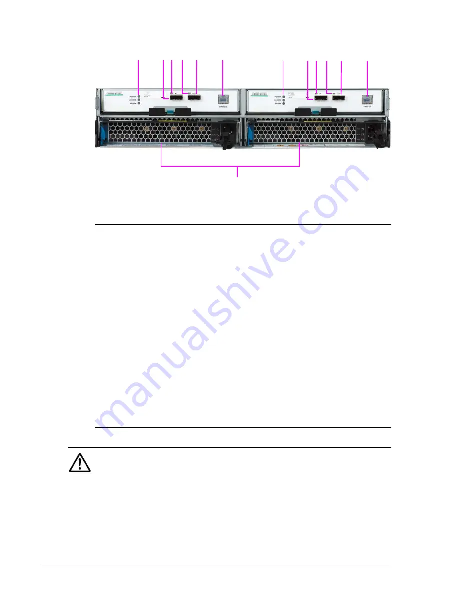
Figure 2-19:  DBS rear panel

Legend:

POWER, LOCATE, ALARM LEDs
See 

I/O Module (ENC), DBS, DBSD, DBL, and DBLD Drive Boxes on page 2-

42

.

?

IN Port
Connects to a CBSS, CBSL, CBL, or CBLD Controller Box or a DBS, DBL, 
DBX, or DBF Drive Box.

?

IN Port LED
ON when IN port is connected to a CBSS, CBSL, CBL, CBLD, DBS, DBSD, 
DBL, DBLD, DBX, or DBF.

?

Out Port LED
See 

I/O Module (ENC), DBS, DBSD, DBL, and DBLD Drive Boxes on page 2-

42

.

?

OUT Port
See 

I/O Module (ENC), DBS, DBSD, DBL, and DBLD Drive Boxes on page 2-

42

.

?

Console Port
Not used.

?

Power Unit
See 

Power Unit for CBXSS, CBXSL, CBSS, and CBSL Controller Boxes on 

page 2-45

 an

Power Unit for DBSD/DBLD Drive Box on page 2-46

.

?? ?

?

?

?

?? ?

?

?

NOTE: The DBSD rear panel is identical to the figure above, except the AC 

receptacles are replaced by receptacles for accommodating DC power.

Содержание CBL

Страница 1: ...Changes in this revision Document organization Contents FASTFIND LINKS MK 91DF8302 16 Hitachi Unified Storage Hardware Service Guide ...

Страница 2: ...nder the terms and conditions of Hitachi Data Systems applicable agreements All of the features described in this document may not be currently available Refer to the most recent product announcement or contact your local Hitachi Data Systems sales office for information on feature and product availability Notice Hitachi Data Systems products and services can be ordered only under the terms and co...

Страница 3: ... a serious accident Notice of export controls Export of technical data contained in this document may require an export license from the United States government and or the government of Japan Contact the Hitachi Legal Department for any export compliance questions China RoHS The indication is given based on the Requirements for Controlling Pollution Caused by Electronic Information Products Regul...

Страница 4: ...BDE CBXSS CBXSL CBSS CBSL CBL CBLE CBLD x o o o o o DBS DBSD DBL DBLD DBF DBX x o o o o o DBW x o o o o o x this toxic or hazardous substances contained in all of the homogeneous materials for this part is below this limit requirement in SJ T 11363 2006 o this toxic or hazardous substances contained in at least one of the homogeneous materials used for this part is above the limit requirement in S...

Страница 5: ...ronic equipment should be disposed at the end of life separately from your household wastes There are separate collection systems for recycling in EU For more information contact the local authority or the dealer where you purchased the product Recycling A Nickel hydride battery is used as a battery in the Cache Backup Battery A Nickel hydride battery is a resource that is can be recycled When you...

Страница 6: ...software developed under OpenSSL License and Original SSLeay License OpenSSL License and Original SSLeay License are as follows Licenses The OpenSSL toolkit stays under a dual license i e both the conditions of the OpenSSL License and the original SSLeay license apply to the toolkit See below for the actual license texts Actually both licenses are BSD style Open Source licenses In case of any lice...

Страница 7: ...IMPLIED WARRANTIES OF MERCHANTABILITY AND FITNESS FOR A PARTICULAR PURPOSE ARE DISCLAIMED IN NO EVENT SHALL THE OpenSSL PROJECT OR ITS CONTRIBUTORS BE LIABLE FOR ANY DIRECT INDIRECT INCIDENTAL SPECIAL EXEMPLARY OR CONSEQUENTIAL DAMAGES INCLUDING BUT NOT LIMITED TO PROCUREMENT OF SUBSTITUTE GOODS OR SERVICES LOSS OF USE DATA OR PROFITS OR BUSINESS INTERRUPTION HOWEVER CAUSED AND ON ANY THEORY OF LI...

Страница 8: ...g acknowledgement This product includes cryptographic software written by Eric Young eay cryptsoft com The word cryptographic can be left out if the routines from the library being used are not cryptographic related 4 If you include any Windows specific code or a derivative thereof from the apps directory application code you must include an acknowledgement This product includes software written b...

Страница 9: ... THE REGENTS AND CONTRIBUTORS AS IS AND ANY EXPRESS OR IMPLIED WARRANTIES INCLUDING BUT NOT LIMITED TO THE IMPLIED WARRANTIES OF MERCHANTABILITY AND FITNESS FOR A PARTICULAR PURPOSE ARE DISCLAIMED IN NO EVENT SHALL THE REGENTS OR CONTRIBUTORS BE LIABLE FOR ANY DIRECT INDIRECT INCIDENTAL SPECIAL EXEMPLARY OR CONSEQUENTIAL DAMAGES INCLUDING BUT NOT LIMITED TO PROCUREMENT OF SUBSTITUTE GOODS OR SERVI...

Страница 10: ...erference in which case the user will be required to correct the interference at his own expense Testing was done with shielded cables Therefore in order to comply with the FCC regulations you must use shielded cables with you installation The EMI test was done in the following configuration If trouble occurs in another configuration a user may be requested to take appropriate preventive measures ...

Страница 11: ...nal Commission on Rules for the Approval of Electrical Equipment 5 BS British Standard Institution 6 AS Standards Association of Australia Warning labels on equipment Warning labels are pasted on portions of the equipment where special care is required These warnings are for service personnel not customers The following table describes the symbols shown in warning labels Label Description Do not d...

Страница 12: ...xii Hitachi Unified Storage Hardware Service Guide Serial Numbers Hitachi Unified Storage Models 110 and 130 ...

Страница 13: ...xiii Hitachi Unified Storage Hardware Service Guide Labels on the CBXSS Either a or b is affixed ...

Страница 14: ...xiv Hitachi Unified Storage Hardware Service Guide Labels on the CBXSL Either a or b is affixed a b ...

Страница 15: ...xv Hitachi Unified Storage Hardware Service Guide Labels on the CBSS Either a or b is affixed a b ...

Страница 16: ...xvi Hitachi Unified Storage Hardware Service Guide Labels on the CBSL Either a or b is affixed a b ...

Страница 17: ...xvii Hitachi Unified Storage Hardware Service Guide Labels on the CBL CBLE CBLD Either a or b is affixed a b ...

Страница 18: ...xviii Hitachi Unified Storage Hardware Service Guide Labels on the DBS DBSD Either a or b is affixed a b ...

Страница 19: ...xix Hitachi Unified Storage Hardware Service Guide Labels on the DBL DBLD Either a or b is affixed a b ...

Страница 20: ...xx Hitachi Unified Storage Hardware Service Guide Labels on the CBXSS ...

Страница 21: ...xxi Hitachi Unified Storage Hardware Service Guide Labels on the DBF Either a or b is affixed a b ...

Страница 22: ...xxii Hitachi Unified Storage Hardware Service Guide Labels on the DBX Either a or b is affixed kg a b a b ...

Страница 23: ...xxiii Hitachi Unified Storage Hardware Service Guide Labels on front of the DBW added on April 2014 ...

Страница 24: ...xxiv Hitachi Unified Storage Hardware Service Guide Labels on front of the DBW effective until end of March 2014 ...

Страница 25: ...xxv Hitachi Unified Storage Hardware Service Guide Labels on rear of the DBW added on April 2014 ...

Страница 26: ...xxvi Hitachi Unified Storage Hardware Service Guide Labels on rear of the DBW effective until end of March 2014 Label position and contents on DBW rail OR ...

Страница 27: ...xxvii Hitachi Unified Storage Hardware Service Guide Labels on the drives CBXSS CBSS DBS DBSD CBXSL CBSL DBL DBLD DB Z DBF ...

Страница 28: ...xxviii Hitachi Unified Storage Hardware Service Guide DBX DBW Labels on cache backup battery CBL CBLE CBLD ...

Страница 29: ...xxix Hitachi Unified Storage Hardware Service Guide Labels on fan module CBL CBLE CBLD Labels on DBW Labels on the power unit CBXSS CBXSL CBSS CBSL ...

Страница 30: ...xxx Hitachi Unified Storage Hardware Service Guide CBL CBLE CBLD DBS DBSD DBL DBLD DBF ...

Страница 31: ...xxxi Hitachi Unified Storage Hardware Service Guide DBX DBW Positions and contents of labels on DBW side card Positions and Contents of Labels on DBW rail ...

Страница 32: ...xxxii Hitachi Unified Storage Hardware Service Guide Labels on the controller CBXSS CBXSL CBSS CBSL CBL CBLE CBLD ...

Страница 33: ...xxxiii Hitachi Unified Storage Hardware Service Guide Labels on Host I O Boards CBSS CBSL Host I O Board Fibre Channel Labels on Host I O Boards CBXSS CBXSL CBSS CBSL 1 Gbps iSCSI 10 Gb iSCSI ...

Страница 34: ...xxxiv Hitachi Unified Storage Hardware Service Guide Labels on Host I O Module CBL CBLE CBLD Fibre Channel iSCSI Labels on Drive I O Module CBL CBLE CBLD ...

Страница 35: ...xxxv Hitachi Unified Storage Hardware Service Guide Labels on Management Module CBL CBLE CBLD LAN UPS ...

Страница 36: ...xxxvi Hitachi Unified Storage Hardware Service Guide Labels on I O Module ENC DBS DBSD DBL DBLD DBF ...

Страница 37: ...xxxvii Hitachi Unified Storage Hardware Service Guide DBW Labels on I O Card ENC DBX Labels on Host Connector ...

Страница 38: ...xxxviii Hitachi Unified Storage Hardware Service Guide Labels on SAS ENC Cable Labels on cable holder DBX In ...

Страница 39: ...xxxix Hitachi Unified Storage Hardware Service Guide Out ...

Страница 40: ...xl Hitachi Unified Storage Hardware Service Guide ...

Страница 41: ... Verifying component failures 1 1 Replaceable parts 1 2 Identifying hardware faults 1 3 Using Storage Navigator Modular 2 to identify failures 1 3 2 Hardware description 2 1 Matching Controller Boxes and Drive Boxes 2 2 Storage system dimensions 2 3 Controller Boxes at a glance 2 4 CBXSS Controller Box DF850 CBSSR 2 5 Front panel bezel 2 5 Front panel without bezel 2 5 Rear panel 2 6 CBXSL Control...

Страница 42: ... DBL DBLD Drive Box 2 17 Front panel bezel 2 17 Front panel without bezel 2 17 Rear panel 2 18 DBF Drive Box 2 19 Front panel bezel 2 19 Front panel without bezel 2 19 Rear panel 2 20 DBX Drive Box 2 21 Front panel bezel 2 21 Rear panel 2 22 Top view 2 23 DBW Drive Box 2 24 Front panel bezel 2 24 Rear panel 2 25 Top view 2 25 Hardware descriptions 2 26 LED definitions 2 26 Front panel LEDs 2 26 Dr...

Страница 43: ...2 48 Rear panel of CBL CBLD Controller Box 2 51 Management Module for CBL CBLD Controller Box 2 53 Drive I O Module for CBL CBLD Controller Box 2 54 Host I O Modules for CBLCBLD Controller Box 2 55 DBW Drive Box 2 57 I O Module ENC for DBW Drive Box 2 57 Power Unit for DBW Drive Box 2 58 DBW Drive Box drawer 2 59 DBW Fan Module 2 60 3 Procedures before and after replacing components 3 1 Electrosta...

Страница 44: ...wer Unit 5 4 Replacing the cache backup battery on a CBL Controller Box 5 6 Removing the cache battery backup 5 6 Installing the new cache backup battery 5 6 6 Replacing a Fan Module 6 1 Precautions when replacing the Fan Module 6 2 Replacing the Fan Module on a CBL Controller Box 6 2 7 Replacing a Power Unit 7 1 Precautions when replacing the Power Unit 7 2 Replacing the Power Unit on CBXSS CBXSL...

Страница 45: ...roller Boxes 10 3 Replacing a Host I O Module on a CBL Controller Box 10 5 11 Replacing the Host connector 11 1 Precautions when replacing a Host Connector 11 2 Replacing the Host Connector 11 2 12 Replacing the Drive I O Module 12 1 Precautions when replacing the Drive I O Module 12 2 Replacing the Drive I O Module on a CBL Controller Box 12 2 13 Replacing the I O Module ENC 13 1 Precautions when...

Страница 46: ...ling firmware on the Hitachi Unified Storage 150 15 32 Changing the number of Drive I O Modules 15 34 Configuring the storage system serial number 15 36 Registering the Hitachi Unified Storage 150 15 38 Completing the upgrade 15 38 16 General maintenance and best practices 16 1 Periodic maintenance procedures 16 2 Inspecting the fans 16 2 Cleaning the storage system 16 2 Replacing the battery 16 4...

Страница 47: ...ing troubleshooting and servicing the hardware This document includes a full table of contents index chapter task lists and numerous cross references to help you find specific information Read this document carefully to understand how to use this product and maintain a copy for reference purposes This preface includes the following information Intended audience Product version Changes in this revi...

Страница 48: ... Read the release notes before installing and using this product They may contain requirements and restrictions not fully described in this document along with updates and corrections to this document Hitachi Unified Storage Getting Started Guide MK 91DF8303 Describes how to get Hitachi Unified Storage systems up and running in the shortest period of time For detailed installation and configuratio...

Страница 49: ...ention and power savings Using functions such as data migration volume expansion and volume shrink RAID Group expansion DP pool expansion and mega VOLs Hitachi Unified Storage Replication User Guide MK 91DF8274 Describes how to use the four types of Hitachi replication software to meet your needs for data recovery ShadowImage In system Replication Copy on Write SnapShot TrueCopy Remote Replication...

Страница 50: ...nstructions for replacing the Power Unit in Hitachi Unified Storage systems Chapter 8 Adding and replacing controllers Provides instructions for replacing controllers in Hitachi Unified Storage systems Chapter 9 Replacing cache memory Provides instructions for replacing cache memory in Hitachi Unified Storage systems Chapter 10 Replacing a Host I O Board or Host I O Module Provides instructions fo...

Страница 51: ...he system Example pairdisplay g group Italic font is also used to indicate variables square brackets Indicates optional values Example a b indicates that you can choose a b or nothing braces Indicates required or expected values Example a b indicates that you must choose either a or b vertical bar Indicates that you have a choice between two or more options or arguments Examples a b indicates that...

Страница 52: ...ek If you need technical support log on to the HDS Support Portal for contact information https portal hds com Comments Please send us your comments on this document doc comments hds com Include the document title and number including the revision level for example 07 and refer to specific sections and paragraphs whenever possible All comments become the property of Hitachi Data Systems Thank you ...

Страница 53: ...mponent failures This chapter describes how to use Hitachi Storage Navigator Modular 2 to confirm part failures in Hitachi Unified Storage systems The following topics are covered in this chapter Replaceable parts Identifying hardware faults Using Storage Navigator Modular 2 to identify failures ...

Страница 54: ... Cache backup batteries Fan Module for CBL Power Units Controllers Cache memory Host I O Board for CBXSS CBXSL CBSS CBSL Host I O Module for CBL Host Connector Drive I O Module for CBL I O Module ENC for DBS DBL SAS ENC cable for DBS DBL For Hitachi Unified Storage 130 and 150 storage systems please contact your Hitachi representative NOTE These procedures are for the CBXSS CBXSL Controllers and D...

Страница 55: ...onents on the Hitachi Unified Storage systems and provide tables that describe the meanings of the LEDs and components Using Storage Navigator Modular 2 to identify failures You can use Storage Navigator Modular 2 to identify the following Hitachi Unified Storage system component failures When notified of an error by email if previously configured in Storage Navigator Modular 2 or via the Simple M...

Страница 56: ...Order the parts to be replaced See Navigator 2 Does Not Start in Chapter 5 Storage system is operating normally Cannot access from Navigator 2 to the storage system The storage system power supply is turned off or a network failure between the storage system and Navigator 2 occurred See Navigator 2 Runs but Cannot Connect to the Storage System in Chapter 5 A software failure may occur See A Failur...

Страница 57: ...ilure occurred 3 Check the email or SNMP alert that notified you about the failure or check the serial number on the label attached on the subsystem where the failure occurred 4 In the Storage Navigator Modular 2 Arrays window check the Status of the storage system array where the failure occurred NOTE If Storage Navigator Modular 2 does not start a communication failure with the Storage Navigator...

Страница 58: ...or Modular 2 cannot access the storage system The storage system power supply might be turned off or a network failure between the storage system and Storage Navigator Modular 2 might have occurred See Hitachi Storage Navigator Modular 2 cannot connect to storage system on page 17 4 6 In Storage Navigator Modular 2 go to the Alert Events window and check the failed part see Collecting trace inform...

Страница 59: ...dware description This chapter provides a tour of the Hitachi Unified Storage hardware The following topics are covered in this chapter Matching Controller Boxes and Drive Boxes Storage system dimensions Controller Boxes at a glance Drive Boxes at a glance Hardware descriptions ...

Страница 60: ...stem s Controller Box and Drive Box es Then refer to the page number in the See Page column for information about the hardware components A detailed description of the hardware components starts on page 2 26 Table 2 1 Matching Controller Boxes and Drive Boxes This Hitachi Unified Storage model Can use these Controller Boxes And these Drive Boxes See page 110 CBXSS 2 5 CBXSL 2 7 DBS 2 15 DBL 2 17 1...

Страница 61: ...770 mm 5 07 in 129 mm 19 01 in 483 mm 32 24 in 819 mm DBS DBSD DBL DBLD DBX 3 48 in 88 4 mm 19 01 in 483 mm 21 45 in 545 mm 6 92 in 176 mm 19 01 in 483 mm 31 89 in 810 mm CBL CBLD CBXSS CBXSL CBSS CBSL DBW 8 66 in 220 mm 19 in 483 mm 36 7 in 933 mm DBS DBSD DBL DBLD DBF DBX DBW DBF 19 01 in 483 mm 3 43 in 87 mm 28 3 in 720 mm NOTE When rack mounting a DBX Drive Box leave at least 6 inches 152 mm f...

Страница 62: ...llowing Controller Boxes are described in this section CBXSS Controller Box DF850 CBSSR see the section below CBXSL Controller Box DF850 CBSLR on page 2 7 CBSS Controller Box DF850 CBSSR on page 2 9 CBSL Controller Box DF850 CBSLR on page 2 11 CBL DF850 CBLR and CBLD DF850 CBLD Controller Boxes on page 2 13 ...

Страница 63: ...t panel without bezel Legend POWER READY WARNING ALARM LEDs See Table 2 2 on page 2 26 Lock Legend POWER READY WARNING ALARM LEDs See Table 2 2 on page 2 26 ALM LED Drive display LED above each drive slot See Table 2 6 on page 2 30 ACT LED Drive display LED above each drive slot See Table 2 6 on page 2 30 Small Form Factor Drives 24 2 5 inch small form factor drives oriented vertically Slots are d...

Страница 64: ...r 2 wizard indicates that a SAS ENC cable must to be inserted into the port LAN 0 Maintenance Port Left LED Link Status green Right LED Port Activity yellow See Maintenance port on page 2 37 LAN 1 Management Port Left LED Link Status green Right LED Port Activity yellow See Management port on page 2 37 Power Unit See Power Unit for CBXSS CBXSL CBSS and CBSL Controller Boxes on page 2 45 Main Switc...

Страница 65: ...ithout bezel Legend POWER READY WARNING ALARM LEDs See Table 2 2 on page 2 26 Lock Legend POWER READY WARNING ALARM LEDs See Table 2 2 on page 2 26 ACT LED Drive display LED above each drive slot See Table 2 7 on page 2 30 ALM LED Drive display LED above each drive slot See Table 2 7 on page 2 30 Large Form Factor Drives 12 3 5 inch large form factor drives stacked horizontally Slots are designate...

Страница 66: ...wizard indicates that a SAS ENC cable must to be inserted into the port LAN 0 Maintenance Port Left LED Link Status green Right LED Port Activity yellow See Maintenance port on page 2 37 LAN 1 Management Port Left LED Link Status green Right LED Port Activity yellow See Management port on page 2 37 Power Unit See Power Unit for CBXSS CBXSL CBSS and CBSL Controller Boxes on page 2 45 Main Switch Po...

Страница 67: ...panel without bezel Legend POWER READY WARNING ALARM LEDs See Table 2 2 on page 2 26 Lock Legend POWER READY WARNING ALARM LEDs See Table 2 2 on page 2 26 ALM LED Drive display LED above each drive slot See Table 2 6 on page 2 30 ACT LED Drive display LED above each drive slot See Table 2 6 on page 2 30 Small Form Factor Drives 24 2 5 inch small form factor drives oriented vertically Slots are des...

Страница 68: ...izard indicates that a SAS ENC cable must to be inserted into the port LAN 0 Maintenance Port Left LED Link Status green Right LED Port Activity yellow See Maintenance port on page 2 37 LAN 1 Management Port Left LED Link Status green Right LED Port Activity yellow See Management port on page 2 37 Power Unit See Power Unit for CBXSS CBXSL CBSS and CBSL Controller Boxes on page 2 45 Main Switch Pow...

Страница 69: ...ithout bezel Legend POWER READY WARNING ALARM LEDs See Table 2 2 on page 2 26 Lock Legend POWER READY WARNING ALARM LEDs See Table 2 2 on page 2 26 ACT LED Drive display LED above each drive slot See Table 2 7 on page 2 30 ALM LED Drive display LED above each drive slot See Table 2 7 on page 2 30 Large Form Factor Drives 12 3 5 inch large form factor drives stacked horizontally Slots are designate...

Страница 70: ...izard indicates that a SAS ENC cable must to be inserted into the port LAN 0 Maintenance Port Left LED Link Status green Right LED Port Activity yellow See Maintenance port on page 2 37 LAN 1 Management Port Left LED Link Status green Right LED Port Activity yellow See Management port on page 2 37 Power Unit See Power Unit for CBXSS CBXSL CBSS and CBSL Controller Boxes on page 2 45 Main Switch Pow...

Страница 71: ...2 15 CBL CBLD Controller Box without bezel Legend POWER READY WARNING ALARM LEDs See Table 2 2 on page 2 26 Main Switch Powers the storage system ON right button or OFF left button Lock Legend Fan Module See Fan Module on page 2 49 Cache Backup Battery See Cache backup battery on page 2 50 MAIN SW Reset Switches Use the Reset switches only when instructed by Hitachi Support PWR RDY WARN and ALM LE...

Страница 72: ... Management Module for CBL CBLD Controller Box on page 2 53 Drive I O Module See Drive I O Module for CBL CBLD Controller Box on page 2 54 Host I O Modules See Host I O Modules for CBLCBLD Controller Box on page 2 55 Power Unit See Power Unit for CBL Controller Box on page 2 46 NOTE The CBLD rear panel is identical to the figure above except the AC receptacles are replaced by receptacles for accom...

Страница 73: ...nt panel bezel Figure 2 17 DBS DBSD front panel bezel Front panel without bezel Figure 2 18 DBS DBSD front panel without bezel Legend POWER READY LOCATE LEDs See Table 2 3 on page 2 27 Lock Legend POWER READY LOCATE LEDs See Table 2 3 on page 2 27 ALM LED Drive display LED above each drive slot See Table 2 8 on page 2 31 ACT LED Drive display LED above each drive slot See Table 2 8 on page 2 31 Sm...

Страница 74: ... port is connected to a CBSS CBSL CBL CBLD DBS DBSD DBL DBLD DBX or DBF Out Port LED See I O Module ENC DBS DBSD DBL and DBLD Drive Boxes on page 2 42 OUT Port See I O Module ENC DBS DBSD DBL and DBLD Drive Boxes on page 2 42 Console Port Not used Power Unit See Power Unit for CBXSS CBXSL CBSS and CBSL Controller Boxes on page 2 45 and Power Unit for DBSD DBLD Drive Box on page 2 46 NOTE The DBSD ...

Страница 75: ... Legend POWER READY LOCATE LEDs See Table 2 3 on page 2 27 Lock Legend POWER READY LOCATE LEDs See Table 2 3 on page 2 27 ACT LED Drive display LED above each drive slot See Table 2 9 on page 2 31 ALM LED Drive display LED above each drive slot See Table 2 9 on page 2 31 Large Form Factor Drives 12 3 5 inch large form factor drives stacked horizontally Slots are designated in the following way 8 9...

Страница 76: ...DBX Drive Box IN Port LED ON when IN port is connected to a CBSS CBSL DBS DBL or DBX OUT Port LED ON when OUT port is connected to a DBS DBL or DBX OUT Port Connects to a DBS DBL or DBX Drive Box Console Port Not used Power Unit See Power Unit for DBS and DBL Drive Boxes on page 2 45 and Power Unit for DBSD DBLD Drive Box on page 2 46 NOTE The DBLD rear panel is identical to the figure above excep...

Страница 77: ...POWER READY LOCATE LEDs See Table 2 3 on page 2 27 Lock Legend POWER READY LOCATE LEDs See Table 2 3 on page 2 27 ALM LED Drive display LED above each drive slot See Table 2 10 on page 2 32 ACT LED Drive display LED above each drive slot See Table 2 10 on page 2 32 Large Form Factor Drives 12 3 5 inch large form factor drives stacked horizontally Slots are designated in the following way 9 10 11 6...

Страница 78: ...2 44 IN Port Connects to a CBSS CBSL CBL or CBLD Controller Box or a DBS DBL DBX or DBF Drive Box IN Port LED ON when IN port is connected to a CBSS CBSL CBL CBLD DBS DBSD DBL DBLD DBX or DBF Out Port LED See I O Module ENC DBF Drive Box on page 2 44 OUT Port See I O Module ENC DBF Drive Box on page 2 44 Console Port Not used Power Unit See Power Unit for DBF Drive Box on page 2 46 ...

Страница 79: ...chi Unified Storage Hardware Service Guide DBX Drive Box Front panel bezel Figure 2 26 DBX front panel with bezel Legend LOCATE LED See Table 2 4 on page 2 28 READY LED See Table 2 4 on page 2 28 POWER LED See Table 2 4 on page 2 28 ...

Страница 80: ...escription Hitachi Unified Storage Hardware Service Guide Rear panel Figure 2 27 DBX rear panel Legend Power Unit See Power Unit for DBX Drive Box on page 2 47 I O Card ENC See I O Card ENC DBX Drive Box on page 2 43 ...

Страница 81: ...Hardware description 2 23 Hitachi Unified Storage Hardware Service Guide Top view Figure 2 28 DBX top view Legend ALM LED See Table 2 11 on page 2 32 Drive Indication ...

Страница 82: ... may change when you press the Input Switch However it does not affect storage system operations Input Switch Not used Power On Standby LED See Table 2 5 on page 2 29 Module WNG LED See Table 2 5 on page 2 29 Logical ALM LED See Table 2 5 on page 2 29 Drawer 1 ALM LED See Table 2 5 on page 2 29 and DBW Drive Box on page 2 57 Drawer 2 ALM LED See Table 2 5 on page 2 29 and DBW Drive Box on page 2 5...

Страница 83: ...ervice Guide Rear panel Figure 2 30 DBW rear panel Top view Figure 2 31 DBW top view Legend I O Module ENC See I O Module ENC for DBW Drive Box on page 2 57 Fan Module See DBW Fan Module on page 2 60 Power Unit See Power Unit for DBW Drive Box on page 2 58 Drive ...

Страница 84: ...power cables are connected and power is supplied READY Green ON normal operation Storage system is operational Fast blink firmware downloading do not turn off system Slow blink download processing of the ENC firmware completed offline WARNING Orange OFF normal operation ON or slow blink failure but storage system can remain operating Fast blink flash is updating For single controller storage syste...

Страница 85: ...to the storage system READY Green ON normal operation Storage system is operational Fast blink internal processing Storage system is operational Slow blink offline download processing completed displayed during maintenance LOCATE Orange ON nonfatal error Storage system can remain operating Visit the HDS Support Portal at portal hds com LED goes ON when adding the chassis with the power turned on t...

Страница 86: ...and power is being supplied READY Green ON normal operation Storage system is operational Fast blink internal processing Storage system is operational Slow blink offline download processing completed displayed during maintenance LOCATE Orange ON nonfatal error Storage system can remain operating Visit the HDS Support Portal at portal hds com If adding a chassis with power ON LED indicates the addi...

Страница 87: ... hds com Module WNG Orange ON abnormal Drive Box condition Visit the HDS Support Portal at portal hds com Logical ALM Orange ON logical fault has been detected Visit the HDS Support Portal at portal hds com Drawer 1 ALM Orange ON abnormal top drawer condition Visit the HDS Support Portal at portal hds com Drawer 2 ALM Orange ON abnormal bottom drawer condition Visit the HDS Support Portal at porta...

Страница 88: ... CBXSS and CBSS Controller Boxes LED Color Description ALM Red ON fatal error Visit the HDS Support Portal at portal hds com ACT Green ON or blink drive is being accessed Table 2 7 Drive display LEDs CBXSL and CBSL Controller Boxes LED Color Description ACT Green ON or blink drive is being accessed ALM Red ON fatal error Visit the HDS Support Portal at portal hds com ALM ACT ACT ALM ...

Страница 89: ... Drive Box LED Color Description ALM Red ON fatal error Visit the HDS Support Portal at portal hds com ACT Green ON or blink drive is being accessed Table 2 9 Drive display LEDs DBL DBLD Drive Box LED Color Description ACT Green ON or blink drive is being accessed ALM Red ON fatal error Visit the HDS Support Portal at portal hds com ALM ACT ACT ALM ...

Страница 90: ...lay LEDs DBF Drive Box LED Color Description ACT Green ON or blink drive is being accessed ALM Red ON fatal error Visit the HDS Support Portal at portal hds com Table 2 11 Drive display LED DBX Drive Box LED Color Description ALM Red ON fatal error Visit the HDS Support Portal at portal hds com ACT ALM Drive indication ALM ...

Страница 91: ...on 2 33 Hitachi Unified Storage Hardware Service Guide DBW Drive Box Table 2 12 Drive display LED DBW Drive Box LED Color Description ALM Orange ON drive is blocked Visit the HDS Support Portal at portal hds com ALM LED ...

Страница 92: ...tion C PWR Green ON controller status is normal Blink data in cache memory is stored in the backup controller ALM Red ON fatal error Visit the HDS Support Portal at portal hds com Orange ON controller is in reset mode Table 2 14 CBSS CBSL controller LEDs Legend LED Color Description C PWR Green ON controller status is normal Blink data in cache memory is stored in the backup controller ALM Red ON ...

Страница 93: ...Boxes on page 2 40 The ports are designated in the following way Each Fibre Channel port provides an 8 Gigabit auto sensing Fibre Channel interface for connecting to storage systems Fibre Channel switches Fibre Channel hosts or other storage networking products All Fibre Channel ports support fallback speeds of 4 Gigabits and 2 Gigabits Each Fibre Channel port has LEDs to indicate its status B D A...

Страница 94: ...allback speeds of 100 Mbits and 10 Mbits The ports are designated in the following way Each port uses an RJ 45 port for connection to the port s physical medium The ports support Auto MDI MDIX technology allowing you to use either standard straight through or crossover Category 5 or better Ethernet cables Each 1 Gb iSCSI port has LEDs to indicate its status E F Legend LED Color Description LINK LE...

Страница 95: ...rt All Controller Boxes provide a 10 100 1000 Ethernet RJ 45 maintenance port labeled LAN 0 This port is used to perform troubleshooting procedures Do not use this port unless instructed by Hitachi Customer Service This port has port activity and link status LEDs that indicate its status Legend LED Color Description ACT LED Yellow OFF data is not being sent or received on the port ON data is being...

Страница 96: ...O Board with four Fibre Channel ports A Host I O Module for the CBL CBLD Controller Box that comes in two versions see page 2 55 10 Gb iSCSI Host I O Module with two 10 Gb iSCSI ports Fibre Channel Host I O Module with four Fibre Channel ports A CBXSS CBXSL CBSS and CBSL Controller Box supports two Host I O Boards Facing the rear panel the ports on the Host I O Boards can be accessed at the top le...

Страница 97: ... designated in the following way when the module is installed E F Legend LED Color Description ACT Yellow ON data is being transferred LINK Green ON link status is normal STATUS Green ON Host I O Board is in the power on status Red ON Host I O Board is operating abnormally Visit the HDS Support Portal at portal hds com E F Legend LED Color Description HSTS Blue ON normal link status Red ON abnorma...

Страница 98: ...L Controller Boxes has two 10 Gb iSCSI ports The ports are designated in the following way when the module is installed E F Legend LED Color Description HSTS Blue ON normal link status Red ON abnormal operating status Visit the HDS Support Portal at portal hds com STATUS Green ON Host I O Board is in the power on status Red ON Host I O Board is operating abnormally Visit the HDS Support Portal at ...

Страница 99: ...rts are designated in the following way when the module is installed E F Legend LED Color Description ACT Yellow ON data is being transferred LINK Green ON link status is normal STATUS Green ON Host I O Board is in the power on status Red ON Host I O Board is operating abnormally Visit the HDS Support Portal at portal hds com E F G H Legend LED Color Description HALM Red ON Host Connector is opera...

Страница 100: ...D connected to CBLD DBSD DBLD PATH 0 OUT Green ON OUT port is linked as follows DBS DBL connected to DBS DBL DBX DBSD DBLD connected to DBSD DBLD ALM Red ON error with I O Module ENC or I O Card ENC rendering the module or card unusable Visit the HDS Support Portal at portal hds com LOC Orange ON CUDG RAM or I O configuration error Visit the HDS Support Portal at portal hds com Fast blinking 2 tim...

Страница 101: ...ower turned on chassis is being added This is not an error ON CUDG or RAM error detected by ENC firmware or ENC error Visit the HDS Support Portal at portal hds com Fast blinking 2 times CUDG error in ENC Fast blinking 3 times firmware error in flash memory Blue ON SAS OUT side has made a link ALARM Red ON error with I O Module ENC or I O Card ENC rendering the module or card unusable Visit the HD...

Страница 102: ...RM Red ON error with I O Module ENC or I O Card ENC rendering the module or card unusable Visit the HDS Support Portal at portal hds com PWR Green ON AC power is being provided to the I O Card ENC PATH IN Green ON IN port is linked PATH OUT Green ON OUT port is linked Legend LED Color Description ALM Red ON I O Card ENC error Visit the HDS Support Portal at portal hds com Blue ON SAS IN side has m...

Страница 103: ...isit the HDS Support Portal at portal hds com B RDY Green ON battery status is normal Blinking battery status is charged at start up OFF battery status is abnormal or battery is not installed If the battery is installed visit the HDS Support Portal at portal hds com Power Socket Connects to AC power source B ALM Red ON cache backup battery has failures Visit the HDS Support Portal at portal hds co...

Страница 104: ...port Portal at portal hds com Power Socket Connects to DC power source Legend Component Color Description Power Socket Connects to AC power source RDY 1 Green ON Power Unit is operating normally RDY 2 Green ON Power Unit is operating normally ALM Red ON Power Unit is experiencing trouble Visit the HDS Support Portal at portal hds com Legend Component Color Description Power Socket Connects to AC p...

Страница 105: ...et Connects to DC power source ALM Red ON Power Unit is experiencing trouble Visit the HDS Support Portal at portal hds com RDY Green ON Power Unit is operating normally Legend Component Color Description ALM Red ON Power Unit is experiencing trouble Visit the HDS Support Portal at portal hds com RDY Green ON Power Unit is operating normally Power Socket Connects to AC power source ...

Страница 106: ...The rear of the CBL CBLD Controller Box provides access to Management Module see page 2 53 Drive I O Module see page 2 54 Host I O Module see page 2 55 Front of CBL CBLD Controller Box CBL CBLD controller Legend Component Color Description C PWR LED Green ON controller status is normal Blink data in cache memory is stored in the backup controller CTL ALM LED Red ON fatal error Visit the HDS Suppor...

Страница 107: ...ion and should not be changed Legend LED Color Description ALM Red ON abnormal operating status Visit the HDS Support Portal at portal hds com OFF normal operation Legend Component Color Description PWR LED Green ON storage system is receiving AC power Mode Switch Not used Main Switch Turns power on or off power on power off ALM LED Red ON fatal error Visit the HDS Support Portal at portal hds com...

Страница 108: ...ED Red ON problem with cache backup battery Visit the HDS Support Portal at portal hds com OFF normal operation for cache backup battery RDY LED Green ON normal condition for battery Blinking battery is charging at start up OFF abnormal status due to Cache backup battery not being installed Cache backup battery voltage being abnormal Battery temperature being abnormal Visit the HDS Support Portal ...

Страница 109: ...vice Guide Rear panel of CBL CBLD Controller Box Figure 2 32 Modules on rear of CBL Controller Box Host I O Module Drive I O Module Management Module Management Module UPS Drive I O Module Host I O Module Fibre Channel Interface Module 10 Gb iSCSI Interface Module ...

Страница 110: ...2 52 Hardware description Hitachi Unified Storage Hardware Service Guide Figure 2 33 Modules on rear of CBLD Controller Box ...

Страница 111: ...le power supply port Figure 2 34 CBL CBLD Management Module Legend Component Color Description STATUS LED Green ON power on status Red ON abnormal operating status Visit the HDS Support Portal at portal hds com ACT LED Yellow ON data is being transferred LINK LED Green ON link status is normal LAN 0 Maintenance Port See Maintenance port on page 2 37 LAN 1 Management Port See Management port on pag...

Страница 112: ...he HDS Support Portal at portal hds com PATH 3 Drive Box Port Connector for connecting CBL to DBS DBL DBF DBX DBW CBLD to DBSD DBLD PATH 2 Drive Box Port Connector for connecting CBL to DBS DBL DBF DBX DBW CBLD to DBSD DBLD Link Locate LED Blue ON Drive Box is connected and link status is normal Orange ON a Storage Navigator Modular 2 wizard indicates that a SAS ENC cable must to be inserted into ...

Страница 113: ...Gb iSCSI ports are offered as an optional Host I O Module The 10 Gb iSCSI ports are oriented vertically and reside to the right of the Drive I O Module The ports are designated in the following way Figure 2 36 10 Gb iSCSI Host I O Module B A Legend LED Color Description STATUS Green ON Host I O Module is in the power on status Red ON Host I O Module is operating abnormally Visit the HDS Support Po...

Страница 114: ...ted vertically and reside to the right of the Drive I O Module The ports are designated in the following way Figure 2 37 Fibre Channel Host I O Module D C B A Legend LED Color Description STATUS Green ON Host I O Module is in the power on status Red ON Host I O Module is operating abnormally Visit the HDS Support Portal at portal hds com HALM Red ON abnormal operating status Visit the HDS Support ...

Страница 115: ...and described in Figure 2 39 Figure 2 39 DBW Drive I O Module connectors Legend LED Color Description ExternalPort Activity Green ON port is linked up Blinking data is being transferred ALM Orange ON failure with I O Module ENC rendering the module unusable Visit the HDS Support Portal at portal hds com Blinking after an I O Module ENC failure logs are collected from the failed I O Module ENC Duri...

Страница 116: ...nt Color Description Receptacle Accommodates power cable Switch Press ON to apply power to the DBW Drive Box Press OFF to remove power from the DBW Drive Box Power OK LED Green ON Power Unit is operating normally AC ALM LED Orange ON Power Unit is experiencing trouble Visit the HDS Support Portal at portal hds com PSU ALM LED Orange ON Power Supply Unit is experiencing trouble Visit the HDS Suppor...

Страница 117: ...rawer Legend LED Color Description Sideplane OK Power Good Green ON normal sideplane operation Sideplane ALM Orange ON drive failure Visit the HDS Support Portal at portal hds com Logical ALM Orange ON logical failure Visit the HDS Support Portal at portal hds com Cable ALM Orange ON cable between the drawer and the I O Module ENC is operating abnormally Visit the HDS Support Portal at portal hds ...

Страница 118: ...g Each Fan Module has the LEDs shown and described in Figure 2 42 Figure 2 42 DBW Fan Module LEDs Legend LED Color Description Module OK Green ON normal fan operation Battery Fault Orange Not used FAN ALM Orange ON fan module is operating abnormally Visit the HDS Support Portal at portal hds com OFF fan module is operating normally ...

Страница 119: ...vered after replacing components The following topics are covered in this chapter Electrostatic discharge precautions Unpacking replacement components Follow appropriate power on off work procedures Safety considerations Guidelines to follow when replacing a component Guidelines to follow after replacing a component Replacement parts Locating hardware components Removing and replacing the front be...

Страница 120: ...ounded surface Grounded surfaces include static dissipating mats already grounded or grounded workstations Remove all plastic vinyl and foam material from the work area Remove only one FRU at a time from an operating storage system Removing more than one FRU can cause too much cooling air to be lost from the storage system After several minutes this can cause the storage system to overheat or fail...

Страница 121: ...ith all local health and safety requirements Wear protective footwear when moving storage system hardware Do not wear loose clothing that could get caught in the chassis or mounting hardware Fasten ties and scarves and roll up sleeves Wear safety glasses when working under conditions that are hazardous to your eyes Keep walkways clear of tools cables and parts to prevent them from being stepped on...

Страница 122: ... Observe the following guidelines when replacing a component in Hitachi Unified Storage systems Replace components after the green READY LED on the controller front panel goes ON Use only the replacement parts specified in this guide Do not perform maintenance when the green READY LED on the controller front panel blinks quickly because the ENC firmware is being downloaded Wait for the READY LED o...

Страница 123: ...cked Follow the instructions in the notifications The blocked path recovers automatically after restarting the storage system If the status of the pair of TrueCopy Remote Replication or TrueCopy Extended Distance is PAIR or COPY the pair changes to PSUE Suspend the pairs before restarting the array For storage systems that have the Power Saving Power Saving Plus option performing a spin down and t...

Страница 124: ...ains BNST 3285067 A DF F850 2TNL O O 1 956 94 G bytes 3285067 P DF F850 2TNLC O O 2 935 96 G bytes contains BNST 3285067 B DF F850 3TNL O O 2 935 96 G bytes 3285067 Q DF F850 3TNLC O O 3 915 01 G bytes contains BNST 3285067 C DF F850 4TNL O O 3 915 01 G bytes 3285067 R DF F850 4TNLC O O Flash Drive 195 82 G bytes 3285262 A DF F850 2HGDM O O Flash Drive 392 73 G bytes 3285262 B DF F850 4HGDM O O Fl...

Страница 125: ...CBXSL CBSS CBSL 3285186 A DF F850 HBS12 O O 10 3 iSCSI 10 Gb CBXSS CBXSL CBSS CBSL 3285158 B DF F850 HBS O O 10 3 Fibre Channel 8 G bps CBL 3285153 A DF F850 HF8G O O 3285153 E DF F850 HF8GR O O 10 5 iSCSI 10 Gb CBL 3285158 A DF F850 HS10G O O 10 5 Host Connector 8 G bps 3285226 E O O 11 2 10 G bps 3276337 C O O 11 2 3285396 A O O 11 2 Drive I O Module CBL 3285154 A DW F700 BS6G O O 12 2 I O Modul...

Страница 126: ...3 8 Procedures before and after replacing components Hitachi Unified Storage Hardware Service Guide ...

Страница 127: ...SS CBXSL CBSS CBSL CBL and DBS DBL only Refer to the following figures to find the location of the field replaceable components on Hitachi Unified Storage systems Figure 3 1 Location of replaceable parts on the Controller Box NOTE 1 Cache memory for CBXSS CBXSL CBSS CBSL is installed in the controller The Host I O Board for CBSS CBSL is installed in the controller ...

Страница 128: ...he right side of the bezel from the ball catch 3 Disengage the front bezel from the left tabs and then remove the bezel NOTE 2 The cache backup battery for the CBXSS CBXSL CBSS CBSL Controller Boxes is installed in the controller NOTE 3 The CBL controller contains three Fan Modules Front view Rear view DBS DBL 11 10 9 8 3 2 1 0 Drive 0 23 Drive Power Unit 0 Power Unit 1 I O Module ENC 0 I O Module...

Страница 129: ...front bezel Figure 3 3 Front bezel on 2U Controller Box Before turning the key be sure it is inserted completely into the lock Otherwise you can damage the key When removing the key after locking the front bezel align its groove with the positioning mark on the lock Otherwise you can damage the lock Key Tab Tab hole Front Bezel Ball catch To lock To unlock Keyhole The state in which the slit of th...

Страница 130: ...e system into the tab holes on the front bezel 3 Push the right side of the bezel to engage it with the ball catch on the front of the storage system to secure the bezel 4 Use the supplied key to lock the bezel Before turning the key be sure it is inserted completely into the lock Otherwise you can damage the key NOTE When disengaging the front bezel do not open the bezel more than 45 degrees othe...

Страница 131: ...o identify failures on page 1 3 2 From the Alerts Events window click the Collect Trace button in the top right area of the Alerts Events window and then download the trace information 3 After the download completes store the trace information on a CD R and then send the CD R and failed part according to the instructions on the System Returns Packet that came with the replacement component 4 To vi...

Страница 132: ... storage system has recovered 1 In Storage Navigator Modular 2 display the Alerts Events window 2 Click the Refresh Information button at the top right side of the window 3 Confirm that the component no longer appears in the Alert Parts tab 4 In the Alerts Events window click the Event Log tab and confirm that recovery procedures are completed and that there are no events that require your attenti...

Страница 133: ...ystems The following topics are covered in this chapter Precautions when replacing a drive Locating drives Drive replacement instructions NOTE This chapter assumes you have read the electrostatic guidelines and other information in Chapter 3 Procedures before and after replacing components If you have not review this information and then return to this chapter ...

Страница 134: ...al frame with one hand and touch the metal frame with the hand that is wearing the wrist strap as shown in Figure 4 1 Figure 4 1 Precautions when handling drives Drives are precision components and should not be exposed to shock or rough movements When you install a drive hold it by its metal part using your hand that has the wrist strap To discharge static electricity touch the metal plate If you...

Страница 135: ...ing the front of the units 0 is at the bottom left of the unit and 11 is at the top right of the unit Figure 4 2 Drive locations on a CBXSL CBSL DBL CBXSS CBSS Controller Boxes and DBS Drive Box For CBXSS CBSS Controller Boxes and the DBS Drive Box drive numbering is from 0 to 23 Facing the front of the units 0 is at the left of the unit and 23 is at the right of the unit Figure 4 3 Drive location...

Страница 136: ...D 0 configuration on page 4 8 RAID 1 RAID 5 RAID 6 and RAID 1 0 If the red ALM LED on the drive to be replaced is ON see Spare drive is not set or there is no spare drive that can be used on page 4 6 NOTE 1 You can replace the drive using the procedure under Spare drive is set on page 4 5 for RAID 0 configurations that use a spare drive only when data migration to the spare drive completes success...

Страница 137: ...DY LED on the front of the Controller Box go ON Note 2 Be sure the red ALM LED on the drive to install is ON Collect the trace Store the trace information on the CD R No No No Yes Yes Yes See Collecting trace information on page 3 13 See Removing and replacing the front bezel on See Locating drives on page 4 3 See Drive replacement instructions on page 4 4 See Drive replacement instructions on pag...

Страница 138: ...spare drives need to be replaced replace the data drives first Figure 4 5 Drive replacement flowchart See Collecting trace information on page 3 13 See Removing and replacing the front bezel on page 3 10 See Locating drives on page 4 3 See Chapter 2 See Removing and replacing the front bezel on page 3 10 See Chapter 2 See Removing and replacing drives on CBXSL CBSL Controller Boxes and DBL Drive B...

Страница 139: ...stem If the red ALM LED does not go OFF remove the inserted drive from the storage system wait at least 30 seconds and then insert it again NOTE 2 If the green READY LED on the front of the Controller Box is blinking quickly for 30 to 50 minutes 40 to 60 minutes for the CBL Controller Box or 80 to 180 minutes when the DBW is connected to the CBL wait for the LED to stop blinking before replacing d...

Страница 140: ...Collecting trace information on page 3 13 See Removing and replacing the front bezel on page 3 10 See Locating drives on page 4 3 See Chapter 2 See Removing and replacing the front bezel on page 3 10 See Chapter 2 See Removing and replacing drives on CBXSL CBSL Controller Boxes and DBL Drive Box on page 4 10 and Removing and replacing drives on CBXSS CBSS Controller Boxes and DBS Drive Box on page...

Страница 141: ...ve slot on the storage system If the red ALM LED does not go OFF remove the inserted drive from the storage system wait at least 30 seconds and then insert it again NOTE 3 If the orange WARNNG LED is blinking slowly visit the HDS Support Portal at portal hds com NOTE 4 If the green READY LED on the front of the Controller Box is blinking quickly for 30 to 50 minutes 40 to 60 minutes for the CBL Co...

Страница 142: ...x or DBL Drive Box vary depending on the storage system Check the storage system and drive before replacing the drive 1 With the storage system powered on and running insert the drive into the guide rail and slide it in the direction of the arrow c Handle the drive carefully to avoid exposing it to shock or rough movement 2 Push the drive until it reaches the position where a hook of the handle ca...

Страница 143: ...ive Box 1 With the storage system powered on and running pull the stopper on the drive handle toward you to release the lock c 2 Open the handle toward you and then pull out and remove the drive Handle the drive carefully to avoid exposing it to shock or rough movement Figure 4 9 Removing a drive from a CBXSS CBSS DBS To replace a drive on a CBXSS or CBSS Controller Box or DBS Drive Box Stopper Ha...

Страница 144: ... it reaches the position where a hook of the handle can enter into the rectangular hole at the lower part of a frame on the front side of the drive 3 Raise the stopper which has been titled toward you and then press the stopper to lock the drive If the handle is raised so the hook of the handle cannot enter into each hole the drive meets to the drive frame and cannot be installed Figure 4 10 Repla...

Страница 145: ...battery on Hitachi Unified Storage systems The following topics are covered in this chapter Precautions when replacing cache backup battery Replacing the cache backup battery on CBXSS CBXSL CBSS CBSL Controller Boxes Replacing the cache backup battery on a CBL Controller Box NOTE This chapter assumes you have read the electrostatic guidelines and other information in Chapter 3 Procedures before an...

Страница 146: ...layed Therefore replace the cache backup battery as quickly as possible When you remove cache backup batteries from the Controller Box a Warning condition occurs on the storage system The Warning status goes away automatically when the cache backup batteries recover Cache memory comes in a nickel hydrogen battery A closed type nickel hydrogen battery can cause an electric shock or explosion if it ...

Страница 147: ...en slide the cable holder forward 2 Remove the power cable from the Power Unit on which the red B ALM LED for the cache backup battery is ON 3 Open the lever toward you while pressing the latch on the Power Unit inward with right thumb c When the lever is opened completely the Power Unit can be removed by pulling it forward 4 Hold the body of the Power Unit with both hands and then pull out and re...

Страница 148: ...B RDY LED blinks when the cache backup battery is charging and then goes ON when the cache backup battery is fully charged Charging time takes approximately 3 hours 7 Confirm the status of the following LEDs Green B RDY LED on the Power Unit is ON Green READY LED on the front of the Controller Box is ON Red ALARM LED and orange WARNING LED orange are OFF If the LED in Figure 5 1 on page 5 5 is bli...

Страница 149: ...ache backup battery on a CBXSS CBXSL CBSS CBSL b Replacing a Cache Backup Battery Cable clamp Connecter Cable Cache Backup Battery Screw blue Cover Latch Lever Cache Backup Battery Cable holder Latch Latch and lever operation of Power Unit Latch Lever Power Unit 0 Power Unit 1 a Removing a Power Unit LED name ...

Страница 150: ...30 seconds after removing the cache backup battery from the storage system Then use the following procedure to install the new cache backup battery 1 With the lever opened completely insert the cache backup battery into the slot 2 Push the cache backup battery all the way in 3 Close the lever and tighten the blue screw you loosened earlier to secure the cache backup battery 4 Charge the cache back...

Страница 151: ...onnected to the CBL Red ALARM LED and orange WARNING LED on the front of the Controller Box are OFF If the LED in Figure 5 2 is blinking slowly visit the HDS Support Portal at portal hds com 6 In Storage Navigator Modular 2 check the recovery after replacing components see Checking recovery after replacing components on page 3 14 7 Attach the front bezel 8 Recycle the old cache backup battery Figu...

Страница 152: ...5 8 Replacing a cache backup battery Hitachi Unified Storage Hardware Service Guide ...

Страница 153: ... a Fan Module on a CBL Controller Box The following topics are covered in this chapter Precautions when replacing the Fan Module Replacing the Fan Module on a CBL Controller Box NOTE This chapter assumes you have read the electrostatic guidelines and other information in Chapter 3 Procedures before and after replacing components If you have not review this information and then return to this chapt...

Страница 154: ... for all the drives to spin up and then remove the Fan Module from the storage system wait at least 30 seconds and reinsert it Replacing the Fan Module on a CBL Controller Box To replace the Fan Module on a CBL Controller Box 1 Remove the front bezel see Removing and replacing the front bezel on page 3 10 2 Be sure the red ALM LED on the Fan Module is ON This is the Fan Module you will remove 3 Lo...

Страница 155: ...i Storage Navigator Modular 2 check the recovery after replacing components see Checking recovery after replacing components on page 3 14 10 Attach the front bezel see Removing and replacing the front bezel on page 3 10 Figure 6 1 Replacing a fan module NOTE If the LED in Figure 6 1 is blinking slowly visit the HDS Support Portal at portal hds com Latch Screw blue Fan 1 2 Fan Module Number and the...

Страница 156: ...6 4 Replacing a Fan Module Hitachi Unified Storage Hardware Service Guide ...

Страница 157: ...xes The following topics are covered in this chapter Precautions when replacing the Power Unit Replacing the Power Unit on CBXSS CBXSL CBSS CBSL Controller Boxes Replacing the Power Unit on a CBL Controller Box Replacing the Power Unit on a DBL DBS Drive Box NOTE This chapter assumes you have read the electrostatic guidelines and other information in Chapter 3 Procedures before and after replacing...

Страница 158: ...place the Power Unit first Otherwise an abnormal temperature condition can occur Replacing the Power Unit on CBXSS CBXSL CBSS CBSL Controller Boxes To replace the Power Unit on a CBXSS CBXSL CBSS CBSL Controller Box 1 Confirm the status of the following LEDs Red P ALM LED on the Power Unit to be replaced is ON Green P RDY LED on the Power Unit not to be replaced is ON 2 Hold up the latch on the Po...

Страница 159: ...ose the cache backup battery cover and then use the blue screw to tighten the cover 13 With the lever opened completely insert the replacement Power Unit all the way into the slot 14 Push the Power Unit all the way in 15 Close the lever completely and fasten the Power Unit 16 Connect the power cable 17 Confirm the status of the following LEDs Green P RDY LED on the Power Unit is ON Green READY LED...

Страница 160: ...ower Unit on a CBXSS CBXSL CBSS CBSL b Replacing a Cache Backup Battery Cable clamp Connecter Cable Cache Backup Battery Screw blue Cover Latch Lever Cache Backup Battery Cable holder Latch Latch and lever operation of Power Unit Latch Lever Power Unit 0 Power Unit 1 a Removing a Power Unit LED name ...

Страница 161: ...rting the Power Unit 8 Close the lever and tighten the blue screw to secure the Power Unit 9 Connect the power cable 10 Confirm the status of the following LEDs Green RDY LED on the Power Unit is ON Green READY LED on the front of the Controller Box is ON This LED may blink rapidly for up to 60 minutes or up to 80 to 180 minutes when the DBW is connected to the CBL Red ALARM LED and orange WARNING...

Страница 162: ...7 6 Replacing a Power Unit Hitachi Unified Storage Hardware Service Guide Figure 7 2 Replacing the Power Unit on a CBL Power Unit 1 Power Unit 0 Lever Screw blue CBL LED name ...

Страница 163: ...placement Power Unit into the slot If you cannot insert the Power Unit into the slot easily adjust the position by returning the lever slightly and then insert it 8 Push the Power Unit all the way Do not catch the SAS ENC Cable when inserting the Power Unit 9 Close the lever and tighten the Power Unit 10 Connect the power cable 11 Confirm the status of the following LEDs Green RDY LED on the Power...

Страница 164: ...a Power Unit Hitachi Unified Storage Hardware Service Guide Figure 7 3 Replacing the Power Unit on a DBS DBL Power Unit 1 Power Unit 0 DBLSDBL Lever Latch LED Name Latch and lever operation of Power U it Latch Lever ...

Страница 165: ...overed in this chapter Precautions when adding or replacing a controller Adding a controller to a single controller CBXSS CBXSL Replacing the controller in CBXSS CBXSL CBSS CBSL Controller Boxes Replacing the controller in a CBL Controller Box Confirming and setting the date and time NOTE This chapter assumes you have read the electrostatic guidelines and other information in Chapter 3 Procedures ...

Страница 166: ...n turned on Install or replace the controller after the orange WARNING LED on the front of the Controller Box goes OFF and the green READY LED goes ON this can take up to 85 minutes If replacing a faulty controller block the faulty controller to place it out of service before replacing it Complete the controller replacement within 10 minutes Otherwise an abnormal rise in temperature can power off ...

Страница 167: ...2 as you perform this procedure Figure 8 1 Adding a Controller Figure 8 2 LEDs on the CBXSS CBXSL Controllers Controller 1 Controller 0 Screws blue Lever Lever Cover Host I O Board screw Cover screws blue iSCSI Host I O Board Dummy Controller Screws blue Lever Lever Dummy Slot lever Cache Memory Slot Projections Cut Slot 0 CMM0 Controller CBXSS CBXSL Upper Controller 0 Controller 1 C PWR LED green...

Страница 168: ... that secure the dummy controller open the lever toward you and remove the dummy controller 7 Configure the new controller Controller 1 to match the configuration of the existing controller Controller 0 a Install cache memory in Controller 1 Orient the controller with its module revision label facing down Loosen the two blue screws from the rear of the controller Remove the cover by sliding it in ...

Страница 169: ...eriorate 11 Connect the power cables to the Power Units 12 Press the main switch on Controller 0 for at least one second 13 Confirm that the green READY LED on the front of the Controller Box goes ON 14 Connect a personal computer running Hitachi Storage Navigator Modular 2 to the LAN maintenance port on Controller 0 using a crossover Ethernet LAN cable 15 Set the System Startup Attribute of Boot ...

Страница 170: ... chapter in the Hitachi Unified Storage Hardware Installation and Configuration Guide 24 Reset the configuration for Controller 1 25 Configure the dual controller for Controller 1 refer to Hitachi Unified Storage Hardware Installation and Configuration Guide 26 Press the main switch on Controller 0 or Controller 1 for at least three seconds 27 Confirm that the POWER LED on the front bezel changes ...

Страница 171: ...controller on a flat surface with its safety label facing up and remove the six screws that secure the cover to the controller Remove the cover by sliding it in the direction shown by the arrow Removing cache memory and Host I O Board from the old controller Use the following procedure to remove the cache memory and Host I O Board from the controller you removed and see Figure 8 3 on page 8 9 1 Or...

Страница 172: ...y push the cache memory into the slot until the slot levers close completely 3 Insert the Host I O Board you removed into the slot of the new controller and gently push Tighten the two blue screws to secure the Host I O Board 4 Slide the cover to attach it and then tighten the two blue screws at the rear of the controller to secure Installing the new controller Confirm that at least 30 seconds hav...

Страница 173: ...ents see Checking recovery after replacing components on page 3 14 8 Check the system date and time see Confirming and setting the date and time on page 8 14 Figure 8 3 Replacing a controller on a CBXSS CBXSL CBSS CBSL NOTE When connecting Fibre Channel interface cables insert the cables until they are securely connected to the host connectors If the Fibre Channel interface cables are inserted hal...

Страница 174: ...nd left blue latches and then open the levers forward 2 Open the right and left levers forward When the levers are completely open the controller can be removed by sliding it forward 3 Slide the controller forward and remove it 4 Remove all the components from the controller to be replaced and install them on the new Controller Removing the fan modules from the faulty controller To remove all fan ...

Страница 175: ... cache memory 3 Using both hands gently pull up the cache memory and remove it 4 Place the cache memory in a temporary location where anti static measures are observed Installing the cache memory on the new controller After removing the cache memory from the old controller install it on the replacement controller 1 Using both hands hold the cache memory you removed from the old controller and inse...

Страница 176: ...therwise the controller might not recover and you will have to repeat the replacement procedure 3 Close the levers and slide the right and left blue latches to secure the controller 4 Be sure the orange WARNING LED on the front bezel is OFF The controller usually recovers in about three minutes however if I O from the host computer is high it might take about 30 minutes to recover If this LED blin...

Страница 177: ...e Navigator Modular 2 check the recovery after replacing components see Checking recovery after replacing components on page 3 14 7 Check the system date and time see Confirming and setting the date and time on page 8 14 Figure 8 6 Controller LEDs on a CBL ALM LED red orange RST SW C PWR LED green ...

Страница 178: ...ate and time are not accurate set them appropriately 1 Start and log in to Storage Navigator Modular 2 2 In the center pane click the storage system array 3 In the center pane click Settings Date Time 4 At the top right side of the Date Time window click the Edit Date Time button 5 When the Edit Date and Time window appears click Set Manually enter the current date and time in their respective fie...

Страница 179: ...Adding and replacing controllers 8 15 Hitachi Unified Storage Hardware Service Guide 6 When the completion message appears click Close ...

Страница 180: ...8 16 Adding and replacing controllers Hitachi Unified Storage Hardware Service Guide ...

Страница 181: ...ing topics are covered in this chapter Precautions when replacing cache memory Replacing cache on CBXSS CBXSL CBSS CBSL Controller Boxes Replacing cache memory on a CBL Controller Box NOTE This chapter assumes you have read the electrostatic guidelines and other information in Chapter 3 Procedures before and after replacing components If you have not review this information and then return to this...

Страница 182: ...atting operation completes To replace cache you must remove the storage system controller For storage systems that have the Power Saving Power Saving Plus option removing and inserting a controller during drive spin up might prevent the controller from recovering fully If this occurs wait for all the drives to spin up and then remove the controller from the storage system wait at least 30 seconds ...

Страница 183: ...er all the way into the slot with its right and left levers opened completely 14 Push the levers at the same time in the direction shown by the arrows at the same time Otherwise the controller might not recover and you will have to repeat the replacement procedure 15 Close the levers and slide the right and left blue latches to secure the controller 16 Replace all of the cables you removed from th...

Страница 184: ...e Navigator Modular 2 check the recovery after replacing components see Checking recovery after replacing components on page 3 14 Figure 9 1 Replacing cache memory in a CBXSS CBXSL CBSS CBSL NOTE The controller usually recovers in about three minutes however if I O from the host is high it may take up to 30 minutes to recover Screw blue Lever Lever Controller 1 Controller 0 Cover Cut Slot lever Sl...

Страница 185: ...Replacing cache memory 9 5 Hitachi Unified Storage Hardware Service Guide Figure 9 2 Controller LEDs on a CBXSS CBXSL CBSS CBSL ...

Страница 186: ...memory record the slots where it is installed its capacity and its model name 5 Push the slot levers that secure the cache memory 6 Using both hands gently pull up the cache memory and remove it 7 Using both hands hold the new cache memory and insert the modules into the same slots where the old cache memory was installed according to the slot information you recorded earlier 8 Align the projectio...

Страница 187: ...s LED blinks slowly visit the HDS Support Portal at portal hds com Green READY LED on the front of the Controller Box is ON This LED might blink quickly for 40 to 60 minutes or 80 to 180 minutes when the DBW is connected to the CBL before the LED goes ON before the LED goes ON 14 In Storage Navigator Modular 2 check the recovery after replacing components see Checking recovery after replacing comp...

Страница 188: ...9 8 Replacing cache memory Hitachi Unified Storage Hardware Service Guide ...

Страница 189: ...lace Host I O Boards and Host I O Modules in Hitachi Unified Storage systems The following topics are covered in this chapter Precautions when replacing a Host I O Board or Module Replacing a Host I O Board on CBXSS CBXSL CBSS CBSL Controller Boxes Replacing a Host I O Module on a CBL Controller Box NOTE This chapter assumes you have read the electrostatic guidelines and other information in Chapt...

Страница 190: ... HDS Support Portal at portal hds com Complete the replacement within 10 minutes Otherwise an abnormal rise in temperature can power off the storage system Remove all interface cables connected to the Host I O Board or Host I O Module to be replaced NOTE If the cable cannot be removed easily do not pull it by force Otherwise you can damage the cable When removing Fibre Channel Interface cables pul...

Страница 191: ...e 9 Tighten the two blue screws to secure the Host I O Board 10 Install the host connector on the Host I O Board 11 Be sure the red STATUS LED on the Host I O Module goes OFF and the orange WARNING LED on the front side of the Controller Box is OFF 12 Be sure the orange WARNING LED on the front side of the Controller Box is OFF If it blinks slowly visit the HDS Support Portal at portal hds com The...

Страница 192: ... a Host I O Board on a CBXSS CBXSL CBSS CBSL Figure 10 2 Controller LEDs on a CBXSS CBXSL CBSS CBSL with a Fibre Channel Host I O Board installed Controller 0 Controller 1 C PWR LED green ALM LED red orange RST SW UPS Main SW RST SW UPS Main SW STATUS LED green red STATUS LED green red C PWR LED green ALM LED red orange ...

Страница 193: ...osened earlier to secure the Host I O Module 7 Be sure the red STATUS LED on the Host I O Module goes OFF and the orange WARNING LED on the front side of the Controller Box is OFF 8 Be sure the orange WARNING LED on the front side of the Controller Box is OFF If it blinks slowly visit the HDS Support Portal at portal hds com The controller usually recovers in about three minutes however if the I O...

Страница 194: ...fied Storage Hardware Service Guide Figure 10 3 Replacing a Host I O Module on a CBL Figure 10 4 Host I O Module LEDs on a CBL FC Host I O Module Screw blue Lever STATUS LED green red Host I O Module Fibre Channel 8G Host I O Module iSCSI 10G STATUS LED green red ...

Страница 195: ...achi Unified Storage systems The following topics are covered in this chapter Precautions when replacing a Host Connector Replacing the Host Connector NOTE This chapter assumes you have read the electrostatic guidelines and other information in Chapter 3 Procedures before and after replacing components If you have not review this information and then return to this chapter ...

Страница 196: ... To replace the Host Connector 1 Confirm that the red HALM HSTS LED on the connector is ON If it is not ON visit the HDS Support Portal at portal hds com 2 Remove the cables connected to the controller mounting the Host Connector to be replaced 3 Raise the level and remove the Host Connector The direction in which the Host Connector is removed depends on the storage system Forthe CBXSS CBSS CBXSL ...

Страница 197: ...rvice Guide 9 In Storage Navigator Modular 2 check the recovery after replacing components see Checking recovery after replacing components on page 3 14 Figure 11 1 Replacing the Host Connector on a CBXSS CBXSL CBSS CBSL Figure 11 2 Replacing the Host Connector on a CBL ...

Страница 198: ... LINK LED blue green Port 0B HALM LED red Port 0D LINK LED blue green Port 0D HALM LED red 0C 0A 0D 0B Port 1A HALM LED red Port 1A LINK LED blue green Port 1C HALM LED red Port 1C LINK LED blue green Port 1B LINK LED blue green Port 1B HALM LED red Port 1D LINK LED blue green Port 1D HALM LED red 1C 1A 1D 1B Port 0A HALM LED red Port 0A LINK LED blue green Port 0C HALM LED red Port 0C LINK LED bl...

Страница 199: ...d HALM LEDs for 10 Gb iSCSI interface a CBXSL CBXSS Controller 1 Controller 0 b CBSL CBSS Controller 1 Controller 0 b CBSL CBSS Host I O Module 00 Host I O Module 01 Host I O Module 10 Host I O Module 11 c CBL CBLE 0F 0E HSTS 1F 1E HSTS 0F 0E HSTS 1F 1E HSTS 0A 0B 0E 0F HSTS HSTS 1A 1B 1E 1F HSTS HSTS ...

Страница 200: ...11 6 Replacing the Host connector Hitachi Unified Storage Hardware Service Guide ...

Страница 201: ...L Controller Box on Hitachi Unified Storage system The following topics are covered in this chapter Precautions when replacing the Drive I O Module Replacing the Drive I O Module on a CBL Controller Box NOTE This chapter assumes you have read the electrostatic guidelines and other information in Chapter 3 Procedures before and after replacing components If you have not review this information and ...

Страница 202: ...rive I O Module on a CBL Controller Box 1 Be sure the red STATUS LED on the Drive I O Module is ON If it is not ON visit the HDS Support Portal at portal hds com 2 Remove the SAS ENC cable connected to the Drive I O Module to be replaced 3 Loosen one blue screw securing the Drive I O Module then open the lever toward you When the lever is open the Drive I O Module can be removed 4 Pull out and rem...

Страница 203: ...t of the Controller Box is ON The READY LED may blink quickly for 40 to 60 minutes or 80 to 180 minutes when the DBW is connected to the CBL before it goes ON 12 In Hitachi Storage Navigator Modular 2 check the recovery after replacing components see Checking recovery after replacing components on page 3 14 Figure 12 1 Replacing the Drive I O Module Figure 12 2 Status LED on the Drive I O Module N...

Страница 204: ...12 4 Replacing the Drive I O Module Hitachi Unified Storage Hardware Service Guide ...

Страница 205: ...pter describes how to replace an I O Module ENC component on DBL and DBS Drive Boxes The following topics are covered in this chapter Precautions when replacing the I O Module ENC Replacing the I O Module ENC NOTE This chapter assumes you have read the information in Chapter 3 Procedures before and after replacing components If you have not review this information and then return to this chapter ...

Страница 206: ...the CBL I O module 0 controller and the Drive I O module replace the CBL I O module first and then replace the Drive I O module If the problem persists after replacing the Drive I O Module replace the controller If you encounter a problem with both the I O Module ENC 1 in the first DBS DBL unit 0 connected to the CBL and controller 1 in the CBL replace the I O Module ENC 1 first and then replace t...

Страница 207: ...n the I O Module ENC is OFF Green READY LED on the front of the Controller Box is ON This LED might blink quickly for 30 to 50 minutes 40 to 60 minutes for the CBL or 80 to 180 minutes when the DBW is connected to the CBL before it goes ON Red ALARM LED and orange WARNING LED on the front of the Controller Box are OFF 10 In Hitachi Storage Navigator Modular 2 check the recovery after replacing com...

Страница 208: ...13 4 Replacing the I O Module ENC Hitachi Unified Storage Hardware Service Guide Figure 13 1 Replacing the I O Module ENC I O Module Front I O Module ENC 1 Lever Lever ALM LED LOC LED I O Module ENC 0 ...

Страница 209: ...replace an I O Module ENC component on Hitachi Unified Storage systems The following topics are covered in this chapter Precautions when replacing the SAS ENC cable Replacing the SAS ENC cable on a DBL DBS Drive Box NOTE This chapter assumes you have read the information in Chapter 3 Procedures before and after replacing components If you have not review this information and then return to this ch...

Страница 210: ...ong the I O Module ENC connected to the SAS ENC cables to be replaced find the right and left levers of the I O Module ENC with the largest array number Then open the right and left levers of the I O Module ENC toward you at the same time When the lever is open completely the I O Module ENC can be removed 2 Remove the SAS ENC cable while pulling the tab of the SAS ENC cable 3 Connect a new SAS ENC...

Страница 211: ...s slowly visit the HDS Support Portal at portal hds com 6 In Hitachi Storage Navigator Modular 2 check the recovery after replacing components see Checking recovery after replacing components on page 3 14 Figure 14 1 LEDs on the I O Module Figure 14 2 Locations of the tab on the SAS ENC cable Lever Lever I O Module ENC 1 ALM LED LOC LED I O Module ENC 0 I O Module ENC Front Tab Pull ...

Страница 212: ...14 4 Replacing the SAS ENC cable Hitachi Unified Storage Hardware Service Guide ...

Страница 213: ...Storage 130 system 15 1 Hitachi Unified Storage Hardware Service Guide Upgrading a Hitachi Unified Storage 130 system This chapter describes how to upgrade a Hitachi Unified Storage 130 system to a Hitachi Unified Storage 150 system ...

Страница 214: ...130 1 Starting Hitachi Storage Navigator Modular 2 on page 15 7 2 Registering the Hitachi Unified Storage system on page 15 7 3 Locking extra cost options on page 15 9 4 Install firmware on the CBSL CBSS on page 15 12 5 Removing drives from the Hitachi Unified Storage 130 on page 15 16 Steps performed at the Hitachi Unified Storage 150 1 Installing drives in the Hitachi Unified Storage 150 on page...

Страница 215: ...d when performing the upgrade If extra cost options other than Dynamic Provisioning and Data Retention Utility are used with the storage system uninstall or lock the option before starting the upgrade operation see Locking extra cost options on page 15 9 The license key for an option cannot be used after the Hitachi Unified Storage system is upgraded NOTE Since Dynamic Provisioning and Data Retent...

Страница 216: ...age Hardware Installation and Configuration Guide This guide has information about racks you will find valuable when mounting the Hitachi Unified Storage hardware Table 15 1 Parts required for upgrading to a CBL Component Model Unit per assembly 1 Controller Box DF850 MH 1 Cache Memory Choose from the following see Note DF F850 16GB Cache Memory 4 G bytes 4 1 DF F850 32GB Cache Memory 8 G bytes 4 ...

Страница 217: ...spot damage contact the shipper 2 Loosen the band around the cartons and open all cartons 3 Compare the items received to the packing list If an item is missing or damaged contact your place of purchase 4 Remove all packing materials envelopes and boxes from the cartons Your carton should include an accessory box located under the packed storage system with rail kits for rack mounting the storage ...

Страница 218: ...itachi Unified Storage 130 system Hitachi Unified Storage Hardware Service Guide Legend Front Bezel and Key in polyethylene bag Accessory Box Buffer Pads Desiccating Agent Storage System Pad Lower Buffer Pad Shipping Box ...

Страница 219: ...aintenance PC and then start Hitachi Storage Navigator Modular 2 and log in 3 Perform a simple trace see Collecting trace information on page 3 13 This will help you troubleshoot in the unlikely event the firmware upgrade described later in this chapter fails 4 Remove all Fibre Channel and iSCSI cables from the rear of the CBSL or CBSS Leave the other end of the cables connected to their respectiv...

Страница 220: ...15 8 Upgrading a Hitachi Unified Storage 130 system Hitachi Unified Storage Hardware Service Guide 2 In the introduction page click Next ...

Страница 221: ... requires you to use Hitachi Storage Navigator Modular 2 and the key code or key file supplied with the option If the CBSL or CBSS does not have priced options skip this procedure and go to Registering the Hitachi Unified Storage system on page 15 7 1 Record the settings of the option for future reference 2 At the Hitachi Storage Navigator Modular 2 Arrays page check the storage system that has th...

Страница 222: ... Storage 130 system Hitachi Unified Storage Hardware Service Guide Figure 15 1 Confirming Maintenance Mode 4 Under the Array Name column click the name of the Hitachi Unified Storage system 5 In the middle pane click Settings Licenses ...

Страница 223: ...click the Key File button Then use the Browse button to locate and select the key file for the option you want to lock To lock the option using the key code click the Key Code button then enter the key code for the option you want to lock 8 Click OK 9 When the De Install License page confirms that the de installation of the license is completed successfully click Close 10 To return to normal mode ...

Страница 224: ...ling firmware on page 15 13 1 If the maintenance PC has a version of JRE other than version 6 update 29 is installed on the maintenance PC uninstall it using Add Remove Programs 2 Install the program DFJavaSetup exe from the supplied firmware installation DVD 3 At the Welcome screen click Next 4 At the Ready to Install window click Install 5 Follow the on screen instructions to install Java 6 When...

Страница 225: ... firmware 2 Press the Ctrl Shift and E keys at the same time to switch to Maintenance Mode Confirm that Maintenance Mode appears next to Operation Mode on the Arrays page see Figure 15 1 on page 15 10 3 Under the Array Name column confirm that the name of the Hitachi Unified Storage system is checked in the Arrays page 4 In the middle pane click Settings Firmware 5 On the right side of the Firmwar...

Страница 226: ... file and then click the file and click Open 9 Click the Advanced tab and complete the Interval to transfer parts of firmware to array option on the tab 10 Click OK 11 At the confirmation window confirm that the last letter model type of the firmware revision shown in the Local File Revision and Current Revision fields is the same In the following example the last letter is S and appears in both f...

Страница 227: ...ick Close 14 In the middle pane click Settings Firmware 15 Confirm that the firmware version shown on the right side of the page matches the local file revision you recorded in step 11 16 Repeat this procedure from step 4 NOTE If the firmware upgrade fails repeat this procedure NOTE If the message I14000 System copy started Unit x HDU y appears two or more times in Information Message on the WEB y...

Страница 228: ... contain drives the first 15 drives including the system drives in the Hitachi Unified Storage 130 must be rotated into the first DBS or DBL connected to the Hitachi Unified Storage 150 Drives installed in a CBSL Controller Box rotate to a DBL Drive Box Drives installed in a a CBSS Controller Box rotate to a DBS Drive Box Collecting drive serial numbers When you rotate drives drives from the Hitac...

Страница 229: ...ns page click the RAID Group and DP Pool button and then click OK 5 At the next screen click Get Configurations The specify a location to save the file 6 Open the configuration information file received from the previous step and confirm the following information is displayed under Drive Configuration Information Location location where a drive is installed Unit unit ID number HDU drive number Ser...

Страница 230: ...ntroller 0 or Controller 1 Do not power down using the power cables 1 Confirm the following Do not power off the storage system if the green READY LED on the front of the Controller Box is blinking quickly it can remain blinking up to 50 minutes If the Power Saving option is used initiate a spin down and then power off the storage system before spin down completes the spin down may fail Therefore ...

Страница 231: ... power cables are connected to a PDB check whether other devices such as switches are also connected to the PDB If the storage system is the only device connected to the PDB power off the circuit breakers of the PDB If other devices are connected to the PDB check whether they can be powered off If they cannot be powered off remove two power cables four power cables for DBX from the power units of ...

Страница 232: ...able cannot be removed easily do not pull it by force pull out the part slightly and then remove the cable 4 For the DBX Drive Box a Turn the right and left screws 90 degrees and remove them according to the direction of arrow in Figure 15 2 on page 15 20 b Remove the stopper at the rear of the storage system and the cable tray open the cable routing cover and remove the power cable Figure 15 2 Re...

Страница 233: ...C cables connecting the chassis Figure 15 4 SAS ENC cable 2 For the DBX Drive Box a Open the cable routing bar and remove the cable holder to which the SAS ENC cable is connected b Loosen the blue screws securing the holder cover of the cable holder and then remove the holder cover Figure 15 5 Removing the holder cover c Gently pull the tab of the SAS ENC cable to remove the cable d Pull the screw...

Страница 234: ...n part Figure 15 7 Releasing the routing bar left side of DBX shown Removing drives After recording drive serial numbers in the Hitachi Unified Storage 130 and removing the power and SAS ENC cables you are ready to remove drives from the Hitachi Unified Storage 130 This procedure assumes that unit ID numbers on the storage system chassis are arranged in ascending order from the bottom of the rack ...

Страница 235: ...moving a drive place it in the drive box for safekeeping until you install it in the Hitachi Unified Storage Drive Box Keep all unused parts for the CBL Mounted Drive Boxes should have a free area of 3 U for the CBSL CBSS In the following example which shows a configuration consisting of a CBSS and a DBS Chassis the CBSL CBSS Controller Box Chassis the drive box connected to the CBSL CBSS Chassis ...

Страница 236: ...in Figure 15 8 on page 15 24 2 Tilt the handle toward you and remove the drive by pulling it out Figure 15 8 Removing a drive from a DBL Drive Box 3 Pressing the latch on the left side of the real drive or the mock dummy drive in the direction of the arrow hold the right rail side of the dummy drive pull it out and then remove it Do not Hold the rail side of the drive because the side with the shi...

Страница 237: ...when removing it 4 Keep the drive in the component box at the location shown on the address label with the drive s handle returned to its original state and locked by the stopper Removing a drive from the DBX Drive Box To remove a drive from the DBX Drive Box 1 Remove the top cover of the DBX see Removing and replacing the front bezel on page 3 10 2 Slide the blue latch on the real or mock dummy d...

Страница 238: ... to install the drives into the appropriate drive slots based on the record you made under Collecting drive serial numbers on page 15 16 Installing drives in the DBL To install drives in the DBL 1 Hold the rail side of the drive 2 Open the handle completely fit the drive into the guide rail and slide it in the direction shown by the arrow 3 Push until the hook of the handle can be inserted into th...

Страница 239: ...ting locations on a CBXSL CBSL DBL Installing drives in the DBS To install drives in the DBS 1 Insert the drive into the guide rail of the slot from which the drive was removed Then slide the drive and guide rail in the direction shown by the arrow 2 Push until the hook of the handle can be inserted into the rectangular hole at the lower part of a frame on the front side of the DBS 3 Raise the sto...

Страница 240: ...BSS DBS Installing drives in the DBX To install drives in the DBX 1 Pull the DBX out of the rack and remove the top cover see Removing and replacing the front bezel on page 3 10 2 Hold the drive with both hands and insert the drive into the slot from where it was removed 3 Close the handle 4 If a drive slot does not contain a drive insert a dummy drive slowly into the slot 5 Attach the front bezel...

Страница 241: ...unt the CBL into the rack and adjust the components in the rack as necessary to accommodate the CBL and DBL DBS or DBX Drive Trays For more information refer to the Hitachi Unified Storage Hardware Installation and Configuration Guide After mounting the CBL connect the SAS ENC cables power cables and data interface cables For more information about these interfaces see Chapter 2 Hardware descripti...

Страница 242: ...Box goes ON This indicates that the power is turned on In the unlikely event that the POWER LED is OFF Turn off the main switch Turn on the circuit breaker of the PDB Turn on the main switch Confirm that the red ALARM LED goes ON and the orange WARNING LED blinks on the upgraded storage system If you check the WEB window connecting the maintenance PC to each LAN port on Controller 0 and Controller...

Страница 243: ...ually five minutes after attaching power cables See Figure 15 19 on page 15 31 b LED above the rear panel Drive Box ports goes ON when the port links up Figure 15 19 READY LED on DBX Drive Box For DBW Drive Boxes turn on all Power Units and verify the following a Green Power OK LED goes ON see Figure 15 20 b DBW Power Unit goes ON Figure 15 20 Power OK LED and Switch on DBW Drive Box READY LED REA...

Страница 244: ...iver to press the RST SW on Controller 0 The orange RST LED goes ON 2 Wait for the controller s red ALM LED to go ON typically 10 seconds after you press the RST switch Then press the RST SW of the other controller Be sure the red ALARM LED on the front of the storage system goes OFF If it does not go OFF repeat step 1 When the green READY LED on the front bezel goes OFF the system is in Maintenan...

Страница 245: ...C diskarraymicroprogram microprogram 9 Click the Select button go to the directory where the uncompressed firmware files are located click the firmware file and click Open 10 Click Install and follow the on screen instructions for completing the firmware installation NOTE If the Microprogram Setup page does not appear JRE 1 6 0 may not be installed To install JRE see Installing Java Runtime Enviro...

Страница 246: ...p and proceed to Changing the number of Drive I O Modules below Changing the number of Drive I O Modules Continue with the previous procedure to change the number of Drive I O Modules 1 At the Maintenance Mode page in the left pane under System Parameter click System 2 At the next screen click Change NOTE If either of the following messages appears click OK to close the message and then repeat thi...

Страница 247: ...ge 130 system 15 35 Hitachi Unified Storage Hardware Service Guide 3 Using the Number of drive I O module drop down list change the setting 2 and click the Set 4 At the confirmation window click Save 5 At the next two windows click OK ...

Страница 248: ... address of the array equip_set and click Go In this URL IP address of the array is the IP address of the storage system prior to the upgrade 2 If prompted for a user name and password enter the appropriate user name and password 3 At the Equipment Information Setup page click Change 4 At the next page enter the 8 digit serial number in the Serial Number field and click Set The serial number is th...

Страница 249: ... Mode to switch from Maintenance Mode to Normal Mode 9 The next page shows that rebooting is executing When the reboot completes a page prompts you to set system parameters Click OK The storage system will become ready in approximately4 to 15 minutes 10 Confirm that the green READY LED on the front of the Controller Box is ON This LED may blink quickly for up to 60 minutes The orange WARNING LED m...

Страница 250: ...g the upgrade To complete the upgrade perform the following procedure 1 If you configured Hitachi Storage Navigator Modular 2 to send email alert notifications change the device model name displayed in the email alerts Refer to the Hitachi Unified Storage Hardware Installation and Configuration Guide and the Hitachi Storage Navigator Modular 2 online help 2 If you use SNMP Agent Support Function c...

Страница 251: ...and perform the general maintenance and best practices procedures in this chapter This chapter covers general maintenance procedures for Hitachi Unified Storage systems The following topics are covered in this chapter Periodic maintenance procedures Inspecting the fans Cleaning the storage system Replacing the battery Procedure when moving the storage system Disconnecting cables Storing a Hitachi ...

Страница 252: ... Keep the internal and external sides of the front bezel you may need to remove the front bezel as described in Removing and replacing the front bezel on page 3 10 and keep the rear panel clean Otherwise the ventilation passing through the storage system can be affected causing the storage system temperature to rise and result in a failure or possibly a fire Do not move the storage system during c...

Страница 253: ...g fan Fans of the Fan CBL Rear view CBL Front view Fans in the Power Unit Inspecting fan DBS DBL Rear view 1 2 3 4 5 6 7 Fans in the Power Unit Inspecting fan DBX Rear view Inspecting fan Fans in the Power Unit CBXSL CBXSS CBSL CBSS Rear view Sample rack Rear Door Places where cleaning is required Front Bezel Drive Box The case where one Controller Boxes and ten Drive Boxes are mounted is shown Pl...

Страница 254: ...g the cache backup battery on CBXSS CBXSL CBSS CBSL Controller Boxes on page 5 3 To replace the battery on a CBL you replace the cache backup battery see Replacing the cache backup battery on a CBL Controller Box on page 5 6 WARNING Do not disassemble the battery otherwise you could get burned or receive an electric shock To prevent the battery from exploding handle the battery according to the pr...

Страница 255: ... Procedure when moving the storage system If you need to move the Hitachi Unified Storage system review the figures in this chapter before moving the hardware Figure 16 2 Moving the Storage System and Rack Together Figure 16 3 Tasks to perform at new location before moving the storage system ...

Страница 256: ...16 6 General maintenance and best practices Hitachi Unified Storage Hardware Service Guide Figure 16 4 Moving the storage system with moving parts ...

Страница 257: ...General maintenance and best practices 16 7 Hitachi Unified Storage Hardware Service Guide Figure 16 5 Installing the storage system at the new location ...

Страница 258: ...m the Power Unit 1 Disconnect the power cable connected to the PDB 2 Remove the power cable secured to the Repeat Binder 3 Disconnect the power cable connected to the Power Unit Figure 16 6 Example of disconnecting power cables WARNING Be sure there is no scratch or bend on a power cable that can cause an electric shock or fire If the cable cannot be removed easily do not pull it by force gently p...

Страница 259: ...m the clamp 2 Disconnect the iSCSI interface cable connected to the controller Figure 16 8 Example of disconnecting iSCSI cables on a CBSL NOTE If the cable cannot be removed easily do not pull it by force gently pull out as much of the cable as you can repeating this action until the cable is removed CBSL Port 0E 0 Port 0H 0 Port 0A 0 Port 0D 0 Fibre Channel Interface cables Cable passing opening...

Страница 260: ...ware Service Guide Storing a Hitachi Unified Storage system If the storage system is not used for more than six months the battery may become overcharged and suffer unrecoverable damage To avoid this situation charge the battery more than three hours at least once six months ...

Страница 261: ...shooting topics related to the replacement of components in Hitachi Unified Storage systems The following topics are covered in this chapter Hitachi Storage Navigator Modular 2 does not start Hitachi Storage Navigator Modular 2 cannot connect to storage system Storage system failures Using LEDs to diagnose problems ...

Страница 262: ... Hitachi Storage Navigator Modular 2 does not start check for a communication failure between the Storage Navigator Modular 2 and the host may occur If the connection is good Storage Navigator Modular 2 may not have been started in the normal way Figure 17 1 on page 17 3 shows the steps to follow when troubleshooting Storage Navigator Modular 2 ...

Страница 263: ...k setting of the host and the client When the host and client computers are different Yes No Yes Yes No problem in the network setting No problem in the firewall setting Yes End End End Get the HSNM2 Note 1 server to work Failure recovery by measures for a problem No Yes No Yes End Reenter the address correctly Failure recovery by measures for a problem End End Failure recovery by measures for a p...

Страница 264: ...chi Storage Navigator Modular 2 cannot connect to storage system If Storage Navigator Modular 2 is not able to connect to a Hitachi Unified Storage system use the storage system light emitting diodes LEDs and the workflow in Figure 17 2 on page 17 5 to determine the failure ...

Страница 265: ...off the main switch and check the POWER LED see Note 3 Turn on the main switch and check the READY LED see Notes 2 3 Contact the network administrator Remove two power cables from the Power Units of all storage systems LED ON Failure recovery Failure unrecovery Contact your administrator Connect two power cables to the Power Units of all storage systems Check the storage system ALARM LED Turn off ...

Страница 266: ...able 17 1 Correcting Storage Navigator Modular 2 problems Item to check Description Is the negotiation setting for the storage system set correctly in Storage Navigator Modular 2 Set the same negotiation setting for the storage system and the customer devices Otherwise the storage system and customer devices might not be able to communicate The default value for negotiation is Auto Are the storage...

Страница 267: ...e correct values set for the IP address subnet mask or default gateway of the host where Storage Navigator Modular 2 is installed Set the IP address subnet mask and default gateway that allows the storage system to communicate with the host Is the network switch performing TCP UDP port filtering The default TCP port number for Storage Navigator Modular 2 is 2000 Set a suitable value for the custom...

Страница 268: ...al The storage system is operating normally The fault may have occurred between the storage system and the host See Host cannot access storage in Table 17 1 on page 17 6 Storage Navigator Modular 2 cannot access the storage system The main switch may be set to the OFF position or a network failure may have occurred between the host and the storage system See Hitachi Storage Navigator Modular 2 can...

Страница 269: ...Storage Hardware Service Guide 7 If an entry appears in the failure parts list window select the part and click Show Details in the lower right corner of the screen for detailed information To remove the information click the Close button ...

Страница 270: ...s and the power saving setting I O interlock disabled is executed starting the storage system with the power saving status set to Normal Command Monitoring changes the status to Normal Spindown Failed PS OFF ON After performing the I O interlock disabled operation check that there is no RAID group whose power saving status is Normal Command Monitoring and then restart the storage system Table 17 2...

Страница 271: ...en set the main switch to ON 4 Is the POWER LED on the Controller Box ON Yes go to step 6 No Set the main switch to OFF 5 Contact your administrator Go to step 7 6 Is the READY LED on the Controller Box ON Yes Use the equipment in its current operational state even if the green READY LED blinks fast No See READY LED does not go ON or READY LED went ON and then OFF on page 17 12 7 End of procedure ...

Страница 272: ... Does the orange WARNING LED blinks fast Yes Storage system is updating flash or internal processing is occurring on a single controller storage system after the system has been turned on Wait for the orange WARNING LED on the Controller Box to go OFF and the green READY LED on the controller to go ON because flash is being updated No Go to step 5 5 Turn OFF the main switch 6 Wait more than one mi...

Страница 273: ...ntroller Box to go ON No Go to step 2 2 Does the orange WARNING LED on the Controller Box blink slowly Yes Use Storage Navigator Modular 2 to identify the failed components No Go to step 3 3 Is the green READY LED on the controller ON Yes Go to step 4 No See READY LED does not go ON or READY LED went ON and then OFF on page 17 12 4 Continue to use the equipment and contact your administrator 5 End...

Страница 274: ...17 14 Troubleshooting Hitachi Unified Storage Hardware Service Guide ...

Страница 275: ...D E F G H I J K L M N O P Q R S T U V W X Y Z Glossary This glossary provides definitions for replication terms as well as terms related to the technology that supports your Hitachi storage system Click the letter of the glossary section to display the related page ...

Страница 276: ...omputers memory caching and disk caching Memory caches are built into the architecture of microprocessors and often computers have external cache memory Disk caching works like memory caching however it uses slower conventional main memory that on some devices is called a memory buffer Capacity The amount of information usually expressed in megabytes that can be stored on a disk drive It is the me...

Страница 277: ...ter and then keeps track of files according to which clusters they use Cluster capacity The total amount of disk space in a cluster excluding the space required for system overhead and the operating system Cluster capacity is the amount of space available for all archive data including original file data metadata and redundant data Command devices Dedicated logical volumes that are used only by ma...

Страница 278: ...th AC power supply DBS DBL DBF Drive Box 2U DBX Drive Box 4U DBW Drive Box 5U Drive Boxes with DC power supply DBSD Drive Box 2U DBLD Drive Box 2U Drive I O Module I O module for the CBL that has drive interfaces Duplex The transmission of data in either one or two directions Duplex modes are full duplex and half duplex Full duplex is the simultaneous transmission of data in two direction For exam...

Страница 279: ...llers fails failover occurs and the survivor takes over its I O load Fallback Refers to the process of restarting business operations at a local site using the P VOL It takes place after the storage systems have been recovered Fault tolerance A system with the ability to continue operating possibly at a reduced level rather than failing completely when some part of the system fails FC See Fibre Ch...

Страница 280: ...lability Half duplex Transmission of data in just one direction at a time For example a walkie talkie is a half duplex device because only one party can talk at a time HBA See Host bus adapter Host A server connected to the storage system via Fibre Channel or iSCSI ports Host bus adapter An I O adapter located between the host computer s bus and the Fibre Channel loop that manages the transfer of ...

Страница 281: ...It provides interface functions for the Controller Box or Drive Box IOPS Input output per second A measurement of hard disk performance initiator See iSCSI initiator IOPS I O per second iSCSI Internet Small Computer Systems Interface A TCP IP protocol for carrying SCSI commands over IP networks iSCSI initiator iSCSI specific software installed on the host server that controls communications betwee...

Страница 282: ...ssor Microcode is generally hardwired and cannot be modified It is also referred to as firmware embedded in a storage subsystem Microsoft Cluster Server Microsoft Cluster Server is a clustering technology that supports clustering of two NT servers to provide a single fault tolerant server P Pair Refers to two volumes that are associated with each other for data management purposes for example repl...

Страница 283: ...is also used for host failover operations In that case the primary site is the host computer where the production applications are running and the secondary site is where the backup applications run when the applications on the primary site fail or where the primary site itself fails R RAID Redundant Array of Independent Disks A storage system in which part of the physical storage capacity is used...

Страница 284: ...private documents via the Internet SSL uses a cryptographic system that uses two keys to encrypt data a public key known to everyone and a private or secret key known only to the recipient of the message Snapshot A term used to denote a copy of the data and data file organization on a node in a disk file system A snapshot is a replica of the data as it existed at a particular point in time SNM2 Se...

Страница 285: ...free Usually combined with IP in the phrase TCP IP 10 Gb 10 gigabit Ethernet computer networking standard with a nominal data rate of 10 Gbit s 10 times as fast as gigabit Ethernet U URL Uniform Resource Locator A standard way of writing an Internet address that describes both the location of the resource and its type W World Wide Name A unique identifier that identifies a particular Fibre Channel...

Страница 286: ...Glossary 12 Hitachi Unified Storage Hardware Service Guide A B C D E F G H I J K L M N O P Q R S T U V W X Y Z ...

Страница 287: ...s 2 55 Management Module 2 53 panel assembly 2 49 Power Unit 2 47 rear panel 2 14 2 51 CBLE 2 53 cache backup battery 2 50 Controller Box 2 48 Drive I O Module 2 54 Fan Module 2 49 Host I O Modules 2 55 Management Modules 2 53 panel assembly 2 49 Power Unit 2 46 rear panel 2 14 2 51 CBSL 1 Gb iSCSI ports 2 36 dimensions 2 3 Fibre Channel ports 2 35 front panel 2 11 Host I O Boards 2 40 maintenance...

Страница 288: ... 58 rear panel 2 22 2 25 top view 2 23 2 25 Dimensions 2 3 Disconnecting Fibre Channel cables 16 9 iSCSI cables 16 9 power cables 16 8 Drive display LEDs 2 30 Drive I O Module CBL 2 54 CBLD 2 54 CBLE 2 54 Drive I O Module replacement 12 1 Drive replacement 4 1 E Electrostatic discharge 3 2 F Fan Module CBL 2 49 CBLD 2 49 CBLE 2 49 DBW 2 60 Fan Module replacement 6 1 Fibre Channel port configuratio...

Страница 289: ...2 49 CBLD 2 49 CBLE 2 49 Periodic maintenance 16 2 Ports 1 Gb iSCSI 2 36 Fibre Channel 2 35 maintenance 2 37 management 2 37 Power cables disconnecting 16 8 Power Unit CBL 2 46 CBLD 2 47 CBLE 2 46 CBXSS CBXSL CBSS and CBSL 2 45 DBF 2 46 DBLD 2 46 DBS and DBL 2 45 DBSD 2 46 DBW 2 58 DBX 2 47 2 58 Power Unit replacement 7 1 Q Quick start 4 1 R Rear panel CBL 2 14 2 51 CBLD 2 14 2 51 CBLE 2 14 2 51 C...

Страница 290: ...Index 4 Hitachi Unified Storage Hardware Service Guide U Upgrading Hitachi Unified Storage 130 15 1 ...

Страница 291: ...1 Hitachi Unified Storage Hardware Service Guide ...

Страница 292: ... 2845 Lafayette Street Santa Clara California 95050 2639 U S A www hds com Regional Contact Information Americas 1 408 970 1000 info hds com Europe Middle East and Africa 44 0 1753 618000 info emea hds com Asia Pacific 852 3189 7900 hds marketing apac hds com ...

Отзывы: