background image

4–42

Replacing parts

Hitachi AMS 2000 Family Storage System Service Guide

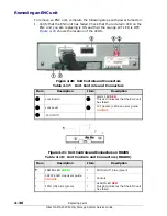
Installing an ENC cable

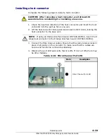
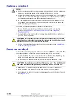
Complete the following steps to install an ENC cable.

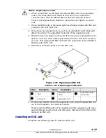
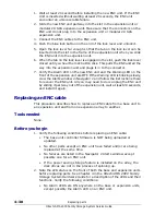
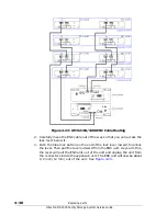
1. Connect the new ENC cable to the ENC unit in the expansion array 

closest to the base unit, or to the controller on the base unit.

2. Connect the other end of the ENC cable to the ENC unit that is partially 

removed from the expansion unit.

3. Make sure that at least 20 seconds has elapsed from the time when you 

removed the ENC unit from the expansion unit. Otherwise, the ENC unit 

will not recover from the failure caused by removing it and will not cycle 

to the Ready state. If that happens, slide the ENC unit out of the 

expansion unit, wait a full 20 seconds, and then reinstall the ENC unit.

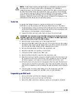
4. Slide the ENC unit into the expansion unit until the tabs on the lock 

levers enter the slots in the frame of the expansion unit.

5. Quickly (within one second) and equally, push the lock levers toward the 

unit until you hear the lock buttons click. 

6. Observe the Alarm light on the ENC unit and verify that it goes out within 

20 seconds after installation.

7. Verify that the green LED on the front of the base unit is ON and that the 

Alarm and Warning LEDs are OFF. (see Note). The green READY LED on 

the front of the base unit may blink rapidly for a maximum of 30 to 50 

seconds before it illuminates.

Replacing parts in a high-density expansion unit

Hitachi Data Systems support policy does not include end-user installation 

or maintenance for model AMS 2500 base unit, the high-density expansion 

unit, or the battery expansion unit.

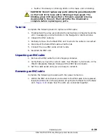
NOTE: If you need to bend an ENC cable to make a connection, keep the 

bends as large as possible. Do not make the radius of the bend any smaller 

than 1-1/4 inches (30 mm) to avoid putting excessive stress on the cable 

and connector.

NOTE: If the Power Saving storage feature is installed on the array, do not 

install a disk drive while the drives are spinning up. Otherwise, the drive 

failure may not recover, the Alarm LED may stay ON, and the unit will not 

cycle to the ready state.

The message “I1GY00 The request of spin up of disk drives is accepted” is 

displayed in the Navigator 2 Alerts window indicates that the drives are 

starting to spin up. If you see this message, wait until the message “spin 

up of disk drives completed” is displayed in the Alerts window in Navigator 

2 before inserting a part.

If you inserted a part while the drives are spinning up, remove the part, 

wait at least 20 seconds, and install the part again. This should clear the 

failure and allow the part to cycle to the ready state. 

Содержание AMS 2100

Страница 1: ...Product version Document organization Getting help Contents FASTFIND LINKS MK 97DF8009EN 17 Hitachi AMS 2000 Family Storage System Service Guide ...

Страница 2: ...n feature and product availability Notice Hitachi Data Systems products and services can be ordered only under the terms and conditions of Hitachi Data Systems applicable agreement s The use of Hitachi Data Systems products is governed by the terms of your agreement s with Hitachi Data Systems Hitachi is a registered trademark of Hitachi Ltd in the United States and other countries Hitachi Data Sy...

Страница 3: ... xviii Safety guidelines xix Personal safety xx Electrical safety xxii Handling of cables on the floor xxiii Handling of under floor cables xxiii Equipment safety xxiv Safety and warning labels xxv Safety and warning labels base unit xxvi Safety and warning labels expansion unit xxvii Warning and safety labels high density expansion unit xxviii Safety and warning labels modular 2U SAS expansion un...

Страница 4: ...se unit front panel 1 9 AMS 2100 2300 base unit rear panel 1 10 AMS 2500 base unit 1 11 AMS 2500 base unit front panel 1 12 AMS 2500 base unit rear panel 1 13 Expansion unit 1 14 Expansion unit front panel 1 14 Expansion unit rear panel 1 16 High density expansion unit 1 17 Modular 2U SAS expansion unit 1 18 System controls 1 19 Switches 1 19 Base unit switches 1 19 Expansion unit switches 1 21 Ba...

Страница 5: ...nit replaceable parts rear 3 12 Modular 2U SAS expansion unit 3 13 Modular 2U SAS expansion unit replaceable parts front 3 13 Modular 2U SAS expansion unit replaceable parts rear 3 14 Other system components 3 14 4 Replacing parts 4 1 Before starting maintenance 4 2 Prerequisites 4 2 Unpacking removing and replacing parts 4 4 Replacing a front bezel 4 5 Tool needed 4 5 Before you begin 4 5 Removin...

Страница 6: ...attery 4 25 Replacing a control unit 4 27 Tool needed 4 27 Before you begin 4 27 Unpacking a control unit 4 27 Verifying a control unit failure 4 27 Replacing a control unit 4 28 Removing a control unit 4 28 Installing a control unit 4 30 Replacing a host connector 4 31 Tool needed 4 31 Before you begin 4 31 Unpacking a host connector 4 31 Removing a host connector 4 32 Installing a host connector...

Страница 7: ...sconnecting the Fibre channel interface cable 5 8 Long term array storage 5 9 6 Troubleshooting 6 1 Getting help 6 2 Troubleshooting tables 6 2 Troubleshooting flowcharts 6 8 Navigator 2 does not start 6 8 Navigator 2 cannot connect to an array 6 9 Recovering from failures 6 10 Troubleshooting based on LED indications 6 12 The power LED does not turn on 6 13 The power LED has turned off 6 14 Ready...

Страница 8: ...viii Contents Hitachi AMS 2000 Family Storage System Service Guide ...
Страница 9: ...ion Intended audience Product version Release notes and readme Document revision level Changes in this revision Document organization Document conventions Convention for storage capacity values Related documents Getting help NOTE The AMS 2500 model is included in this manual for reference only Hitachi Data Systems self service policy does not include customer installation or maintenance for model ...

Страница 10: ...ion 2 supersedes and replaces MK 97DF8009EN 01 MK 97DF8009EN 03 February 2009 Revision 3 supersedes and replaces MK 97DF8009EN 02 MK 97DF8009EN 04 April 2009 Revision 4 supersedes and replaces MK 97DF8009EN 03 MK 97DF8009EN 05 June 2009 Revision 5 supersedes and replaces MK 97DF8009EN 04 MK 97DF8009EN 06 August 2009 Revision 6 supersedes and replaces MK 97DF8009EN 05 MK 97DF8009EN 07 November 2009...

Страница 11: ...out replacing components on a periodic basis to prevent array failures and to maintain optimum performance Chapter 6 Troubleshooting This chapter describes how to configure an Hitachi AMS 2000 Family Storage System Chapter 7 Errors This chapter provides information about the errors and error messages that can be displayed by the Hitachi AMS 2000 Family Storage System software Glossary Defines the ...

Страница 12: ...iable which is a placeholder for actual text provided by the user or system Example copy source file target file Angled brackets are also used to indicate variables screen code Indicates text that is displayed on screen or entered by the user Example pairdisplay g oradb angled brackets Indicates a variable which is a placeholder for actual text provided by the user or system Example pairdisplay g ...

Страница 13: ...s getting started guides for experienced users and host connectivity information The symbol identifies documents that contain initial configuration information about Hitachi AMS 2000 Family storage systems AMS2100 2300 Getting Started Guide MK 98DF8152 Provides quick start instructions for getting an AMS 2100 or AMS 2300 storage system up and running as quickly as possible AMS2500 Getting Started ...

Страница 14: ...running supported operating systems Storage and replication features The following documents describe how to use Storage Navigator Modular 2 Navigator 2 to perform storage and replication activities Storage Navigator 2 Advanced Settings User s Guide MK 97DF8039 Contains advanced information about launching and using Navigator 2 in various operating systems IP addresses and port numbers server cert...

Страница 15: ...d AMS 2500 storage systems ShadowImage keeps data RAID protected and fully recoverable without affecting service or performance levels Replicated data volumes can be split from host applications and used for system backups application testing and data mining applications while business continues to operate at full capacity AMS 2000 Family TrueCopy Remote Replication User Guide MK 97DF8052 Describe...

Страница 16: ...ge System Hardware Guide MK 97DF8007 Provides detailed information about installing configuring and maintaining an AMS 2500 storage system AMS 2000 Family Storage System Reference Guide MK 97DF8008 Contains specifications and technical information about power cables system parameters interfaces logical blocks RAID levels and configurations and regulatory information about AMS 2100 AMS 2300 and AMS...

Страница 17: ...llowing documents describe how to use Hitachi Storage Navigator Modular 2 to perform management and replication activities from a command line Storage Navigator Modular 2 Command Line Interface CLI Unified Reference Guide MK 97DF8089 Describes how to interact with all Navigator 2 bundled and optional software modules by typing commands at a command line Storage Navigator 2 Command Line Interface R...

Страница 18: ...em s The exact content of any messages displayed on Storage Navigator Modular 2 The Storage Navigator Modular 2 configuration information This information is used by service personnel for troubleshooting purposes The Hitachi Data Systems customer support staff is available 24 hours a day seven days a week If you need technical support please log on to the Hitachi Data Systems Portal for contact in...

Страница 19: ...ings and important safety guidelines for using a Hitachi AMS 2100 2300 Storage System Read and understand the information in this section before removing replacing and installing system components This section includes the following key topics Personal safety Electrical safety Equipment safety Safety and warning labels ...

Страница 20: ...t these units Before lifting one of these units always turn off the power to the unit and unplug all data and power cables An expansion unit weighs 88 lbs 40Kg Use at least two people to unpack and install an expansion unit CAUTION Be sure to use at least three people to install the unit in a rack Work carefully to prevent the unit from slipping or falling Be sure to install the base unit at the b...

Страница 21: ...caught in the chassis or mounting hardware Wear safety glasses when working under conditions that are hazardous to your eyes Do not work on the equipment or disconnect cables during a thunderstorm when wearing a wool sweater or other heavy wool clothing or when power is applied Avoid hazards such as moist floors The hard disk drives in the array contain a class 1 laser system that does not emit a ...

Страница 22: ...t the terminals are properly connected to the facility s ground Do not work alone when working close to an energized part Work with another person who can immediately turn off the power in an emergency Before starting work ensure that there are no potential electric hazards in the maintenance area such as insufficient grounding or a wet floor Before starting work note where the emergency power off...

Страница 23: ...r stretched between the racks or arrays Tight cables can be damaged or broken if stretched beyond their specified limits as could happen in an earthquake NOTE The following is an excerpt from 29 CFR 1910 147 The control of hazardous energy lockout takeout in the OSHA Occupational Safety Health Administration U S Department of Labor USA Regulations Lockout device A device that utilizes a positive m...

Страница 24: ... on the equipment because it can fall and injure you or the subsystem may not operate normally The array is provided with ventilating holes on external covers in order to prevent overheating Therefore be sure to leave at least 2 inches 5 cm in front and rear of the array and not block the ventilation holes Otherwise the array may overheat and fail Use specified optional parts cables and connectors...

Страница 25: ... injury or death if instructions are not followed cv ELECTRIC SHOCK HAZARD This symbol warns users of electric shock hazard Failure to take appropriate precautions such as not opening or touching hazardous areas of the equipment could result in injury or death Electrostatic Sensitive The ESD symbol warns users that the equipment is sensitive to electrostatic discharge ESD and could be damaged if u...

Страница 26: ...System Service Guide Safety and warning labels base unit Figure 1 shows the location and content of the warning and safety labels on the base unit Figure 1 Safety and Warning Labels Base Unit The label is affixed at location a or b Either I or II is affixed ...

Страница 27: ...Service Guide Safety and warning labels expansion unit Figure 2 shows the location and content of the warning and safety labels on the expansion unit Figure 2 Safety and Warning Labels Expansion Unit The label is affixed at location a or b Either I or II is affixed ...

Страница 28: ...e Guide Warning and safety labels high density expansion unit Figure 3 shows the location and content of the warning and safety labels on the high density expansion unit Figure 3 Warning and Safety Labels High density Expansion Unit The label is affixed at location a or b ...

Страница 29: ...ge System Service Guide Safety and warning labels modular 2U SAS expansion unit Figure 4 shows the location and content of the warning and safety labels on the modular 2U SAS expansion unit Figure 4 Warning and Safety Labels Modular 2U SAS Expansion Unit ...

Страница 30: ...ly Storage System Service Guide Warning and safety labels battery expansion unit Figure 5 shows the location and content of the warning and safety labels on the Battery Expansion Unit Figure 5 Warning and Safety Labels Battery Expansion Unit kg ...

Страница 31: ...e Expansion Unit disk drive Figure 6 Base Expansion Unit Disk Drive Figure 7 shows the location of the label on the High density Expansion Unit disk drive Figure 7 High density Expansion Unit Disk Drive Figure 8 shows the location of the label on the Modular 2U SAS Expansion Unit disk drive Figure 8 Modular 2U SAS Expansion Unit Disk Drive ...

Страница 32: ...e Guide Fan unit Figure 9 shows the location a or b of the labels on the Fan Unit Figure 9 Fan Unit Label Locations Power supply Figure 10 shows the location of the label on the Power Supplies for the Base Unit Figure 10 Power Supply Label Location for the Base Unit a b ...

Страница 33: ...11 Power Supply Label Location for the Expansion Unit Figure 12 shows the location of the label on the Power Supply for the Expansion Unit Figure 12 Power Supply Label Location for the Expansion Unit Figure 13 shows the location of the label on the Power Supply for the High density Expansion Unit Figure 13 Power Supply Label Location for the High density Expansion Unit ...

Страница 34: ...Unit Figure 14 Power Supply Label Location for the Modular 2U SAS Expansion Unit Figure 15 shows the location of the label on the DC Power Supply for the Base Unit Figure 15 DC Power Supply Label Location for the Base Unit Figure 16 shows the location of the label on the DC Power Supply for the Expansion Unit Figure 16 DC Power Supply Label Location for the Expansion Unit ...

Страница 35: ...i AMS 2000 Family Storage System Service Guide Control unit Figure 17 shows the location of the labels on the Control Unit Figure 17 Control Unit Label Location The label is affixed at location a or b a b AMS 2100 AMS 2300 AMS 2500 ...

Страница 36: ...8 shows the location a or b of the labels on the Cache Memory module Figure 18 Cache Memory Label Location Interface board Figure 19 and Figure 20 show the location a or b of the labels on the FC Interface Boards Figure 19 Fibre Channel Interface Board DF F800 DKF44 DF F800 DKF84 Label Location a b ...

Страница 37: ...Channel Interface Board DF F800 DKF42 Label Location Figure 21 shows the location of the label on the iSCSI Interface Board Figure 21 iSCSI Interface Board Label Location Figure 22 shows the location of the label on the 10 Gbps iSCSI Interface Board Figure 22 iSCSI Interface Board Label Location ...

Страница 38: ...ector Figure 23 Host Connector Label Location unit Figure 24 shows the location of the label on the ENC Unit of the Expansion Unit Figure 24 Unit Label Location for the Expansion Unit Figure 25 shows the location of the labels a or b on the ENC Unit of the High density Expansion Unit Figure 25 Unit Label Location for the High density Expansion Unit a b ...

Страница 39: ...Figure 26 shows the location of the labels a or b on the ENC Unit of the Modular 2U SAS Expansion Unit Figure 26 Unit Label Location for the Modular 2U SAS High density Expansion Unit cable Figure 27 shows the location of the label on the ENC Cable Figure 27 Cable Label Location ...

Страница 40: ... Safety guidelines Hitachi AMS 2000 Family Storage System Service Guide Cable holder Figure 28 shows the locations of the labels a or b on the Cable Holders Figure 28 Cable Holder Label Locations a b a b ...

Страница 41: ... System overview System components System controls NOTE Hitachi Data Systems support policy includes customer installation and maintenance for model AMS 2100 2300 array but not for model AMS 2500 base unit the high density expansion unit or the AMS 2000 Battery Expansion Unit However the Hitachi Data Systems Customer Assist program allows users to upgrade firmware in the AMS 2500 and add or replac...

Страница 42: ...TA drive The high density expansion unit uses either 1 or 2 TB SATA disk drives Each array contains several LEDs that light when certain problems occur making it easy for users to quickly find the source of these problems the LEDs are described in this chapter In addition Chapter 6 Troubleshooting in this manual provides information to assist you to determine the causes of several possible problem...

Страница 43: ...tery expansion unit The Hitachi Data Systems Customer Assist program allows users to upgrade firmware in the AMS 2500 and add or replace disk drives in the RKAK expansion units in an AMS 2500 system When a failure occurs The following is an overview of the maintenance tasks you can perform when a failure occurs on your array See Figure 1 2 1 Failure detection in the subsystem 1 2 Failure notificat...

Страница 44: ...c illustration of a base unit an expansion unit a high density expansion unit an AMS modular 2U SAS expansion unit and a battery expansion unit Figure 1 3 Base Unit Expansion Units and Battery Expansion Unit Hitachi Data Systems Model Hitachi Factory Designation AMS 2100 base unit DF 800 RKS abbreviation RKS AMS 2300 base unit DF 800 RKM abbreviation RKM AMS 2500 base unit DF 800 RKHE2 abbreviatio...

Страница 45: ...nit provides additional storage space and can connect the base unit to additional expansion units or high density expansion units The same high density expansion unit is used with all three base unit models The factory designation for the high density expansion unit is RKAKX Table 1 1 Base Units Hitachi Data Systems Model Hitachi Factory Designation Main Components AMS 2100 RKS 2 redundant power s...

Страница 46: ...Battery expansion units The AMS 2500 supports one or two battery expansion units Each battery expansion unit contains its own charger which is powered by 100 200 VAC A single battery can be connected to both control units If two batteries are installed each battery is connected separately to a different controller See Battery expansion unit LEDs and controls on page 1 40 for detailed information a...

Страница 47: ...eafter referred to as AMS 2100 includes a base unit and from 0 to 7 expansion units Figure 1 4 shows the front above and rear below views of the AMS 2100 base unit The center photo shows the Fibre Channel configuration the lower photo shows the iSCSI configuration The front bezel has been removed in this photo Figure 1 4 AMS 2100 Base Unit Front and Rear Views ...

Страница 48: ...after referred to as AMS 2300 includes a base unit and from 0 to 15 expansion units Figure 1 5 shows the front above and rear below views of the AMS 2300 base unit The center photo shows the Fibre Channel configuration The lower photo shows the iSCSI configuration The front bezel has been removed in this photo Figure 1 5 AMS 2300 Base Unit Front and Rear Views ...

Страница 49: ...front of the unit exposed Both the AMS 2100 and the AMS 2300 unit models are the same on the front Figure 1 6 AMS 2100 Base Unit Front View Table 1 4 AMS 2100 2300 Base Unit Front View Item Description Item Description 1 Disk Drives 4 2nd optional Cache Backup Battery 2 Base Unit Status LEDs See Base unit on page 1 21 for details 5 Switch Panel Power and Mode switches See AMS 2100 base unit on pag...

Страница 50: ... number of Fibre channel host connectors on the controllers the AMS 2100 rear panel is identical to the AMS 2300 The two base units in each model array are identical and can be installed in either slot The base units for the AMS 2100 and the AMS 2300 are described separately in this chapter Figure 1 7 AMS 2100 Base Unit Rear Panel Components Table 1 5 AMS 2100 Base Unit Rear Panel Components Item ...

Страница 51: ...ove and rear below views of the AMS 2500 base unit The center photo shows the Fibre Channel configuration The lower photo shows the iSCSI configuration The front bezel has been removed in this photo Figure 1 8 AMS 2500 Base Unit Front and Rear Views NOTE The AMS 2500 model is included in this manual for reference only Hitachi Data Systems support policy does not include customer installation or ma...

Страница 52: ... removed in the lower photo with the components on the front of the unit exposed Figure 1 9 AMS 2500 Base Unit Front View Table 1 6 AMS 2500 Base Unit Front View Item Description Item Description 1 Cache Backup Batteries See Cache backup battery LEDs on page 1 23 for details 3 Base Unit Status LEDs See Base unit on page 1 21 for details 2 Fan Units 4 Switch Panel Power and Mode switches See AMS 21...

Страница 53: ...AMS 2500 Base Unit Rear Panel Components Table 1 7 AMS 2500 Base Unit Rear Panel Components Item Part Name Description 1 iSCSI Host Ports iSCSI RJ45 Host Connector 1 Gbps 23 Control Unit Controller for AMS 2500 Includes Fibre Channel and or iSCSI interface boards and either 2 GB or 4 GB cache memory unit RAM See AMS 2500 Control Unit Connectors and LEDs on page 1 26 4 Fibre Channel Host Ports Host...

Страница 54: ...S 2000 Family Expansion Unit Front and Rear Views Expansion unit front panel Figure 1 12 shows the front of an expansion unit factory designation RKAK with the decorative bezel installed The front panel of the expansion unit includes Power and Locate status LEDs that show the status of the unit and identify the unit The installation location should provide an unobstructed view of these LEDs In add...

Страница 55: ...unit in the expansion unit Figure 1 12 Front View of an Expansion Unit Figure 1 13 shows the front of an expansion unit factory designation RKAK with the decorative bezel removed and the disk drives in the front of the array exposed Figure 1 13 Expansion Unit Front View Bezel Removed Table 1 8 Expansion Unit Front View Bezel Removed Item Description Item Description Item Description 1 Disk Drives ...

Страница 56: ... connectors used to daisy chain expansion units in the system See Chapter 5 Installation in the Hitachi AMS 2100 2300 Hardware guide MK 97DF8010 for details It also provides LEDs that show the status of the expansion unit and the power supplies that provide power to the expansion unit Expanded views of the expansion unit and detailed descriptions are located on the following pages Figure 1 15 Rear...

Страница 57: ...disk drives two pairs of redundant power supplies and four ENC control units cards The control units manage the drives and are also used to connect the expansion unit to the base unit and to other expansion units Figure 1 16 shows the front above and rear below views of the high density expansion unit The front bezel has been removed in this photo Figure 1 16 High Capacity Expansion Unit Front and...

Страница 58: ...unit The AMS Modular 2U SAS expansion unit contains two redundant power supplies two ENC interface units and from two to 24 SFF disk drives Figure 1 17 shows the front above and rear below views of the AMS Modular 2U SAS expansion unit Figure 1 17 Modular 2U SAS Expansion Unit Front and Rear Views ...

Страница 59: ...rs and drives in a base unit on or off is also located on the front of the unit Facing the front of the base unit this switch is located at the lower right corner Pressing on the right button pushes the right side of the rocker switch and turns the power on Pressing on the left button presses on the left side of the rocker switch and turns the power off Figure 1 18 Base Unit Switches Front Figure ...

Страница 60: ...the right side of the switch labeled To turn the array power OFF press the left side of the switch 2 Mode Switch This sets the Uninterruptable Power Supply UPS mode to either Local Mode or one of three remote modes Leave this switch in the local mode 0 position 1 1 Do not change the setting because it may change the normal operation of the unit NOTE When you turn the power on the array will automa...

Страница 61: ...s are two status LEDs for each disk drive In addition the Cache Backup battery has two status LEDS Figure 1 20 and Table 1 11 describe the front panel status LEDs and their functions Figure 1 20 Base Unit Status LEDs front panel Table 1 11 Base Unit Status LEDs front panel Item Name Color Status Description Base Unit Overall Status LEDs 1 Alarm RED The Alarm LED shows when an AMS 2100 2300 array h...

Страница 62: ...rn off the array 4 Power GREEN ON The base unit is turned on and receiving power OFF The base unit is not turned on AMS 2100 2300 only Disk Drive Status LEDs see photo on page 1 31 1 ALarM LED RED ON Lights when the drive has a serious error OFF Normal Status 2 ACTive LED GREEN ON or Flashing Lights or flashes when the drive is operating and is being read from or written to It indicates that the d...

Страница 63: ... Backup Battery Rear panel LEDs and connectors AMS 2100 2300 The rear panel of the AMS 2100 2300 base unit has several LEDs that indicate the status of the power supplies and control units These LEDs are explained as part of the descriptions of the Control unit LEDs connectors and switches AMS 2100 2300 on page 1 24 and the Base unit power supply status LEDs on page 1 30 Table 1 12 Cache Backup Ba...

Страница 64: ...nectors 4 per controller 7 Reset LED Orange Blinks while the base unit is resetting Connector Path 0 IN 2 Fibre Channel Activity LEDs 2 sets 8 C Power LED Green When on indicates that cache memory is backed up Connector Path 1 IN 3 Lock Lever 2 places 9 10 100 Ethernet management port ACT LED yellow indicates data is being transferred LINK LED green When ON indicates that the link status is normal...

Страница 65: ...is is not an error Table 1 14 LOC LED Number of blinks Description 6 slow Voltage on the control unit is abnormal Reset of the control unit is not canceled 1 fast 1 1 When blinking fast the LED is on for 400 ms and off for 200 ms for each fast blink After the number of fast blinks has completed the LED ID goes off for one second SRAM error 2 fast hard error 3 fast Firmware error in flash memory ON...

Страница 66: ...at the host connector is abnormal GP0 LED GP1 LEDs green indicate that the interface is normal 7 Reset LED orange Blinks while the control unit is resetting Connector Path 2 to ENC unit IN 8 C Power LED green When on indicates that cache memory is backed up Connector Path 3 to ENC unit IN 3 Lock Lever 2 places 9 Maintenance Port LAN 0 ACT LED yellow indicates data is being transferred LINK LED gre...

Страница 67: ...ENC unit IN 2 iSCSI RJ45 Port 1 See item 9 for ACT and Link LED descriptions 8 C Power LED green When on indicates that cache memory is backed up Connector Path 3 to ENC unit IN 3 Lock Lever 2 places 9 Maintenance Port LAN 0 ACT LED yellow indicates data is being transferred LINK LED green When ON indicates that the link status is normal Uninterruptable Power Supply Connector 4 Alarm LED red Indic...

Страница 68: ...ector with the lock opened and the unit ready for removal The second connector is shown capped as all of the host connectors are when the array is shipped The third and fourth ports are shown connected Note that two types of fibre channel cables and connectors are used in this photo Photograph 2 shows a close up view of the two connectors in each data port Photograph 3 shows a host connector parti...

Страница 69: ...res are described on page 1 8 in the Hitachi AMS 2500 Storage System Hardware Guide and also work with an AMS 2500 array The management port accepts either a cross over cable for direct connections to the management port or a straight through cable if connecting to the management port through a switch The port is a standard RJ45 connector that has an amber Port Activity LED on the left side of the...

Страница 70: ...escription 1 Ready LED green on each power supply blinks when the corresponding power receptacle is connected to a working AC outlet even if an AMS 2100 2300 array is not turned on otherwise the LED is OFF 2 Alarm LED red This LED indicates that the power supply has failed Although the other power supply can supply sufficient power and cooling for the array Hitachi Data Systems recommends that you...

Страница 71: ...Hitachi Data Systems recommends that each power supply in the base unit be connected to a different AC source in the rack If one source fails the other source continues to supply power to the other power supply This keeps the array running until power is restored to the failed source NOTE The AMS 2500 base unit does not contain disk drives Figure 1 27 Disk Drive Status LEDs Table 1 18 Disk Drive S...

Страница 72: ...us of the drive installed in the slot directly below the status LEDS As shown in Figure 1 13 on page 1 15 these LEDs are visible when the front bezel is removed A close up photo of the drive status LEDs is shown above There are no switches on an expansion unit Power is turned on and off with a control signal that is routed from the base unit via the ENC cables that are connected to the ENC unit in...

Страница 73: ... AMS 2100 2300 expansion unit has four LEDs that indicate the status of the array Figure 1 30 and Table 1 21 describe the array status LEDs and their functions Figure 1 30 Expansion Unit Status LEDs Table 1 20 Expansion Unit Front View Item Description Item Description Item Description 1 Disk Drives showing the status LEDs 2 Locate LED Expansion unit status LEDs on page 1 33 3 Power LED NOTE The s...

Страница 74: ...curred in the array Please contact Hitachi Data Systems Technical Support See the Getting Help section in the Preface of t his manual 2 Power GREEN ON The base unit is turned ON and receiving power and the power control signal is received by the expansion unit The expansion unit is on and receiving power OFF The base unit is not turned on and or the expansion unit is not receiving power Table 1 22...

Страница 75: ... each fast blink After the number of fast blinks has completed the LED ID goes off for one second Table 1 24 Expansion Unit Rear Panel Component Descriptions Item Description 1 Lock Lever 2 places 2 Alarm LED red This LED indicates that the power supply has failed Although the other power supply can supply sufficient power and cooling for the array Hitachi Data Systems recommends that you replace ...

Страница 76: ...re The installation location should provide an unobstructed view of these LEDs Figure 1 33 High density Expansion Unit Front View Figure 1 34 shows the front panel of a high density expansion unit with the front bezel removed The Locate and Power LEDS are visible with the front bezel off as sell as when it is installed Figure 1 34 High density Expansion Unit Front Panel Table 1 25 High density Exp...

Страница 77: ...Getting help section in the Preface of this manual 2 POWER GREEN ON Normal operation the section is fully operational Slow Blink The firmware download is complete Fast Blink The firmware is downloading do not turn off the array Item Description 1 Alarm LED red This LED indicates that the power supply has failed Although the other power supply can supply sufficient power and cooling for the array H...

Страница 78: ...onnected fails The LOC locate LED for the ENC unit is located on the OUT connector These LEDs are shown in Figure 1 36 Figure 1 36 High density Expansion Unit ENC LEDs Rear Panel The ENC card inside the unit also has ALM and LOC LEDs on the top edge of the card They are visible when the drive cover is removed from the high density expansion unit and are shown in Figure 1 37 Table 1 27 describes th...

Страница 79: ... ENC LED Functions Item Description 1 ALM Alarm RED This LED indicates that the ENC unit has failed 2 LOC Locate ORANGE OFF Normal operation Blinking 6 slow Voltage on the control unit is abnormal Reset of the control unit is not canceled 1 fast 1 1 When blinking fast the LED is on for 400 ms and off for 200 ms for each fast blink After the blinking stops the LED ID goes off for one second SRAM er...

Страница 80: ... LEDs and controls The AMS 2500 can connect to one or two AMS 2000 Battery Expansion Units to extend the life of the data in the cache in case the power to the facility where the unit is installed fails for an extended period Table 1 28 High density Expansion Unit Top View Item Description Item Description 1 Power Supply Area 3 Disk Drive Filler must be in all slots that do not have disk drives in...

Страница 81: ...ition of the battery ON Charge is completed Supplementation charge Low speed blinking 1 second blink every two seconds The battery is not fully charged and is charging High speed blinking 2 blinks per second Abnormal status OFF When the unit is turned off or the battery voltage is abnormal Also when the status of the battery is abnormal See Alarm LED 3 4 Port 1 LED Port 2 LED green ON Lights when ...

Страница 82: ...3 and Table 1 32 on page 1 43 for information about the front panel of the modular 2U SAS expansion unit Figure 1 42 Front Panel Bezel Applied Table 1 31 Modular 2U SAS Expansion Unit Front Bezel Item Description POWER LED green ON expansion unit is receiving power OFF expansion unit is not receiving power READY LED green ON system can be operated Fast blinking internal processing is occurring sys...

Страница 83: ...Panel Table 1 32 Modular 2U SAS Expansion Unit Front Panel Item Description Up to 24 SFF drives Table 1 33 Modular 2U SAS Expansion Unit Back Panel Item Description Alarm LED red ON a failure occurred that makes the array unable to operate Slow Blinking a serious failure has occurred while power is on Please contact Hitachi Data Systems Technical Support See the Getting help section in the Preface...

Страница 84: ...ware error in flash memory Not blinking boot section error of ENC firmware RAM error or ENC hard configuration error Power LED green ON normal operation the section is fully operational Slow Blink firmware download is complete Fast Blink firmware is downloading do not turn off the array IN from RKS RKES RKM RKEM RKH RKHE RKEH or RKAK RKAKS RKAKX PATH IN LED green appears above this connector OUT t...

Страница 85: ...sk drive is operational LOCATE LED orange ON a failure occurred but the modular 2U SAS expansion unit remain operational Table 1 35 Modular 2U SAS Expansion Tray ENC Status LEDs LED Description POWER LED green ON modular 2U SAS expansion tray is receiving power LOCATE LED orange lights when a modular 2U SAS expansion unit ENC has encountered a serious error Please contact Hitachi Data Systems Tech...

Страница 86: ...the modular 2U SAS expansion tray is linked up PATH 0 OUT Side green ON OUT side of the modular 2U SAS expansion tray is linked up Table 1 36 Modular 2U SAS Expansion Tray Power Supply Status LEDs LED Description RDY LED green ON normal operation AC IN LED green AC input to the modular 2U SAS expansion tray is operating normally ALM LED red ON power supply has stopped or is in an abnormal state Ta...

Страница 87: ... Service Guide 2 Identifying failed parts This chapter describes how to verify a failed part and how to order a failed part The following key topics are covered Identifying a failed part Identifying the cause of a failure Locating the failure Ordering replacement parts ...

Страница 88: ...view or the process to locate a failed component and replace it Figure 2 1 Identifying and Recovering from a Failure Recognize failure Start Navigator 2 Use Navigator 2 to check the status of the failed array Starts normally Refer to the Troubleshooting chapter for causes and fixes Does not start Navigator 2 cannot access the array Make sure that the array is turned on is connected to the LAN and ...

Страница 89: ...re 2 2 Checking the Mail or SNMP that Notified you of a Failure b If you have already located the array by observing warning or failure lights obtain the serial number from the label as shown in Figure 2 3 Figure 2 3 Locations of Array Serial Number Labels NOTE It is possible to use a system that does not have Navigator 2 installed After starting the web browser enter the above URL in the address ...

Страница 90: ...hat window Table 2 2 Checking the Serial number and Status of an Array Item Description Item Description 1 Locate the array serial number 2 Check the array status NOTE Status Conditions When the status is Normal the array is operating normally and the management node on which Navigator 2 is installed is communicating normally with the array Check the connection between the array and the host When ...

Страница 91: ...ts in the array 2 Select the parts that have failed and click Show Details at the lower right corner of the window The Failed Parts dialog box is displayed Figure 2 5 Alerts Events Window 3 Check the details of the failed part Click the support portal web site link after checking the failed part details NOTE If the management host that has Navigator 2 installed is not connected to the Internet not...

Страница 92: ...Window 1 4 Order the parts to be replaced a Note the information as shown in the above example b Open a web browser and go to the Hitachi Data Systems support site Follow the support portal Web instructions Table 2 3 Alarm Information Window Item Description Item Description 1 Click here 2 Information for order ...

Страница 93: ... can be replaced with the power turned on This chapter covers the following key topics Overview Base unit AMS 2500 base unit parts front Expansion unit NOTE The AMS 2500 model is included in this manual for reference only Hitachi Data Systems support policy does not include customer installation or maintenance for model AMS 2500 except for firmware upgrades and disk drives in the expansion units ...

Страница 94: ...el Unit Part Notes AMS 2100 2300 Base unit Front Bezel Disk Drive Power Supply Backup Battery Control Unit Host Connector Customer replaceable parts Expansion unit Front Bezel Disk Drive Power Supply unit cable Customer replaceable parts Hi Capacity Expansion Unit Front Bezel Disk Drive Power Supply unit cable No customer replaceable parts FE only Modular 2U SAS expansion unit Front Bezel Disk Dri...

Страница 95: ... unit Front Bezel Disk Drive Power Supply unit cable Replaceable by Hitachi Data Systems support personnel only except for disk drives which are customer replaceable Hi Capacity Expansion Unit Front Bezel Disk Drive Power Supply unit cable No customer replaceable parts FE only Modular 2U SAS expansion unit Front Bezel Disk Drive Power Supply unit cable No customer replaceable parts FE only Table 3...

Страница 96: ...eable parts on the base unit AMS 2100 2300 base unit replaceable parts front The base unit front bezel is shown here It is shipped with a standard key that fits the front bezel on both the base and expansion units Figure 3 1 shows the base unit with the front bezel removed Figure 3 1 Base Unit Replaceable Parts Front ...

Страница 97: ...138 B SAS Disk Drive Canister Unit 400 GB Drive 3276308 A SAS Disk Drive Canister Unit 450 GB Drive 3276138 C SAS Disk Drive Canister Unit 500 GB Drive 3276139 A SATA Disk Drive Canister Unit 600 GB Drive 3276138 D SAS Disk Drive Canister Unit 600 GB Drive 3282360 A SAS SED Disk Drive Canister Unit 1 TB Drive 3276139 C SATA Disk Drive Canister Unit 2 TB Drive 3276139 D SATA Disk Drive Canister Uni...

Страница 98: ...3 6 Replaceable parts Hitachi AMS 2000 Family Storage System Service Guide ...
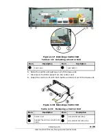
Страница 99: ...t bezel on both the base and expansion units Figure 3 3 Base unit with the front bezel removed Figure 3 4 shows the base unit replaceable parts Table 3 3 Base Unit Replaceable Parts Rear Item Part Name Part No Remarks 1 Power Unit RK 3276080 A Power supply for AMS 2100 AMS 2300 RKS RKM 2 Control Unit SFC2 3282005 C Controller for AMS 2100 RKS Includes 4 Gbps Fibre Channel interface board and 2 GB ...

Страница 100: ...Table 3 4 AMS 2500 Base Unit Replaceable Parts Front No Part Name Part No Remarks 1 Optional Cache Backup Battery N1K 3276079 A Cache Backup Battery 2 2 Fan Unit 3276374 A FAN Assembly for AMS 2500 RKHE2 3 Cache Backup Battery N1K 3276079 A Cache Backup Battery 2 4 Front Bezel 3276156 A Front Bezel Assembly for AMS 2500 RK2 RKHE2 ...

Страница 101: ...placeable Parts Rear Table 3 5 AMS 2500 Base Unit Replaceable Parts Rear Item Part Name Part No Remarks 1 iSCSI Connector 23 Control Unit 3282006 A 2 GB RAM 3282006 B 4 GB RAM Controller for AMS 2500 Includes Fibre Channel interface board and either 2 GB or 4 GB cache memory unit RAM 4 Host Connector 3276337 A 3276337 B Host Connector 4 Gbps Host Connector 8 Gbps 5 Power Unit 3276255 A Power suppl...

Страница 102: ...sion unit Expansion unit replaceable parts front The expansion unit front bezel is shown in Figure 3 6 It is shipped with a standard key that fits the front bezel on both the base and expansion units Figure 3 6 Expansion Unit front bezel and key Figure 3 7 shows the expansion unit replaceable parts Figure 3 7 Expansion Unit Replaceable Parts Front ...

Страница 103: ...76308 A SAS Disk Drive Canister Unit 450 GB Drive 3276138 C SAS Disk Drive Canister Unit 500 GB Drive 3276139 A SATA Disk Drive Canister Unit 600 GB Drive 3276138 D SAS Disk Drive Canister Unit 600 GB Drive 3282360 A SAS SED Disk Drive Canister Unit 1 TB Drive 3276139 C SATA Disk Drive Canister Unit 2 TB Drive 3276139 D SATA Disk Drive Canister Unit 200 GB Drive 3282195 B Flash Disk Drive Canister...

Страница 104: ...t replaceable parts rear Figure 3 8 Expansion Unit Replaceable Parts Rear Table 3 7 Expansion Unit Replaceable Parts Rear Item Part Name Part No Remarks 1 Enclosure Control Unit 3276159 A Controller for expansion unit 2 Power Supply 3276081 A Replaceable power supply for RKAK expansion unit ...

Страница 105: ... in Figure 3 9 It is shipped with a standard key that fits this unit only Figure 3 9 Modular 2U SAS Expansion Unit Front Bezel and Key Figure 3 10 shows the replaceable parts on the front of the modular 2U SAS expansion unit Figure 3 10 Modular 2U SAS Expansion Unit Replaceable Parts Front Table 3 8 Modular 2U SAS Expansion Unit Replaceable Parts Front Item Part Name Part No Remarks 1 Canister Uni...

Страница 106: ... density expansion unit The AMS 2500 also supports rack mounted battery expansion units Chapter 1 in this service guide contains information about these units for reference However these units are not customer installable serviceable or replaceable If you need assistance with these units please contact your authorized Hitachi Data Systems service representative Table 3 9 Modular 2U SAS Expansion U...

Страница 107: ...ly Replacing a backup battery Replacing a control unit Replacing a host connector Replacing an ENC unit Replacing an ENC cable Replacing parts in a high density expansion unit NOTE Hitachi Data Systems support policy does not include end user installation or maintenance for model AMS 2500 base unit the high density expansion unit or the battery expansion unit However the Hitachi Data Systems Custo...

Страница 108: ... or replacing hardware components If a part is installed or configured incorrectly it is possible to lose data from the system Hitachi Data Systems strongly recommends that you back up your data to a remote array before beginning hardware upgrades or replacements When hot swapping parts complete the installation of the replacement part within ten minutes If a slot in any unit in the array is left ...

Страница 109: ...ont of the base unit is blinking at high speed When it is blinking at high speed the ENC firmware is being downloaded Depending on the LAN connection and traffic on the LAN this could take from 30 tor 50 minutes on an AMS 2100 2300 or from 40 to 60 minutes on an AMS 2500 Wait at least 30 seconds after the Ready LED lights steadily before making any changes to the hardware 6 Warning LED Status Do n...

Страница 110: ...lic accessories or a watch in order to avoid an electric shock Do not to touch any live parts with a screwdriver or other object CAUTION Do not disassemble or modify any replacement parts Most of the parts are precision devices that can be damaged if handled or used incorrectly dropped or disassembled You could also injure yourself or others by incorrectly handling or using the parts that are heav...

Страница 111: ... both sides and above the center of the unit Pull the front bezel toward you to disengage it from the ball catches The bezel will then swing outward at the top 3 Disengage the two hooks of the front bezel from the slots on the array chassis by lifting the bezel upward and then pulling it out and away from the base or expansion unit Figure 4 1 Removing the Front Bezel CAUTION Attach and remove the ...

Страница 112: ...the bottom right part of the front bezel then pull the front bezel toward you and disengage the right side of the front bezel from the ball catches 3 Remove the front bezel from the claws on the left side of the array s main body Figure 4 2 Removing the Front Bezel on the Modular 2U SAS Expansion Unit Table 4 1 Removing the Front Bezel Item Description Item Description 1 Hook on back side of bezel...

Страница 113: ... front bezel to the modular 2U SAS expansion unit 1 Insert the key into the keyhole on the front bezel and unlock the lock 2 Insert the claw on the front side of the subsystem main body into the claw hole in the front bezel 3 Fix the front bezel by pressing the right side of the front bezel to engage the hook of the front bezel with the ball catch 4 Remove the key from the front bezel and store it...

Страница 114: ...is not set When the RAID group and logical unit are deleted or formatted related user data will be lost Disk drives must be removed and replaced with the power on When hot swapping parts do not leave any slot in the array open for more than ten minutes Otherwise the loss of cooling air could cause the unit to overheat and shut down Wait at least 20 seconds after removing a part from the system bef...

Страница 115: ...he message I1GY00 The request of spin up of disk drives is accepted is displayed in the Navigator 2 Alerts and Events window indicates that the drives are starting to spin up If you see this message wait until the message spin up of disk drives completed is displayed in the Alerts and Events window in Navigator 2 before installing a part If you have inserted a part while the drives are spinning up...

Страница 116: ...the disk drive numbering on the modular 2U SAS expansion unit is 0 to 23 from the left to right viewed from the front of the unit Figure 4 4 Modular 2U SAS Expansion Unit Disk Drive Numbering Table 4 2 Base and Expansion Unit Disk Drive Numbering Item Description Item Description Item Description 1 Base Unit 2 Expansion Unit 0 14 Disk Drive Slot Numbers ...

Страница 117: ... ready state the data from the failed disk is automatically copied to the replacement disk and the failure recovery is displayed in Navigator 2 8 Launch Navigator 2 and display the Alerts window 9 Double click the disk drive under Recovery Procedure indicated in yellow in the Component Status Tag Verify that the failure has recovered 10 Verify that the Warning LED on the front panel of the base un...

Страница 118: ...gs it from the connectors inside the unit 3 Holding the disk drive as shown in Figure 4 5 or Figure 4 6 for the modular 2U SAS expansion unit carefully slide the disk drive out of the unit and place it in a static protective bag 4 Follow the instructions below to install a replacement disk drive Figure 4 5 Removing a Disk Drive Figure 4 6 Removing a Disk Drive Modular 2U SAS Expansion Unit Table 4...

Страница 119: ...dy done so put on an anti static wrist strap 2 Unpack the new disk drive and put the drive on an antistatic mat 3 If you are adding a new disk drive to expand storage capacity loosen the mounting screws and remove the filler dummy disk drive cover from the slot where you want to install the new drive You may note that cooling air is coming out of the open slot NOTE If you are installing multiple d...

Страница 120: ...n up as soon as it is fully inserted into the slot and is connected electrically to the unit If the drive is a replacement for a failed drive as soon as the replacement drive is operational the system will begin copying data to it It takes approximately 1 1 2 minutes to copy the data to the new drive 7 Repeat steps 3 through 6 for each disk drive that you are installing or replacing 8 When you hav...

Страница 121: ...Replacing parts 4 15 Hitachi AMS 2000 Family Storage System Service Guide Figure 4 10 Installing a Disk Drive into Modular 2U SAS Expansion Unit ...

Страница 122: ...gator 2 a RKS RKM Power Unit 1 b RKAK Lever Lever Power Unit 0 Power Unit 1 Power Unit 0 ALM LED RDY LED ALM LED RDY LED Button blue Button blue RDY LED ALM LED Power Unit 1 Power Unit 0 Lever c RKAKS NOTE The power supplies for the base unit and expansion unit are different models Check the model number on the failed power supply before ordering a new one and check the model number on the new pow...

Страница 123: ...at has the power turned on Loss of cooling air can cause the unit to overheat and shut down When replacing both power supplies replace them one at a time or replace both of them while the power is turned off When the power supply and another module fail at the same time replace the power supply first Otherwise a powering off subsystem down may occur because of an abnormal temperature rise Do not r...

Страница 124: ...d replacing for some other reason turn the power off and then replace both units Table 4 4 AMS 2100 2300 Base Unit Power Supply LEDs AMS 2100 2300 Item Description 1 Ready LED green on each power supply blinks when the corresponding power receptacle is connected to a working AC outlet even if an AMS 2100 2300 array is not turned on otherwise the LED is OFF 2 Alarm LED red This LED indicates that t...

Страница 125: ...f the unit and unplug the power supply from the connectors inside the unit The power supply will now be about 1 2 12 mm out of the unit as shown below 4 Using both hands slide the power supply out of the unit See Figure 4 12 Table 4 5 Base Unit Power Supply Safety Components Item Description 1 Power Cable Retainer 2 Safety Lock Table 4 6 Unlocked Base Unit Power Supply AMS 2100 2300 Item Descripti...

Страница 126: ...eplacing parts Hitachi AMS 2000 Family Storage System Service Guide Figure 4 12 Base Unit Power Supplies Table 4 7 Base Unit Power Supplies Item Description Item Description 1 Power Supply 0 2 Power Supply 1 ...

Страница 127: ... the lever Then pull the lever outward and away from the power supply As you do this the lever will unplug the power supply from the connectors inside the unit The power supply is now about 1 2 12 mm out of the unit Figure 4 14 Expansion Unit Power Supply Partly Removed NOTE The AC power supply includes a safety lock that prevents the lock lever from being opened until the power cable is disconnec...

Страница 128: ...t accidentally become unplugged The power supply turns on as soon as the power cord is plugged in There is no switch on the supply 4 When the power supply is plugged in it immediately does a self test during which time the green Ready light on the front of the supply is blinking When the power supply is operating normally the light changes from blinking to ON The test takes about 20 seconds 5 Afte...

Страница 129: ... See Chapter 2 Identifying failed parts CAUTION The backup battery in the base unit must be removed and replaced with the power turned on When the power is turned off during replacement user data on the cache that has not been written on a disk is not backed up because the power is not supplied from the battery When hot swapping a part do not leave any slot in the array open for more than ten minu...

Страница 130: ... from the connectors in the unit and pull it about 1 2 inch 13 mm out of the unit 3 Holding the battery with both hands slide it out of the base unit Table 4 10 Cache Backup Battery Item Description Status 1 Lock Lever When the lock lever is closed and the blue button is fully extended the battery is secured to the array 2 Alarm LED RED When on indicates that the battery has failed When off indica...

Страница 131: ... is installed on the left side of the array 2 Lock Lever 3 Cache backup battery unit 0 NOTE If a cache backup battery is inserted without waiting 20 seconds it may not recover from the failure If that happens unlock the battery and slide it partway out of the base unit only far enough to unplug it wait at least 20 seconds and then resinsert the battery into the base unit NOTE Do not install a batt...

Страница 132: ...p to 24 hours 5 Verify that the Ready LED on the backup battery is ON 6 Verify that the green Ready LED on the front of the base unit is on steadily and the red Alarm and orange Warning LEDs are not ON The green Ready LED on the front of the base unit may blink rapidly for a maximum of 30 to 50 minutes 7 Attach the front bezel 8 The backup battery is not repairable Recycle the removed backup batte...

Страница 133: ... control unit has failed See Chapter 2 Identifying failed parts NOTE Please contact Hitachi Data Systems Support Center before replacing a control unit Static sensitive Ground yourself before touching CAUTION When hot swapping a part do not leave any slot in the array open for more than ten minutes Otherwise the loss of cooling air could cause the unit to overheat and shut down Do not replace any ...

Страница 134: ...i static wrist strap 3 Disconnect all cables except the ENC cables from the control unit 4 Push the blue lock buttons on the lock levers to unlock them 5 Pull outward on both lock levers to disengage the connectors in the unit See Figure 4 17 NOTE In the unlikely event the array power is on and both control units in a base unit fail at the same time replace them one at a time The system parameters...

Страница 135: ...control unit 8 Grasp the control unit with both hands and slide it out of the base unit Figure 4 18 Removing a Control Unit Table 4 12 Unlocking a Control Unit Item Description Item Description 1 Lock Lever 2 Lock Button Table 4 13 Removing a Control Unit Item Description Item Description 1 Control Unit 3 Anti static Wrist Strap 2 Support the control unit with both hands 4 Anti static Wrist Strap ...

Страница 136: ...rol unit usually recovers in about three minutes but if the I O load from the host computer is high it may take three minutes or more to recover 5 Connect all of the cables to the control unit When connecting the Fibre Channel interface cables insert the Fibre Channel interface cables until they are completely seated in the host connectors If the fibre channel Interface cables are partially insert...

Страница 137: ...re replacing parts See Chapter 4 in the Hitachi AMS 2100 2300 Storage System Hardware Guide for a description of the LEDs and their functions Verify the following conditions No Alarm LEDS are ON anywhere on the base unit except the HALM Host Alarm LED on a control unit The Warning LED on the base unit is not blinking Unpacking a host connector 1 If you have not already done so put on an anti stati...

Страница 138: ...failed host connector See the following illustration 2 Unlock the host connector Pull down and outward on the host connector lock bar to unlock 3 Slide the host connector out of the base unit and put it on an antistatic mat or into a static protective bag Figure 4 19 Removing a Host Connector Table 4 14 Fibre Channel Cable Retainer Item Description 1 Fibre Channel Cable Retainer Table 4 15 Host Co...

Страница 139: ...nect the fibre channel cables Ensure that the cable retainer locks in place Pull gently on the connector to make sure that the cables are secure and cannot be removed accidentally 4 Observe the port LED and verify that it is ON If it is not ON there may be other failures CAUTION After removing a host connector wait at least 20 seconds before reinstalling it or installing a new one NOTE If using an...

Страница 140: ...Hitachi AMS 2000 Family Storage System Hardware Guide for a description of the LEDs and their functions Verify the following conditions No Alarm LEDS are ON anywhere on the base expansion units or modular 2U SAS expansion unit except the Alarm LED on the ENC unit you are replacing Neither the Ready or Warning LEDS on the base unit is blinking NOTE Please contact Hitachi Data Systems Support Center...

Страница 141: ... you slide the ENC unit into the unit 10 When the tab on the lock lever is engaged in the slot push the lock lever closed until you hear the lock button click This pulls the ENC unit all the way into the expansion unit or modular 2U SAS expansion unit and plugs it in 11 The firmware from the other ENC unit in the expansion unit will automatically be loaded onto the ENC unit you just installed Unpa...

Страница 142: ...EDS Figure 4 20 Unit Controls and Connectors Figure 4 21 Unit Controls and Connectors on RKAKS Table 4 17 Unit Controls and Connectors Item Description Item Description 1 Lock Button 4 Alarm LED RED This LED indicates that the ENC unit has failed 2 Lock Lever 5 LCT locate LED See users guide ORANGE 3 Port OUT Table 4 18 Unit Controls and Connectors RKAKS Item Description Item Description POWER LED...

Страница 143: ... If removing the ENC unit on the modular 2U SAS expansion unit raise and pull toward you the right and left levers that secure the ENC unit to remove the ENC unit Installing an ENC unit Complete the following steps to install an ENC unit NOTE Replacement order When a controller on the base unit and an ENC unit in an expansion unit in the same path have failed at the same time replace the controlle...

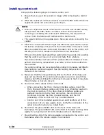
Страница 144: ...on unit are OFF If the Warning LED is blinking slowly view the Alerts window in Navigator 2 and follow the instructions there to recover the ENC unit All you may need to do is unplug the ENC unit by sliding it part way out of the expansion unit wait at least 20 seconds and install it again Replacing an ENC cable This procedure describes how to replace an ENC cable from a base unit to an expansion ...

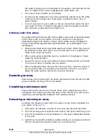
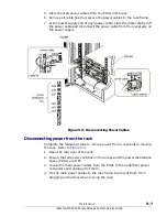
Страница 145: ... the ENC cable from its shipping container 2 Verify that you have the correct cable See Chapter 3 Parts List in the Hitachi Adaptable Modular Storage 2100 2300 Service Guide 3 Set the cable aside until you are ready to install it Removing an ENC cable Complete the following procedure with the power turned on 1 Within the ENC units that are connected to the ENC cable to be replaced locate the ENC u...

Страница 146: ...ou can access the lock lever below it 3 Push the blue lock button on the end of the lock lever inward to unlock the lever Then pull the lever outward from the ENC unit As you do this the lever will pull the ENC unit out of the unit and unplug the unit from the connectors inside the expansion unit The ENC unit will now be about 1 2 inch 12 mm out of the unit See Figure 4 24 ...

Страница 147: ...t in the process 5 Disconnect the other end of the ENC cable from the ENC unit or control unit to which it is attached It is not necessary to remove that ENC unit or the controller Table 4 20 Unit Controls and Connectors Item Description Item Description 1 Lock Button 4 Alarm LED RED This LED indicates that the ENC unit has failed 2 Lock Lever 5 LCT locate LED See users guide ORANGE 3 Port OUT ...

Страница 148: ...d Warning LEDs are OFF see Note The green READY LED on the front of the base unit may blink rapidly for a maximum of 30 to 50 seconds before it illuminates Replacing parts in a high density expansion unit Hitachi Data Systems support policy does not include end user installation or maintenance for model AMS 2500 base unit the high density expansion unit or the battery expansion unit NOTE If you ne...

Страница 149: ...ation about replacing components on a periodic basis to prevent array failures and to maintain optimum performance The following key topics are covered Before starting general maintenance Inspecting and cleaning the array Checking for loose or damaged cables or connectors Moving an array Long term array storage ...

Страница 150: ...e average operation hours of the array is 400 hours month Change the intervals according to the operating hours per month of your system See Table 5 2 Table 5 2 Changing Maintenance Intervals Task Factors requiring change of maintenance interval Remarks Reasons to shorten maintenance intervals Reasons to lengthen maintenance intervals Inspecting fans Cleaning the array Long operating hours Install...

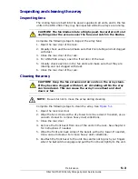
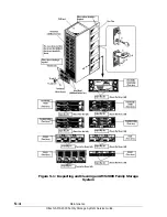
Страница 151: ...ee Figure 5 1 1 Open the rack rear door 2 Wipe the fan screens with a dry towel to remove dust If needed use a vacuum cleaner to remove heavy dust collections 3 Close the rear door 4 Remove the front bezel from one of the units in the rack See chapter 4 for instructions if needed 5 Wipe the front and back sides of the bezels with a dry towel If needed Use a vacuum cleaner to remove heavy dust coll...

Страница 152: ...5 4 Maintenance Hitachi AMS 2000 Family Storage System Service Guide Figure 5 1 Inspecting and Cleaning an AMS 2000 Family Storage System ...

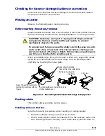
Страница 153: ...iscusses cable routing issues Handling cables on the floor Note the following precautions when handling or routing cables Route the cables so that you do not trip on them Protect cables which cannot be routed within a rack and are laid on the floor including across a doorway Use a cable duct to prevent wear on CAUTION Generally each part is equipped with high precision components Remove and instal...

Страница 154: ...er When using cable protecting duct be careful not to damage or break cables by catching them Be sure to insert or pull out a cable connector holding it with your hand If you pull a cable a trouble may be caused When bending the Fibre Channel I F cable and RC cable to connect it give it a bend with a long radius not less than 30 mm so as not to apply the cable and the connector excessive stresses ...

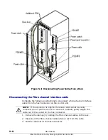
Страница 155: ...acle on the power supply Figure 5 3 Disconnecting Power Cables Disconnecting power from the rack Complete the following steps to remove power from a rack before moving the rack Refer to Figure 5 4 1 Open the rear door of the rack 2 Ensure that all power switches on the arrays and the power distribution buses PDUs are OFF 3 Locate the main power cables from the PDUs to the underfloor power connecto...

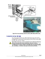
Страница 156: ...e channel interface cable from the host connector on the control unit 1 Remove the clamps 1 holding the Fibre channel cables to the rack 2 Disconnect the Fibre channel cable retainer 2 from the cable 3 Pull the cable out of the host connector NOTE If the connector is tight in the socket and cannot be easily removed do not pull hard on it to remove it Instead gently wiggle the cable out of the sock...

Страница 157: ...use an array for six months or more move the batteries to a system that is being used or turn the array on for at least 24 hours once every six months CAUTION If the array is not energized for more than 6 months the battery will likely discharge completely When the battery completely discharges it may be damaged and you may not be able to recharge it To prevent this from happening charge the batte...

Страница 158: ...5 10 Maintenance Hitachi AMS 2000 Family Storage System Service Guide ...
Страница 159: ...chapter provides information to help you identify and resolve problems that you may encounter with a Hitachi AMS 2000 Storage System The following key topics are covered Getting help Troubleshooting tables Troubleshooting flowcharts Recovering from failures Troubleshooting based on LED indications ...

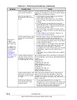
Страница 160: ... with host 1 Verify that the port activity LEDs on the Fibre Channel data ports being used are is ON If not try a different Fibre Channel data port 2 Check the LUN Manager mapping and LUN settings Array or part has failed Array or part has failed 1 Start Navigator 2 If it fails to start see Navigator 2 does not start on page 6 8 2 Go to the Explorer pane and select Resources Arrays 3 In the Array ...

Страница 161: ...steps do not fix the problem you may need to reinstall the Navigator 2 software Corrupt Navigator 2 installation Reinstall Navigator 2 See Chapter 7 in the Hitachi AMS 2100 2300 and AMS 2500 Hardware Guides Navigator 2 does not run Incorrect communication setting Negotiation Check the negotiations settings on the management console and array Make sure they are the same The default value for the ne...

Страница 162: ...t the array be set to statically Static assign IP address If the IP address is not assigned from the DHCPv4 server to the array when the array is set to use the DHCPv4 server Navigator 2 cannot be connected to the array Consult with your network administrator and review the DHCPv4 server settings The default value is DHCPv4 Off uses a Static IP address Communication failure an incorrect value set ...

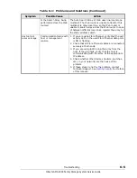
Страница 163: ...ilure with host or management console 1 If you are using Fibre Channel verify that the port activity LED on the used Fibre Channel data ports is ON or flashing 2 Check that all Fibre Channel cables are connected securely at both ends 3 If you are using iSCSI ping the array from the host If the ping fails verify that the host is communicating with the array at the appropriate IP address 4 Check whe...

Страница 164: ...ully operational Use the array normally Ready LED fast blink Not a failure The firmware is being updated do not turn off the array Wait until the light is ON steady before attempting to replace parts or use the array Warning LED ON Nonserious Error The base unit can continue to operate See the Alerts Events window in Navigator 2 for information about the error Alarm LED ON A serious error has occu...

Страница 165: ...not plugged in 3 PDB switch or breaker OFF 4 No electric supply to rack 1 Ensure that the ENC cables are connected from the base unit to the expansion unit and that Ensure that the array power switch is ON 2 Check that the power cable connections to the expansion unit and the PDB are secure 3 Ensure that the PDB switches in the rack are ON 4 Verify electricity supply to the rack Work with facility...

Страница 166: ... different systems verify that the host on which Navigator 2 is installed is running Verify that the correct address is entered When the host and client systems have different network settings consult with the network admin and check the settings of both systems Consult your host administrator and check the firewall setting Consult your host administrator and check the firewall setting Reinstall N...

Страница 167: ...turned on Power LED is OFF Ready LED is ON Ready LED is OFF Check the Alarm LED on the selected array Alarm LED is ON Cycle the power switch wait for the Ready LED to come on and check the Alarm LED Repeat three times Alarm LED is ON Check the Ready LED on the selected array and verify that it is ON Yes No Contact Net work Admin Ready LED is ON Ready LED is OFF Alarm LED is OFF Turn the power swit...

Страница 168: ... occurs perform the following steps to recover form the failure 1 Log in to Navigator 2 Enter the following URL in the address field in the web browser http IP address of management console PC 23015 StorageNavigatorModular Login 2 The Array List window is displayed 3 In the Arrays area check the status and serial number of the array where the failure occurred see Figure 6 3 on page 6 10 Figure 6 3...

Страница 169: ...cannot communicate with the array in Table 6 1 Problems and Solutions on page 6 2 6 From the Arrays area shown in Figure 6 3 click the name of the array When the next screen appears click either Alerts Events in the Array List window or Check for Errors in the Common Array Tasks area In the Alert Parts tab check for the failed part such as a disk drive see Figure 6 4 If a disk drive is shown repla...

Страница 170: ...information click Close Figure 6 5 Example of an Alarm Information Window Troubleshooting based on LED indications This section provides step by step procedures to help determine the cause of failures that are indicated by the LEDs on the array This section is intended to be used along with Table 6 2 LED Failure Indications on page 6 6 Verify that a failure is recovered after taking the appropriat...

Страница 171: ...ths of TrueCopy remote replication TrueCopy Extended Distance are blocked At the time the path is blocked Navigator 2 sends a failure notice to the users whose email addresses are configured in the Alerts and Events window in Navigator 2 The alert contains information regarding the Email Alert and SNMP Agent Support features and TRAP Follow the instructions in the email alert After the remote unit...

Страница 172: ...ven when the READY LED green blinks the subsystem is operational No Refer to Ready LED does not turn on next section 7 End of procedure Ready LED does not turn on This procedure is also used when the Ready LED has turned on once and then turns off 1 Is the Power LED on the base unit on Yes Go to step 2 No Go to step 4 in The Power LED does not turn on 2 Is the Alarm LED on the base unit on Yes Ref...

Страница 173: ...i AMS 2000 Family Storage System Service Guide for instructions Warning LED has turned on or blinks 1 Does the WARNING LED orange blink at high speed Yes Wait until the WARNING LED orange on the base unit is off and the READY LED green on the base unit lights because the firmware is being updated No Go to step 2 2 Does the WARNING LED on the base unit blink at low speed Yes Use Navigator 2 to iden...

Страница 174: ...hen an unknown failure occurs in an array The troubleshooting flowchart in Figure 6 6 describes the procedure to identify and repair a failed part when Navigator 2 does not display the failed part information Figure 6 6 Recovering a Failure That Cannot Specify the Failed Part ...

Страница 175: ...mily Storage System Service Guide 7 Errors This chapter provides information about the errors and error messages that can be displayed by the Hitachi AMS 2000 Storage System software The following key topic is covered Error recovery ...

Страница 176: ...e failure is changed to the data disk see Note W061HH Spare HDU alarm Unit x HDU y W0Bzab Spare HDU alarm Unit x HDU y W0Czab SATA Spare HDU alarm Unit x HDU y Spare Disk blocked see Note This message I1GG00 has set Spare Drive of Configuration Settings Restore Options of the Hitachi Storage Navigator Modular 2 to variable default value This message is displayed after the disk drive restoration is...

Страница 177: ...ed Completion of data area recovery I008xy Data recovery to spare HDU I008HH Data recovery to spare HDU Completion of recovery onto Spare Disk I1GG00 HDU changed to spare Unit x HDU y The blocked data disk is changed to the spare disk and the spare disk before the failure is changed to the data disk see Note W060HH HDU alarm W09zab HDU alarm W0Azab SATA HDU alarm Data Disk is blocked see Note W061...

Страница 178: ...Disk Drive restoration is completed if the Disk Drive capacity of the blocked Disk Drive and the Spare Disk Drive at the data recovery destination is matched when Spare Disk Drive Active Mode is variable and Applying No Copy Back Mode on All the Units is set to enable However when the Power Saving function is installed and enabled if the Spare Disk setting is made for the Disk Drives 0 to 4 of the...

Страница 179: ...f the Fibre Channel or S ATA Disk Drives that configures the RAID Group increases The correction copy copy back and dynamic sparing do not operate mutually at the same time and also they do not operate at the same time for two or more Disk Drives Therefore when the data of two or more Disk Drives n Disk Drives was recovered the time that it takes to complete recovering all the data of the n Disk D...

Страница 180: ...12D 1P 120 240 380 360 16 Disk Drives 15D 1P 140 280 440 420 4 Disk Drives RAID 1 0 2D 2D 40 80 130 120 8 Disk Drives 4D 4D 40 80 130 120 16 Disk Drives 8D 8D 40 80 130 120 2 Disk Drives RAID 1 1D 1D 40 80 130 120 AMS 2500 4 Disk Drives RAID 6 2D 2P 30 60 90 90 6 Disk Drives 4D 2P 50 100 160 150 10 Disk Drives 8D 2P 80 160 250 240 14 Disk Drives 12D 2P 120 240 380 360 18 Disk Drives 16D 2P 150 300...

Страница 181: ...RAID 5 4D 1P 40 80 130 120 16 Disk Drives 15D 1P 40 80 130 120 4 Disk Drives RAID 1 0 2D 2D 40 80 130 120 16 Disk Drives 8D 8D 40 80 130 120 2 Disk Drives RAID 1 1D 1D 40 80 130 120 1 These values of storage capacity are calculated as 1 GB 1 000 000 000 bytes See Convention for storage capacity values in the Preface in this manual for more information 2 The time shown above is a general guideline ...

Страница 182: ...7 8 Errors Hitachi AMS 2000 Family Storage System Service Guide ...
Страница 183: ...S T U V W X Y B Z A B C D F G H I L M N R S T Glossary This glossary provides definitions of general storage networking terms as well as specific terms related to the technology that supports your Hitachi Simple Modular Storage 100 array Click the letter of the glossary section to display that page ...

Страница 184: ...an perform without accessing programs from a disk Bps Bits Per Second The standard measure of data transmission speeds C Cache A temporary high speed storage mechanism It is a reserved section of main memory or an independent high speed storage device Two types of caching are found in computers memory caching and disk caching Memory caches are built into the architecture of microprocessors and oft...

Страница 185: ...oin the network Duplex The transmission of data in either one or two directions Duplex modes are full duplex and half duplex Full duplex is the simultaneous transmission of data in two direction For example a telephone is a full duplex device because both parties can talk at once In contrast a walkie talkie is a half duplex device because only one party can transmit at a time F Fabric The hardware...

Страница 186: ...works combine IP with a higher level protocol called Transmission Control Protocol TCP which establishes a virtual connection between a destination and a source IP address An identifier for a computer or device on a TCP IP network Networks using the TCP IP protocol route messages based on the IP address of the destination The format of an IP address is a 32 bit numeric address written as four numb...

Страница 187: ...U Logical unit LUN Logical unit number M Middleware Software that connects two otherwise separate applications For example a middleware product can be used to link a database system to a Web server Using forms users request data from the database then based on the user s requests and profile the Web server returns dynamic Web pages to the user N NIC Network Interface Card An expansion board in a c...

Страница 188: ...ormance over traditional SCSI because SAS enables up to 128 devices of different sizes and types to be connected simultaneously SATA Serial ATA is a computer bus technology primarily designed for the transfer of data to and from hard disks and optical drives SATA is the evolution of the legacy Advanced Technology Attachment ATA interface from a parallel bus to serial connection architecture SCSI S...

Страница 189: ...e network address space of an organization and of the network nodes of an autonomous system into several subnets Routers constitute borders between subnets Communication to and from a subnet is mediated by one specific port of one specific router at least momentarily SNIA Switch A network infrastructure component to which multiple nodes attach Unlike hubs switches typically have internal bandwidth...

Страница 190: ...Glossary 8 Hitachi AMS 2000 Family Storage System Service Guide C A K D E F G H I J L M N O P Q R S T U V W X Y B Z A B C D F G H I L M N R S T ...

Страница 191: ...Hitachi AMS 2000 Family Storage System Service Guide ...
Страница 192: ... 95050 2627 U S A Phone 1 408 970 1000 www hds com info hds com Asia Pacific and Americas 750 Central Expressway Santa Clara California 95050 2627 U S A Phone 1 408 970 1000 info hds com Europe Headquarters Sefton Park Stoke Poges Buckinghamshire SL2 4HD United Kingdom Phone 44 0 1753 618000 info eu hds com ...

Отзывы: