vi
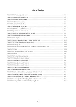
List of Tables
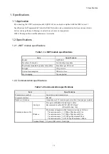
Table 1-1 J.NET module specifications .............................................................................................................. 1-1
Table 1-2 Communication specifications ........................................................................................................... 1-1
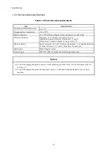
Table 1-3 Environmental specifications ............................................................................................................. 1-2
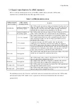
Table 1-4 JEMA standard services ..................................................................................................................... 1-3
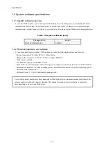
Table 1-5 System software (tool) ........................................................................................................................ 1-4
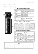
Table 2-1 Names and functions of parts ............................................................................................................. 2-1
Table 2-2 MODU No. and BIT RATE settings .................................................................................................. 2-1
Table 2-3 Signal names and descriptions ............................................................................................................ 2-1
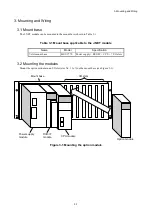
Table 3-1 Mount base applicable to the J.NET module ...................................................................................... 3-1
Table 3-2 Recommended cable specifications ..................................................................................................... 3-5
Table 4-1 Status display ...................................................................................................................................... 4-18
Table 4-2 Mounting state and setting state display in online mode .................................................................... 4-19
Table 4-3 NET status table addresses that can be set .......................................................................................... 4-21
Table 4-4 Station type list ................................................................................................................................... 4-25
Table 4-5 Station timeout calculation formula for different communication speeds .......................................... 4-25
Table 4-6 I/O types ............................................................................................................................................. 4-26
Table 4-7 List of transfer addresses that can be set ............................................................................................ 4-27
Table 5-1 I/O areas ............................................................................................................................................. 5-2
Table 5-2 NET status table configuration ........................................................................................................... 5-3
Table 5-3 S-table allocation (main module) ....................................................................................................... 5-5
Table 5-4 S-table allocation (sub module) .......................................................................................................... 5-5
Table 5-5 S-table allocation (sub2 module) ........................................................................................................ 5-6
Table 5-6 S-table allocation (sub3 module) ........................................................................................................ 5-6
Table 6-1 J.STATION communication time ........................................................................................................ 6-1
Table 7-1 Maintenance and inspection items ...................................................................................................... 7-1
Table 8-1 Details of Test and Maintenance diagnosis for J.NET modules ......................................................... 8-1
Table 8-2 Test item and module type selected by the setting switches ............................................................... 8-3
Table 8-3 LED states during the Test and Maintenance operation ..................................................................... 8-4
Table 8-4 Location of problem for lighting ERR LED, and corrective actions .................................................. 8-6
Table 8-5 Viewing detailed error information by using the tool ......................................................................... 8-7
Содержание 510VE
Страница 1: ...User s Manual Option J NET LQE540 E SEE 1 102 A ...
Страница 2: ...User s Manual Option J NET LQE540 E ...
Страница 15: ...S 12 Revision History Revision No History revision details Issue date Remarks A New edition Oct 2019 ...
Страница 27: ...This page is intentionally left blank ...
Страница 35: ...This page is intentionally left blank ...
Страница 73: ...This page is intentionally left blank ...
Страница 83: ...This page is intentionally left blank ...
Страница 91: ...This page is intentionally left blank ...


